Table of Contents
Advertisement
Quick Links
Advertisement
Table of Contents

Related Manuals for 2N IP Vario


Summary of Contents for 2N IP Vario
- Page 1 Installation manual 2N® IP Vario v.2.16 www.2n.com...
-
Page 2: Table Of Contents
Installation manual 2N® IP Vario Content: • 1. Product Overview • 1.1 Components and Associated Products • 1.2 Terms and Symbols • 2. Description and Installation • 2.1 Before You Start • 2.2 Mechanical Installation • 2.3 Electric Installation • 2.3.1 Overvoltage Protection •... -
Page 3: Product Overview
IP Vario can also be provided with RFID card reader modules. ® IP Vario is very easy to install. All you have to do is connect the system into your LAN via a network cable and feed it from a 12 V power supply or your PoE supporting LAN. -
Page 4: Components And Associated Products
Installation manual 2N® IP Vario • Up to 1999 telephone directory positions • Up to 20 user time profiles • Video codecs (H.263, H.263+, H.264, MPEG-4, JPEG) • Audio codecs (G.711, G.729, G.722, L16/16 kHz) • HTTP server for configuration •... - Page 5 Installation manual 2N® IP Vario • 3 buttons • control of one electric lock 2N Part No. • possibility of connecting card reader, extenders or 9137131(C)U information panel or additional switch Axis Part No. • available option with camera (C) 01307-001, 01314-001 5 / ...
- Page 6 Installation manual 2N® IP Vario • 6 buttons • control of one electric lock 2N Part No. • possibility of connecting card reader, extenders or 9137161(C)U information panel or additional switch Axis Part No. • available option with camera (C) 01308-001, 01315-001 6 / ...
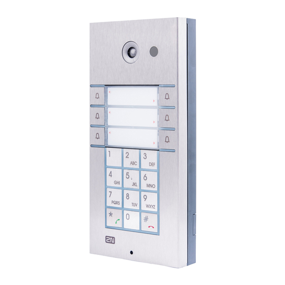
- Page 7 Installation manual 2N® IP Vario • 1 button • keypad 2N Part No. • control of one electric lock 9137111(C)KU • possibility of connecting card reader, extenders or Axis Part No. information panel or additional switch 01309-001, 01316-001 • available option with camera (C) •...
- Page 8 Installation manual 2N® IP Vario • 6 buttons • keypad 2N Part No. • control of one electric lock 9137161(C)KU • possibility of connecting card reader, extenders or Axis Part No. information panel or additional switch 01311-001, 01318-001 • available option with camera (C) •...
- Page 9 Installation manual 2N® IP Vario Extending Modules • Extending module • 8 buttons 2N Part No. • Dimension of the module 100 x 210 x 29 mm 9135181E Axis Part No. 01320-001 • Extending module • 16 buttons 2N Part No.
- Page 10 Installation manual 2N® IP Vario • Info panel • Backlit panel without buttons; used for insertion of a telephone 2N Part No. directory, company logo, house number, etc. 9135310E Axis Part No. 01322-001 Extenders • Spare button name plate 2N Part No. 9135301E Axis Part No.
- Page 11 Installation manual 2N® IP Vario • Info panel – name plate • Replacing cover for four name tags. 2N Part No. 9135311E • Helps you use a half of the extending module for insertion of a Axis Part No. telephone directory, working hours, etc.
- Page 12 Installation manual 2N® IP Vario Mounting Accessories • Surface 1-module roof • Dimensions: (103 x 218 x 60) mm (W x H x D) 2N Part No. 9135331E Axis Part No. 01323-001 • Wall mounting boxwith 1-module frame • Dimensions: (125 x 235 x 46) mm (W x H x D) 2N Part No. 9135351E...
- Page 13 Installation manual 2N® IP Vario • Wall mounting boxwith 1-module roof • Roof dimensions: (129 x 240 x 41) mm (W x H 2N Part No. 9135361E x D) Axis Part No. 01327-001 • Wall hole: (110 x 220 x 50) ±5 mm •...
- Page 14 The box with frame (without ® roof) allows for installation of 2N IP Vario in indoor applications so that the unit does not practically stick out (up to 1 mm). 14 / 113...
- Page 15 The elegant internal touch panel, 2N Indoor Touch 2N Part No. 91378375 2.0, is suitable for all 2N IP intercoms. On the panel’s Axis Part No. 01668-001 display not only can you find out who is at the door, but also start a conversation with the visitor, open the 2N Part No.
- Page 16 The elegant internal touch panel, 2N Indoor Touch Part Numbers: 2.0, is suitable for all 2N IP intercoms. On the panel’s 2N part No. 91378375WH display not only can you find out who is at the door, but also start a conversation with the visitor, open the Axis Part No.
- Page 17 Installation manual 2N® IP Vario ® • IP Handset • answering unit 2N Part No. Axis Part No. • white color 1120101W 02518-001 ® • IP Handset • answering unit 2N Part No. Axis Part No. • black color 1120101B 02519-001 ...
- Page 18 Installation manual 2N® IP Vario IP Phones • Yealink SIP T58A IP video phone • simple operation 2N Part No. 91378360 • HD quality video calls Axis Part No. 01586-001 • A display-equipped extender EXP50 (Part No. 91378363) can be added to the phone delivery to make up to 60 speed dialings.
- Page 19 Installation manual 2N® IP Vario Electric Locks Part No. 11202101 • Mini electronic doorstrike series 5 • electric opener designed for door frame installation • intended for such narrow profiles as aluminum, wood or PVC in particular • short sheet metal front cover version (130 mm) •...
- Page 20 Installation manual 2N® IP Vario Part No. 11202102-L • Mini electronic doorstrike series 5 – with momentum pin, long • electric opener designed for door frame installation • intended for such narrow profiles as aluminum, wood or PVC in particular •...
- Page 21 Installation manual 2N® IP Vario Part No. 11202104 • Mini electronic doorstrike series 5 – door signaling • electric opener designed for door frame installation • intended for such narrow profiles as aluminum, wood or PVC in particular • including a door state monitoring micro switch: open/closed •...
- Page 22 Installation manual 2N® IP Vario Part No. 11202105-L • Mini electronic doorstrike series 5 – fail-safe, long • electric opener designed for door frame installation • intended for such narrow profiles as aluminum, wood or PVC in particular • under voltage: opener secured, blocked •...
- Page 23 Electromechanical lock SAM 7255 • 72/55 self-locking lock with panic function • A key is necessary for door opening from the outside (or an electric pulse from a connected 2N IP intercom / reader). • convenient solution for emergency exits Part No.
- Page 24 • 92/35 self-locking lock with panic function • A key is necessary for door opening from the outside (or an electric pulse from a connected 2N IP intercom / reader). • convenient solution for emergency exits Part No. 11202301 •...
- Page 25 Installation manual 2N® IP Vario Part No. 11202303 • Cable protector FX300G • Provides secure passage and protection of the supply cable between the door frame and the door leaf. • 440 mm length Part No. 11202304 • Cable protector FX500G •...
- Page 26 Installation manual 2N® IP Vario Part No. 11202501 • Magnetic handle P300RP • fully replaces a mortise lock and handle • under voltage: door cannot be opened • at voltage interruption: magnets get disconnected, door opens • suitable for wooden, metal and glass doors Part No.
- Page 27 Installation manual 2N® IP Vario • FAQ: Electric locks – Difference between locks in 2N IP intercoms accesories Power Supply • PoE injetor – with EU cable • PoE injector – with US cable Part Numbers: • For power supply of intercom via ethernet cable 2N Part No.
- Page 28 Internal RFID card reader for installation in the basic 2N Part No. 9137430E ® module of the 2N IP Vario intercom. Allows the use of Axis Part No. 01333-001 EM4100 and EM4102 cards. Another two switches, two logical inputs and a Wiegand interface are available. It ®...
- Page 29 Installation manual 2N® IP Vario • Water-proof metal button • (suitable for Internal RFID card reader) 2N Part No. 9154004 Axis Part No. 01479-001 29 / 113...
- Page 30 2N Part No. 9159011 isolation of two devices separately power supplied Axis Part No. 01387-001 ® and interconnected via the Wiegand bus. The 2N Wiegand Isolator protects the interconnected devices against communication errors and/or damage. • External IP Relay – 1 output •...
- Page 31 External IP Relay – 4 outputs, PoE • Standalone IP device which can be controlled 2N Part No. 9137411E by HTTP commands sent by 2N IP intercom, which can thus control devices on unlimited distance. Axis Part No. 01398-001 • RFID card, type EM4100, 125 kHz 2N Part No. 9134165E...
- Page 32 Installation manual 2N® IP Vario • Exit button • (suitable for Internal RFID card reader or Security Part No. 9159013 relay) • A button for connection to a logic input for opening a door inside a building. • Magnetic door contact •...
- Page 33 Installation manual 2N® IP Vario • External 125 kHz RFID card reader • Secondary reader for connection to an internal reader. 2N Part No. 9159030 Allows control of card entry from both sides of the Axis Part No. 01389-001 door. IP67 cover, also suitable for exteriors. Reads EM4100 and EM4102 cards.
- Page 34 Installation manual 2N® IP Vario • USB RFID card reader 125 kHz • External RFID card reader for connection to a PC using 2N Part No. 9137420E a USB interface. Suitable for system management and Axis Part No. 01399-001 the addition of EM41xx cards via the PC application, ® ...
- Page 35 ® web interface or the 2N Access Commander application. It reads the same types of cards and devices as card readers in 2N IP intercoms. • 13.56 MHz/ISO/IEC 14443A Mifare Classic 1k & 4k, DESFire EV1, Mini, Plus S&X, Ultralight, Ultralight C •...
- Page 36 Installation manual 2N® IP Vario ® • Power supply for 2N Induction Loop • External power supply for the induction loop. 2N Part No. 9159052 • Input 230 V AC Axis Part No. 01393-001 • Output 12 V DC • AXIS A9188 Network I/O relay module •...
- Page 37 Installation manual 2N® IP Vario • Enhanced Integration 2N Part No. 9137907 • Enhanced Security 2N Part No. 9137908 • Gold 2N Part No. 9137909 • InformaCast 2N Part No. 9137910 Axis Part No. 01381-001 • 2N Part No. 9137915 •...
-
Page 38: Terms And Symbols
Installation manual 2N® IP Vario • Refer to the Configuration Manual for 2N IP intercoms, Subs. 3.2 Function Licensing for details. • For more accessories and particular advice please contact your local distributor of 2N products. 1.2 Terms and Symbols The following symbols and pictograms are used in the manual: ... -
Page 39: Description And Installation
• 2.5 Extending Module Connection 2.1 Before You Start Product Completeness Check Before you start please check whether the contents of the package of your new ® IP Vario complies with the following list. ® • 1x 2N IP Vario • 1x spare seal •... - Page 40 Installation manual 2N® IP Vario Installation type Symbol What you need for installation Indoor, flush mounting ® • IP Vario • Box with 1-module frame 9135351E or Box with 2-module frame 9135352E Outdoor, on surface ® • IP Vario • Surface 1-module roof 9135331E or Surface 2-module roof 9135332E ®...
- Page 41 Installation manual 2N® IP Vario Installation type Symbol What you need for installation Outdoor application • Environments where the product is means exposed to rain or where water may flow down the walls (fence, outer wall of a building, e.g.).
- Page 42 Installation manual 2N® IP Vario Caution • Before starting the mechanical installation on a selected place, make sure carefully that the preparations connected with it (drilling, wall cutting) cannot damage the electrical, gas, water and other existing wires and pipes.
- Page 43 ® 2. Use the hexagon key wrench included in the supply and remove the 2N IP Vario metal cover. Remove the screw in the lower part of the metal cover and fold out the cover.
- Page 44 ® 7. Fix 2N IP Vario on the wall with screws. Carry the supply cables (Ethernet, lock, power cables) to the basic module box through one of the holes. Seal the screw hole carefully with some cement or non-aggressive silicone to avoid water infiltration.
- Page 45 Make sure that the cables are not squeezed while installing the plastic cover. For the correct cable installation. ® 10.Remove the protective foil from the display (for display-equipped 2N IP Vario versions only). 11. Make sure that the cables are placed properly inside and that none of them obstructs a perfect cover closure.
- Page 46 Installation manual 2N® IP Vario Warning • Remember to tighten all the four corner screws to fix the loudspeaker seal after electric installation to avoid water in-leak! A PZ1 cross-head screwdriver is recommended. 14. Take out the name plates from the plastic cover. Use a flat-bladed screwdriver, for example.
- Page 47 Installation manual 2N® IP Vario 19. Check whether a silicone seal is inserted in the top groove of the plastic cover. A spare seal package is included. 20. Close the metal cover and fix it with screws. 47 / 113...
-
Page 48: Electric Installation
Name Tag Material and Printing ® Each 2N IP Vario package includes a sheet of transparent foil for laser printing. Cut the printed foil into pieces and insert the labels in the name plates. Do not use paper to avoid water in-leak and paper damage. - Page 49 The device must be part of the electrical system of the building. ® IP Vario is fed through the PoE (Power over Ethernet) technology. No additional cabling is therefore necessary. If your Ethernet is not equipped with the PoE technology, it is possible to use a PoE injector, Part No. 91378100.
- Page 50 ® configuring 2N IP Vario are indicated on the board. The UTP cable for the Ethernet connection is to be connected to the terminal block X2 as shown in table below. The terminal block can be removed from the PCB. The connection of each of the connectors is described in the subsections below.
- Page 51 Installation manual 2N® IP Vario Description of Connectors, PCB Versions 535v1, 535v2 51 / 113...
- Page 52 Installation manual 2N® IP Vario Description of Connectors, PCB Versions 535v5 52 / 113...
- Page 53 Installation manual 2N® IP Vario Description of Connectors, PCB Versions 535v8 53 / 113...
- Page 54 Terminal block X2 includes 10 terminals whose functions are distinguished by colour. Terminals ® 5–10 are used for connecting 2N IP Vario to the Ethernet. Terminals 3–4 are designed for connecting the electric lock and terminals 1–2 help connect an external 12 V / 2 A DC power supply if no PoE power supply is available.
- Page 55 The terminal block is included in the package. To adjust an already installed ® IP Vario, disconnect it IP from the power supply. Then pull to remove the terminal block from the printed circuit board. Insert the wires under the respective terminals.
- Page 56 The electric lock can be connected to terminals 3 and 4 of terminal block X2. Terminal Block Connection for Electric Lock ® Terminals 3 and 4 are connected to a relay on the 2N IP Vario board. The relay terminals may act as normally open or normally closed contacts. Configuration is performed through the configuration connector X1 as described in the Configuration Connector Connection subsection.
- Page 57 IP Vario. ® Using a PoE injector, Part No. 91378100. 2N IP Vario is then powered through an Ethernet cable as shown in Tab. 1 above. Using a power adapter, Part No. 91341481E. The external power supply from a power adapter can be connected to terminals 1 and 2.
- Page 58 Connection of Configuration Connector Jumpers Display Connector ® The display connector includes the name plate backlighting ON/OFF switching pins and 2N IP Vario resetting pins. The remaining pins are intended for display connection. 58 / 113...
- Page 59 F_RES position in the display-equipped models with 535v1 and 535v2 board versions). ® Switch 2N IP Vario on and wait for the acoustic start signal. ® Switch 2N IP Vario off. Remove the jumper from the resetting (default setting) position (put the display switch into the NORMAL position in the display-equipped models with 535v1 and 535v2 board versions).
- Page 60 ® To reset the default values of a display-equipped 2N IP Vario, put the switch in the display right-hand bottom corner in position F_RES. This applies to modules with board versions 535v1 and 535v2 only. For 535v5 versions, use a jumper at connector X13.
- Page 61 Note • The delay after pressing RESET till the first light and sound signalling is set to 15– 35 s depending on the 2N IP intercom/answering unit model used. ® • 24 s is the valid value for 2N IP Vario HW version 8.
- Page 62 Installation manual 2N® IP Vario Dynamic IP Address Setting Follow the instructions below to switch on the Dynamic IP address mode (DCHP ON): • Press and hold the RESET button. • Wait until the red and green LEDs go on simultaneously on the device and the acoustic signal ...
- Page 63 Installation manual 2N® IP Vario • Wait until the red and green LEDs go on simultaneously and the acoustic signal can be heard (approx. 15–35 s). • Wait until the red LED goes off and the acoustic signal can be heard (approx. for another 3 s).
- Page 64 IP Vario software version. Caution ® • The 2N IP Vario modules ending with U (i.e. 91371…U) can only be equipped with the card reader. Card Reader Mounting ® Power off 2N IP Vario. Use a hexagonal wrench to unscrew and remove the metal cover.
- Page 65 Installation manual 2N® IP Vario Replace and fix the plastic cover using cross-head screws. Replace and screw back the metal cover. Grounding We recommend you to ground the intercom in order to improve the static electricity resistance. All you need for a proper grounding is a cable of the minimum cross-section of 4 mm and a...
- Page 66 Installation manual 2N® IP Vario Insert the crimped cable at the marked point. Assemble the set and ground the cable. 66 / 113...
- Page 67 Installation manual 2N® IP Vario Available Switches Location Name Description Basic Unit Relay 1 Passive switch: NO and NC contacts, up to 30 V / 1 A AC/DC. Used for connection of non-critical devices only (lights, e.g.). Active switch output: 10 up to 12 V DC depending on power supply (PoE:...
-
Page 68: Overvoltage Protection
2N device wiring may be exposed to atmospheric effects resulting in overvoltage that may subsequently damage any devices installed outside the building, on its outer wall or roof. -
Page 69: Completion
Mounting the metal sheet cover follow the steps included in the subsection dedicated to name plate removal. Make sure that the cover fits well and is perfectly flat. If its bottom ® part is loose, the mounting wall is probably uneven. Support the corners to avoid 2N IP Vario bending. - Page 70 Installation manual 2N® IP Vario Most Frequent Mounting Errors For illustration, a part of the plastic cover is removed in the figures below to reveal the sealed loudspeaker and the cover-seal touch point. The cross section plane is marked white for better orientation.
-
Page 71: Extending Module Connection
Installation manual 2N® IP Vario 2.5 Extending Module Connection ® IP Vario allows to connect following extending modules: • Extending button modules 71 / 113... - Page 72 Extending button modules ® IP Vario features an easy installation of extending button modules. Extending modules are connected using a single cable (included in every extender delivery) in a chain pattern (every additional unit is connected with the previous one). Each extending module has two connectors ®...
- Page 73 Installation manual 2N® IP Vario Maximum Count of Extenders 9135181E (1× 8 buttons) 9135182E (2× 8 buttons) The table above shows how to combine modules with single (whole) and double buttons. Module Cable Interconnection • The cable is included in every extending module delivery. Both its ends are the same.
- Page 74 Installation manual 2N® IP Vario Caution • The extending modules must be connected mutually and with the basic unit by means of a formed piece supplied with the extending module!!! Button Numbering Button numbering – one-button with a whole-button set Button numbering –...
- Page 75 Installation manual 2N® IP Vario Button numbering – double-button set Caution • For the time being, AntiVandal panels are available only for single-button sets with one extending module at most. Button Numbering – Info Panel Sets Installing the info panel name plate, Part No. 9135311E, into any of the extending modules will not change the numbering system (the buttons on the info panel sides will remain functional).
- Page 76 Additional Switch is suitable for e.g. electric door lock or low voltage logical inputs of e.g. gate and barrier control systems. Function: ® The 2N IP Vario Additional Switch adds one additional switch to the ® IP Vario basic unit. Specifications: • Passive switch: NO and NC contacts, up to 30 V / 1 A AC/DC ...
- Page 77 Installation manual 2N® IP Vario Module mounting: Switch off the intercom before module installation. Module settings: Refer to the Configuration manual for 2N IP intercoms for details. Connection: Switch Connection Normally opened NO – C Normally closed NC – C 77 / 113...
- Page 78 Installation manual 2N® IP Vario Internal RFID Card Reader 125 kHz The Internal RFID Card Reader (Part No. 9137430 E) is used for reading RFID card Ids in the 125 ® kHz band. This module is intended for mounting into the 2N IP Vario model 91371..U. Function: ®...
- Page 79 IP Vario basic unit bottom connector making sure that the microphone cable lies under the module. ® • Use the enclosed screws to fix the reader module to the 2N IP Vario plastic base. • Connect the wires for the reader module interface(s) if necessary.
- Page 80 The 2N Security Relay is a device installed between an intercom (outside the secured area) ® and the electric lock (inside the secured area). The 2N Security Relay includes a relay that can only be activated if the valid opening code is received from the intercom.
- Page 81 Installation manual 2N® IP Vario Specifications: Passive switch: NO and NC contacts, up to 30 V / 1 A AC/DC Switched output: • Where the security relay is fed from the intercom, 9 to 13 V DC is available on the output depending on the power supply (PoE: 9 V;...
- Page 82 Error – wrong code received Configuration: ® • Connect the 2N Security Relay to the properly set intercom switch output; refer to the Configuration manual for 2N IP intercoms. Make sure that one LED at least on ® the 2N Security Relay is on or blinking. ® •...
- Page 83 Installation manual 2N® IP Vario ® • FAQ: Security Relay – what it is and how to use it with 2N IP intercom? Connection: Video Tutorial: Security Relay Installation and Configuration Sorry, the widget is not supported in this export.
- Page 84 Installation manual 2N® IP Vario Wiegand Isolator ® The 2N Wiegand Isolator (Part No. 9159011) is usef for galvanic isolation of the Wiegand bus. ® The 2N Wiegand Isolator is designed for galvanic isolation of two devices with separate power supply and interconnected via the Wiegand bus.
- Page 85 Installation manual 2N® IP Vario Connection: 85 / 113...
- Page 86 Installation manual 2N® IP Vario Wiegand Input Technical Parameters Current 5 mA Input resistance 680 Ohm Pulse length 50 μs Delay between pulses approx. 2 ms Recommended Wiring Diagram for Reader with Bus Driver Recommended Wiring Diagram for Reader with Open Collector (OC) Output...
- Page 87 You can place the mated A and B connectors into the 2N IP intercom cover. The connectors help you connect stripped cables. Open the connector by pushing a thin screwdriver onto the white spots at its front and close the connector by sliding the movable part through a side gap.
- Page 88 Installation manual 2N® IP Vario Specifications: • Supply voltage: 8–18 V DC • Supply current at 12 V supply: • 1 Ω load, full power output; 1.4 A, sine wave signal; 1 A, pink noise signal • 8 Ω load, half power output; 550 mA, sine wave signal; 400 mA, pink noise signal •...
-
Page 89: Function And Use
You have to know the IP address of your device to log in to the integrated web server. By ® default, 2N IP Vario is switched into the dynamic IP address mode, i.e. it obtains the IP address automatically if a properly set DHCP server is available in your LAN. If no such DHCP server is ®... - Page 90 6-buttons models: Press the fifth quick dial button on the basic unit five times. ® • IP Vario will read its IP address. • If the address is 0.0.0.0, it means that the intercom has not obtained the IP address from the DHCP server.
- Page 91 Static IP Address Setting Follow the instructions below to enable the static IP address mode: ® • Connect 2N IP Vario to the power supply (or, disconnect and reconnect it if already connected). • Wait for the first acoustic signal • Press following buttons sequentially: •...
- Page 92 The 2, 1, 1, 2, 2, 3 sequence must be entered within 30 seconds after the first sound signal for security reasons. The inter-digit delay may be 2 s at most. ® IP Vario gets the IP address upon restart only if the DHCP server is configured properly. Mode Switching with 1-Button Models ®...
-
Page 93: Intercom Control As Viewed By External User
Installation manual 2N® IP Vario • Network parameter reset and DHCP switch are signaled by the sound. • For devices with FW versions 2.33 and lower, wait until the device is automatically restarted. • After restart, the static IP address mode is switched into the dynamic IP address and vice versa. - Page 94 ® The 2N IP Vario telephone directory may contain up to 1999 pre-programmed positions. You can use the quick dialling buttons for positions 1 to 54 only. To retrieve the remaining positions, use the numeric keypad if Dial Users by Phonebook Position is enabled; refer to the Intercom Configuration / Hardware / Keypad subsection of Configuration Manual.
- Page 95 to reject the call. Code Door Opening (Switch Activation) ® IP Vario is equipped with a door unlocking switch. To activate the switch enter the valid code (refer to the Intercom Configuration / Hardware / Switches subsection of Configuration Manual) on the numeric keypad.
-
Page 96: Display-Equipped Intercom As Viewed By External User
3.3 Display-Equipped Intercom as Viewed by External User ® Until the display program is uploaded to 2N IP Vario, the display shows the 2N logo; refer to the ® figure below. In this state, 2N IP Vario behaves and is controlled like no-display models, see ®... - Page 97 You can also enter the door lock opening codes and activate or deactivate a user or profile in this ® mode. For steps refer to the no-display 2N IP Vario subsection. Push the quick dialling button 6 to move to the Telephone directory mode and the button to move to the Calling to number mode (only if the telephone function is enabled, see Miscellaneous). ...
- Page 98 Installation manual 2N® IP Vario Calling to Number ® If the Telephone function enable is selected (see Miscellaneous), 2N IP Vario can be used for calling to selected telephone numbers in a standard way. Push in the Electronic name tag mode to move to this mode. Push the quick dialling button 3 or the ...
- Page 99 Installation manual 2N® IP Vario Phone Book A structured phone book as defined by the display program is displayed in the telephone directory mode. To browse through the telephone directory use the numeric keypad arrow keys (i.e. keys 2, 4, 6 and 8). Use the up and down arrows to move between the items. Push the right arrow to establish a call or move to a subgroup.
- Page 100 To browse through the contacts found and select the required one, push the quick dialling button 6, thus recovering the arrow function of the numeric keypad. Status Information ® In addition to the above described modes, the 2N IP Vario display indicates various device statuses: Call being set up Ringing –...
-
Page 101: Intercom Control As Viewed By Internal User
Calling to 2N IP Vario ® IP Vario allows to answer an incoming call too. To set the required parameters use the Incoming calls item, refer to the Intercom Configuration / Services / Phone / Calls subsection of Configuration Manual. Code Door Opening (Switch Activation) ®... -
Page 102: Maintenance
Installation manual 2N® IP Vario Profile Activation and Deactivation You can activate or deactivate a profile and define call routing to the telephone numbers assigned to the profile using the numeric keypad. For more details refer to the Intercom Configuration / Directory / Time Profiles subsection of Configuration Manual. -
Page 103: Downloads
The manufacturer reserves the right to modify the product in order to improve its qualities. ® • IP Vario contains no environmentally harmful components. When the product's service life is exhausted and you would like to dispose of it please do so in accordance with applicable legal regulations. 3.6 Downloads... -
Page 104: Technical Parameters
Installation manual 2N® IP Vario 4. Technical Parameters Signalling protocol • SIP (UDP, TCP, TLS) Buttons • Button design: stainless-steel push buttons • Count of buttons: 1, 3 or 6 • Button extension: up to 54 buttons • Numerical keypad: optional Audio • Volume control: adjustable •... - Page 105 Installation manual 2N® IP Vario Video stream • Protocols: RTP / RTSP / HTTP • Codecs: H.263, H.263+, H.264, MPEG-4, M-JPEG • IP camera function: Yes, ONVIF v2.4 profile S compatible Bandwidth • Audio codecs • PCMA, PCMU – 64 kbps (with 85.6 kbps headers) •...
- Page 106 Installation manual 2N® IP Vario • Video codecs Set the video codec data flows in the Services / Phone / Video menu for calls and in the Services / Streaming / RTSP menu for streaming. The set bandwidth represents the value that the codec has to approach on a long-time average.
-
Page 107: General Drawings
Installation manual 2N® IP Vario Mechanical properties • Working temperature: −20 °C to 55 °C • Working relative humidity: 10 % – 95 % (non-condensing) • Storing temperature:−40 °C to 70 °C • Dimensions: (210 x 100 x 29) mm • Weight: 500 g •... - Page 108 Installation manual 2N® IP Vario Flush mounting 108 / 113...
-
Page 109: Supplementary Information
5.1 Troubleshooting For the most frequently asked questions refer to faq.2n.cz. 5.2 Directives, Laws and Regulations ® IP Vario conforms to the following directives and regulations: • 2014/53/EU for radio equipment • 2011/65/EU on the restriction of the use of certain hazardous substances in electrical and electronic equipment •... - Page 110 DDA compliance: 2N TELEKOMUNIKACE intercoms comply with the Disability Discrimination Act 2005 (DDA) under the following conditions: The intercoms are mounted so that their lower edge is between 100 and 120 centimeters above the floor.
-
Page 111: Other Countries Legislation
Installation manual 2N® IP Vario 5.3 Other Countries Legislation Thailand 5.4 General Instructions and Cautions Please read this User Manual carefully before using the product. Follow all instructions and recommendations included herein. Any use of the product that is in contradiction with the instructions provided herein may result in malfunction, damage or destruction of the product. - Page 112 Installation manual 2N® IP Vario The manufacturer assumes no responsibility for any malfunction, damage or destruction of the product caused by incompetent replacement of parts or due to the use of reproduction parts or components. The manufacturer shall not be liable and responsible for any loss or damage incurred as a result of a natural disaster or any other unfavourable natural condition.
- Page 113 Installation manual 2N® IP Vario 113 / 113...
Need help?
Do you have a question about the IP Vario and is the answer not in the manual?
Questions and answers