Table of Contents
Advertisement
Advertisement
Chapters
Table of Contents

Related Manuals for 2N Analog Vario


Summary of Contents for 2N Analog Vario
- Page 1 Installation manual 2N® Analog Vario v.1.6 www.2n.com...
-
Page 2: Table Of Contents
Installation manual 2N® Analog Vario Content: • 1. Product Overview • 1.1 Components and Associated Products • 1.2 Terms and Symbols Used • 2. Description and Installation • 2.1 Before You Start • 2.2 Mechanical Installation • 2.3 Electrical Installation •... -
Page 3: Product Overview
® Analog Vario also has a switch that controls the electric lock by using any telephones keypad (by tone-dialling the password). In addition to the buttons, you can use a numerical keypad, which is used as a code lock. Using the keypad, you can operate the device as a button telephone and dial the required numbers directly or retrieve them from any of the 54 memories available. -
Page 4: Components And Associated Products
Installation manual 2N® Analog Vario • Applicable as a standard telephone and code lock (keypad version) Advantages of Use • Flat design – installation no need to cut into mounting surface • Hermetically sealed, solid state buttons • Electronics is separated from name plates •... - Page 5 Installation manual 2N® Analog Vario • Main unit • 3 buttons Part No. 9135130E 5 / 77...
- Page 6 Installation manual 2N® Analog Vario • Main unit • 3 × 2 buttons Part No. 9135160E • Main unit • 1 button + keypad Part No. 9135110KE 6 / 77...
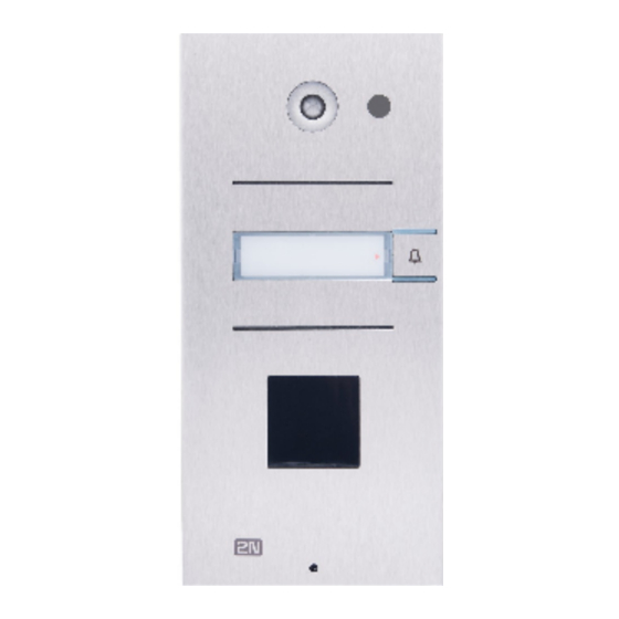
- Page 7 Installation manual 2N® Analog Vario • Main unit • 3 buttons + keypad Part No. 9135130KE • Main unit • 3 × 2 buttons + keypad Part No. 9135160KE 7 / 77...
- Page 8 Installation manual 2N® Analog Vario • Info panel • backlit button-less panel Part No. 9135310E • used for the telephone directory, house number, etc. • Extender unit • 8 buttons Part No. 9135181E 8 / 77...
- Page 9 Installation manual 2N® Analog Vario • Extender unit • 8 × 2 buttons Part No. 913582E • Info panel – name plate • Replaces four name plates with one cover. Part No. 9135311E • Enables the use of one half of the extender unit for the telephone directory, opening hours, etc.
- Page 10 Installation manual 2N® Analog Vario All the above-mentioned units can be wall mounted without requiring any additional accessories. All the main units can be complemented with a camera, proximity reader (see later) and display (under preparation). Additional accessories (see later) are needed for outdoor flush mounting purposes.
- Page 11 Installation manual 2N® Analog Vario • Wall mounting box with 1-module roof • Roof dimensions: (129 × 240 × 41) mm (W × H × Part No. 9135361E • Wall hole: (110 × 220 × 50) ±5 mm 11 / 77...
- Page 12 The box with ® frame (without roof) allows for installation of 2N Analog Vario in indoor applications so that the unit does not practically stick out (up to 1 mm).
- Page 13 Installation manual 2N® Analog Vario GSM and VOIP Connection Accessories ® EasyGate PRO - GSM gateway Part No. 501333E Video Accessories • In-built colour CCD camera • PAL, resolution 420 TV rows, sensitivity 2 lux. Part No. 9135200E • Camera can be built in any basic unit. In the case of poor light, the camera switches into the monochrome mode automatically.
- Page 14 Installation manual 2N® Analog Vario • BEFO 1211MB with mechanical blocking Part No. 932090E Other Accessories • Additional switch (9135250E) • Switching and breaking contact option Part No. 9135250E • time-unlimited switching Part No. 9135251E • up to 48 V / 2 A •...
-
Page 15: Terms And Symbols Used
Line hang-up/clear – call end, handset hang-up. • DTMF – dual tone multi-frequency signalling. • PSTN – public switched telephone network. ® • Outgoing call – 2N Analog Vario-telephone connection made, e.g. by a pressing a button. ® • Incoming call – telephone-2N Analog Vario connection. ® •... - Page 16 Installation manual 2N® Analog Vario Manual Symbols The following symbols and pictograms are used in the manual: Safety • Always abide by this information to prevent persons from injury. Warning • Always abide by this information to prevent damage to the device.
-
Page 17: Description And Installation
Installation manual 2N® Analog Vario 2. Description and Installation ® This section describes the 2N Analog Vario product and its installation. Here is what you can find in this section: • 2.1 Before You Start • 2.2 Mechanical Installation • 2.3 Electrical Installation •... - Page 18 Analog Vario Surface 1-module roof 9135331E or Surface 2-module roof 9135332E ® Outdoor, flush mounting Analog Vario Wall mounting box with 1- module roof 9135361E or Wall mounting box with 2-module roof 9135362E Indoor application means Indoor areas with a low relative air humidity (e.g., hallways, offices and other heated...
- Page 19 Surface Mounting ® Drill holes according to the template included in the 2N Analog Vario supply. Insert the included dowels in the wall holes. 19 / 77...
- Page 20 Installation manual 2N® Analog Vario ® Use the hexagon key wrench included in the supply and remove the 2N Analog Vario metal cover. Remove the screw in the lower part of the metal cover and fold out the cover. Use a cross-head screwdriver to remove the plastic cover and demount the cover.
- Page 21 ® Fix 2N Analog Vario on the wall with screws. Carry the supply cables (Ethernet, lock, power cables) to the basic module box through one of the holes. Seal the screw hole carefully with some cement or non-aggressive silicone to avoid water infiltration.
- Page 22 For the correct cable installation. ® Remove the protective foil from the display (for display-equipped 2N Analog Vario versions only). Make sure that the cables are placed properly inside and that none of them obstructs a perfect cover closure.
- Page 23 Installation manual 2N® Analog Vario Remove the inserts from the name plates. Insert the printed foil labels. Put the inserts back in the name plates. Replace the name plates, clicking them into position. The name plates hold the matt foil inserted underneath.
-
Page 24: Electrical Installation
Name Tag Material and Printing ® Each 2N Analog Vario package includes a sheet of transparent foil for laser printing. Cut the printed foil into pieces and insert the labels in the name plates. Do not use paper to avoid water in-leak and paper damage. - Page 25 Installation manual 2N® Analog Vario Display connector (for version 10 only) Voice memory One-chip Hands-Free telephone Switch 2 connector Keypad backlight connector Connector for non-standard functions Microphone connector Keypad connector Extension unit connector Serial number Main microprocessor Configuration jumper block...
- Page 26 Installation manual 2N® Analog Vario • LIGHT – These two terminals are connected to the 12V power supply with arbitrary polarity. The power supply can feed the electric lock too. • LINE – These two terminals are connected to the analogue telephone line with any polarity.
- Page 27 ® case recommended to connect 2N Analog Vario in parallel to another telephone or ® another 2N Analog Vario door communicator. It is neither admissible to use equipment that switches one line between two or more sets (intelligent double branch, etc.). 27 / 77...
- Page 28 Typical Electric Lock Connection ® Analog Vario contains a solid-state switch equipped with V-MOS transistors, which is able to switch both ac and dc regardless of polarity. Make sure that the current and voltage values do not exceed limits (refer to the Technical Data) and that the technical parameters of the lock and power supply are compatible.
- Page 29 The above mentioned currents are maximum values at 12V. Cable Arrangement inside the Cover ® We recommend you to use a UTP cable (8-wire, approx. 5.5 mm output diameter) for 2N Analog Vario connection. Push the cable into the groove on the left side of the cover. If you combine this cable with another one (e.g.
-
Page 30: Camera Installation
Connection of Switch 2 ® A new additional switch, Part No. 9135250E, has been designed for 2N Analog Vario. It can be mounted into any basic unit, as an added option. To connect it, follow the instructions included in the switch delivery. -
Page 31: Extending Module Connection
(Part No. 9134137, MPEG4 LAN video server). A coaxial or twisted cable can be used for connection. ® A sight glass is included in the delivery, which replaces the non-transparent 2N Analog Vario basic unit sight glass imitation. To install the camera, follow the instructions that come with it. - Page 32 Installation manual 2N® Analog Vario 8-Button Extender Module Connection to Basic Unit 16-Button Extender Module Connection to Basic Unit Caution • Extension modules must be interconnected by mounting jumper (tunnel), delivered together with each extension unit. This part is made from conductive plastic.
- Page 33 Installation manual 2N® Analog Vario Maximum Count of Extenders 9135181E (1×8 buttons) 9135182E (2×8 buttons) The table above shows how to combine modules with single (whole) and double buttons. 33 / 77...
-
Page 34: Buttons Labels - Insertion, Replacement
Connecting the info panel module, order No. 9135310E, will result in omission of eight numbers. 2.6 Buttons Labels - Insertion, Replacement Instructions ® Remove the 2N Analog Vario metal cover. To do this, use a hexagonal key, unscrew the screw as shown in the figure and take the cover off. 34 / 77... - Page 35 Installation manual 2N® Analog Vario Remove the name plates as shown in the figure using, e.g., a screw driver. Remove the name plate inserts as shown in the figure. Insert the labels printed on foil (see later). Replace the name plate inserts.
- Page 36 ® Every 2N Analog Vario delivery includes a sheet of transparent foil that can be easily printed, with a laser printer. Cut the printed foil into pieces and insert the labels into the name plates. Do not use paper to avoid water logging.
-
Page 37: Mounting - Completion
Mounting the metal cover follow the steps included in the subsection dedicated to name plate removal. Make sure that the cover fits well and is perfectly flat. If its bottom part is ® loose, the mounting wall is probably uneven. Support the corners to avoid 2N Analog Vario bending. - Page 38 Installation manual 2N® Analog Vario 38 / 77...
- Page 39 Installation manual 2N® Analog Vario 39 / 77...
-
Page 40: Function And Use
3.6 Downloads 3.1 Programming ® All 2N Analog Vario parameters, including the keypad ones, are set remotely using any tone- ® dialling telephone set (or a mobile phone). First call 2N Analog Vario and enter the programming mode. The access to this mode is service password protected. - Page 41 Switch Password Programming ® Each switch can be controlled with up to 10 different passwords that are listed in the 2N Analog Vario memory. Passwords can be added to the list using functions 811 and 821 and deleted with functions 812 and 822 individually. The default status is a single password in the list, namely 00 for switch 1 and 11 for switch 2.
- Page 42 The timeout is 5 seconds; every character is followed by ® 30 seconds for you to think over your setting. The 5-second limit starts when 2N Analog Vario has read all that relates to the current user position in the programming menu. The timeout can be prolonged –...
-
Page 43: Full Parameter Chart
Installation manual 2N® Analog Vario If You Forget the Service Password If you forget the service password, contact the manufacturer. The manufacturer can change your service password to 12345 remotely without altering any other parameter. 3.2 Full Parameter Chart Parameter... - Page 44 Installation manual 2N® Analog Vario Parameter Parameter Name Range Default Note (function) Enter up to 10 up to 16 • Passwords 00 and 11 switch 1 digits cannot be entered passwords from the keypad! • Up to 10 switch...
- Page 45 Installation manual 2N® Analog Vario Parameter Parameter Name Range Default Note (function) Automatic 0–4 0 = disabled 1 = loud with Multiple Number for all buttons confirmation Dialling type 2 = silent with confirmation 3 = SP without confirmation 1)
- Page 46 Installation manual 2N® Analog Vario Parameter Parameter Name Range Default Note (function) Microphone 0–3 0 = Maximum power-up level microphone sensitivity Automatic 0–3 3 = Maximum response response speed speed Reception volume 0–15 15 = Maximum reception volume Transmission 0–15...
- Page 47 Installation manual 2N® Analog Vario Parameter Parameter Name Range Default Note (function) Minimum busy 0–255 8 = 0.08s These parameters tone or pause control the busy tone duration detection. They are used for call termination and automatic dialling. Maximum busy 0–255...
- Page 48 Installation manual 2N® Analog Vario Parameter Parameter Name Range Default Note (function) Minimum ringing 1–200 50 = 0,5 s 2) The longest ringing tone time period pause must be in the interval between parameters 952 and 953. Minimum long 5–100...
- Page 49 Installation manual 2N® Analog Vario Parameter Parameter Name Range Default Note (function) Count of message 0–9 There is a 3-second repetitions pause between every two messages. Intercom 16 digits The number enables identification intercom identification. number Message options 2 digits...
- Page 50 Installation manual 2N® Analog Vario Parameter Parameter Name Range Default Note (function) language 0–8 selection for a 1 = English message 2–3 = 4 = German 5–7 = 8 = Portuguese 9 = Dutch10 ... 99 = silence Note: See Survey of messages in Subs.
-
Page 51: Language
• Terminology: For the purpose hereof, parameter means a value that is stored in ® the 2N Analog Vario memory and can be re-programmed. Function is a means of execution of another service such as initialisation, software version identification and so on. • 1) Types 3 and 4 of Automatic Dialling without Confirmation differ from each other in how they process very short calls (a few seconds). - Page 52 Installation manual 2N® Analog Vario Explanation of Some Parameters 824 - Second Switch Synchronisation Set the parameter to a non-zero value to make switch 2 activate automatically with a defined delay if switch 1 is activated. Useful where two doors are close to each other.
-
Page 53: Function Description
(Mr. Smith's in this case) telephone is ringing. If ® the 2N Analog Vario unit is connected to a telephone system you may be able to tag the port ® that 2N Analog Vario is connected to so that you can see on the ringing phone that it ® ... - Page 54 Door opening ® Analog Vario contains a switch to which an electric lock can be connected (not included in this pack). This switch can be telephone keypad controlled using a (digital) password in two ways as shown in the default password 00 example below: or ...
- Page 55 (see the Signals Overview). Call extension ® Analog Vario beeps 10 seconds before the call end to extend the call by 30 seconds press on your telephone (DTMF). You can use this function repeatedly. The visitor, however, cannot use this function! ...
- Page 56 Installation manual 2N® Analog Vario Caution ® • The above mentioned functions (except for calls to 2N Analog Vario) require a tone-dialling telephone set. Signals Overview Signal Name Meaning Confirmation Sent immediately after line seizure for incoming calls (can be heard by the calling party);...
- Page 57 Code Lock ® The electronic lock connected to 2N Analog Vario can not only be activated by the phone but also directly from the door using the keypad. In this mode, the keypad behaves like a standard code lock with the following features: •...
- Page 58 ® is made. You can use 2N Analog Vario as if it had up to 54 separate buttons, which saves buying the extender units and space on the installations wall. The ideal solution is to use a few standard buttons for the most important speed dialling options e.g. Warden, Reception and then provide a list of pre-programmed options via the optional info panel that can be purchased.
- Page 59 • Warning! Password 11 may not be used! • Traditional button telephone ® • gets 2N Analog Vario ready to dial a number. • Dials a number. • Transmits into tone dialling during pulse dialling. • Transmits a character in tone dialling. ...
- Page 60 ® • Can I use the code lock while another person is speaking through 2N Analog Vario? Yes but this is not advisable as you should be aware that the password is private and could contravene security.
- Page 61 Installation manual 2N® Analog Vario • Keyboard letters facilitate password remembering. For example, it is easier to remember a 9-letter word (e.g. crocodile) than a 9-digit number (276263453). • It is not recommended to use such passwords as 3333. This leads to a considerable wear and tear of one button and an unauthorised person may guess your password easily.
-
Page 62: Section For Advanced Users
3.4 Section for Advanced Users Automatic Multiple Number Dialling ® When you press a 2N Analog Vario button, you may find out that the called line is busy or the ® called party is absent. 2N Analog Vario is able to identify these situations and solve them by Automatic Multiple Number Dialling if one of three automatic dialling modes is enabled. - Page 63 This mode recognises the ringing tone and if the tone ends before the predefined count of ® rings, 2N Analog Vario regards this as a successful connection, this solution is not fully reliable because detection may be hindered by noise, etc. No message is played back in this mode. 63 / 77...
- Page 64 Installation manual 2N® Analog Vario Evaluation of Situations in Audible Automatic Dialling without Confirmation Situation ® Analog Vario Action Busy tone Hangs up in approximately 2 seconds and dials the next number. Call or silence without previous ringing Waits for the preset timeout (log-in time), then tone hangs up and dials the next number.
- Page 65 The DTMF is used as the most reliable criteria for successful connection. The called line must press on its telephone. If the called number is busy or remains ® unanswered until the preset timeout or in other cases (see the table), 2N Analog Vario dials the next number in the sequence. ...
- Page 66 PSTN connection. Excessive noise in the surroundings may also have a negative impact. However, this may only decelerate automatic dialling ® (the busy tone may not be recognised, e.g.). Even if 2N Analog Vario cannot identify the DTMF, the connection is established (yet for a shorter time).
- Page 67 If Automatic Multiple Number Dialling with Confirmation or Silent Automatic Multiple Number ® Dialling is enabled, 2N Analog Vario can be controlled as shown in the table below. For convenience, commands 1 to 5 are arranged as they are usually used. DTMF Character Function ® ...
-
Page 68: English
Installation manual 2N® Analog Vario Survey of Messages The table below includes a survey of language versions for standard announcements. English is selected by default. To select another language, use parameters 976 and 977. Value of Language End of call message... -
Page 69: German
Dutch ..... language. Arrival/Departure, Day/Night Modes ® Analog Vario can identify easily where to 'route' (switch) a call after a button is pressed. All ® you have to do is call 2N Analog Vario and enter the following: • I'm leaving: ... -
Page 70: Maintenance
3.5 Maintenance Cleaning ® If used frequently, 2N Analog Vario, especially the keypad, gets dirty. To clean it, use a piece of soft cloth moistened with clean water. We recommend you to obey the following principles while cleaning: • Never use aggressive detergents (such as abrasives or strong disinfectants);... -
Page 71: Downloads
Installation manual 2N® Analog Vario 3.6 Downloads Templates Nametags 71 / 77... -
Page 72: Technical Parameters
Installation manual 2N® Analog Vario 4. Technical Parameters Telephone Parameters Parameter Value Conditions Minimum required off-hook line 15 mA Off-hook current Minimum required on-hook line 20 V Hang-up voltage DC voltage drop (off-hook) < 8 V < 16 V I = 25 mA... - Page 73 Installation manual 2N® Analog Vario Parameter Value Conditions Dial tone detector sensitivity Min. −40 dB 350 to 500 Hz Busy tone detection speed Variable 350 to 500 Hz Continuous tone detection speed Variable 350 to 500 Hz Ringing tone detection speed...
-
Page 74: Obecné Výkresy
Installation manual 2N® Analog Vario 4.1 Obecné výkresy Surface mounting Flush mounting 74 / 77... -
Page 75: Supplementary Information
5.1 Troubleshooting For the most frequently asked questions refer to faq.2n.cz. 5.2 Directives, Laws and Regulations ® Analog Vario conforms to the following directives and regulations: • 2014/35/EU for electrical equipment designed for use within certain voltage limits • 2014/30/EU for electromagnetic compatibility •... - Page 76 Installation manual 2N® Analog Vario The manufacturer shall not be liable and responsible for any loss or damage incurred as a result of a natural disaster or any other unfavourable natural condition. The manufacturer shall not be held liable for any damage of the product arising during the shipping thereof.
- Page 77 Installation manual 2N® Analog Vario 77 / 77...
Need help?
Do you have a question about the Analog Vario and is the answer not in the manual?
Questions and answers