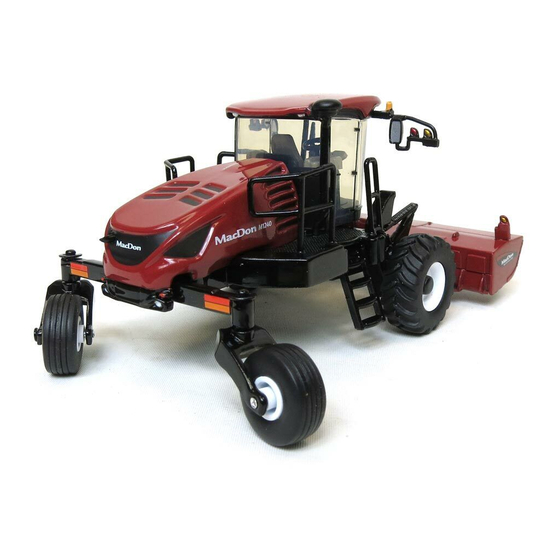
MacDon M1240 Operator's Manual
Self-propelled windrower
Hide thumbs
Also See for M1240:
- Unloading and assembly instructions (170 pages) ,
- Operator's manual (504 pages) ,
- Software update instructions (52 pages)

Related Manuals for MacDon M1240


Summary of Contents for MacDon M1240
- Page 1 M1240 Self-Propelled Windrower Operator’s Manual 214053 Revision A 2017 Model Year Original Instruction The harvesting specialists.
- Page 2 This manual contains instructions for safety, operation, maintenance, and service for the MacDon M1240 ® ™ Self-Propelled Windrower, featuring Dual Direction and CrossFlex rear suspension. Published November 2016 California Proposition 65 Warning Diesel engine exhaust and some of its constituents are known to the State of California to cause cancer, birth defects, and other reproductive harm.
- Page 3 This instruction manual contains information on the MacDon M1240 Self-Propelled Windrower, which when coupled with one of MacDon’s R85 Rotary Disc Headers, A40-D Auger Headers, or D1 Series Draper Headers, provides a package designed to cut and lay a variety of crops into fluffy, uniform windrows.
- Page 4 Serial Number If you require MacDon technical assistance, please have the machine’s serial numbers recorded and ready before you call. Record the model number, model year, and serial number of the windrower and engine on the lines below. The windrower serial number plate (A) is located on the left side of the main frame near the walking beam.
-
Page 5: Table Of Contents
TABLE OF CONTENTS Introduction ............................i Serial Number ..........................ii Safety ..............................1 Safety Alert Symbols........................1 Signal Words........................... 2 General Safety ..........................3 Maintenance Safety ......................... 5 Hydraulic Safety ..........................6 Tire Safety............................7 Battery Safety..........................8 Welding Precaution.......................... 9 Engine Safety .......................... - Page 6 TABLE OF CONTENTS 3.10 Cab Temperature ........................... 60 3.10.1 Heater Shut-Off Valve......................60 3.10.2 Air Distribution ........................60 3.10.3 Climate Controls ........................61 3.11 Operator Amenities ........................62 3.12 Radio ............................64 ® 3.12.1 AM/FM/CD/USB Radio with Bluetooth Wireless Technology ............ 64 ®...
- Page 7 TABLE OF CONTENTS Operating the Windrower....................... 110 4.3.1 Operational Safety ........................ 110 4.3.2 Break-in Period ........................111 4.3.3 Preseason Checks/Annual Service..................111 Air Conditioning Compressor Coolant Cycling..............112 4.3.4 Daily Checks and Maintenance ....................112 Filling Fuel Tank......................113 Filling the Diesel Exhaust Fluid (DEF) Tank ..............113 Checking Engine Oil Level....................
- Page 8 TABLE OF CONTENTS Engaging and Disengaging the Header ................185 Reversing the Header ....................185 4.5.4 Adjusting Header Angle ......................186 Checking Self-Locking Center-Link Hook.................187 4.5.5 Setting Cutting Height......................189 4.5.6 Double Windrowing .......................189 Double Windrow Attachment (DWA) Deck Position ............190 Double Windrow Attachment (DWA) Conveyor Speed ............190 4.5.7 Swath Roller Operation......................191 4.5.8...
- Page 9 TABLE OF CONTENTS Maintenance and Servicing ........................235 Recommended Fuel, Fluids, and Lubricants ...................235 5.1.1 Storing Lubricants and Fluids ....................235 5.1.2 Fuel Specifications ........................235 5.1.3 Lubricants, Fluids, and System Capacities ................236 5.1.4 Filter Part Numbers .......................237 Windrower Break-In Inspections and Maintenance Schedule ............238 5.2.1 Break-in Inspections ......................239 5.2.2...
- Page 10 TABLE OF CONTENTS Cleaning Left Cooling Module ..................272 Cleaning Right Cooling Module..................275 Every 250 Hours or Annually ......................278 5.9.1 Changing Engine Oil......................278 Draining Engine Oil ......................278 Replacing Engine Oil Filter .....................278 Adding Engine Oil ......................279 5.9.2 Maintaining Engine Air Filters....................280 Removing Engine Primary Air Filter.................280 Installing Engine Primary Air Filter ..................281 Cleaning Primary Air Filter....................283...
- Page 11 TABLE OF CONTENTS 5.13.3 Air Conditioning Evaporator ....................313 Removing Air Conditioning (A/C) Cover................313 Cleaning Air Conditioning (A/C) Evaporator Core .............314 Installing Air Conditioning (A/C) Cover................315 5.13.4 Checking Engine Coolant Strength ..................316 5.14 Maintenance as Required......................318 5.14.1 Seat Belts ..........................318 5.14.2 Draining Fuel Tank ........................318 5.14.3 Draining the Diesel Exhaust Fluid (DEF) Tank .................319...
- Page 12 TABLE OF CONTENTS 6.3.2 Towing Harness ........................356 6.3.3 Ballast ..........................356 Troubleshooting ..........................359 Engine Troubleshooting ........................359 Electrical Troubleshooting ......................364 Hydraulics Troubleshooting ......................366 Header Drive Troubleshooting .......................367 Traction Drive Troubleshooting ......................368 Steering and Ground Speed Control Troubleshooting..............370 Cab Air Troubleshooting........................371 Operator’s Station Troubleshooting ....................375 Reference ............................377 Torque Specifications ........................377 8.1.1...
-
Page 13: Safety
1 Safety 1.1 Safety Alert Symbols This safety alert symbol indicates important safety messages in this manual and on safety signs on the machine. This symbol means: • ATTENTION! • BECOME ALERT! • YOUR SAFETY IS INVOLVED! Carefully read follow safety message accompanying this symbol. -
Page 14: Signal Words
SAFETY 1.2 Signal Words Three signal words, DANGER, WARNING, and CAUTION, are used to alert you to hazardous situations. The appropriate signal word for each situation has been selected using the following guidelines: DANGER Indicates an imminently hazardous situation that, if not avoided, will result in death or serious injury. WARNING Indicates a potentially hazardous situation that, if not avoided, could result in death or serious injury. -
Page 15: General Safety
SAFETY 1.3 General Safety CAUTION The following are general farm safety precautions that should be part of your operating procedure for all types of machinery. Protect yourself. • When assembling, operating, and servicing machinery, wear all protective clothing and personal safety devices that could be necessary for job at hand. - Page 16 SAFETY • Wear close-fitting clothing and cover long hair. Never wear dangling items such as scarves or bracelets. • Keep all shields in place. NEVER alter or remove safety equipment. Make sure driveline guards can rotate independently of shaft and can telescope freely. •...
-
Page 17: Maintenance Safety
SAFETY 1.4 Maintenance Safety To ensure your safety while maintaining machine: • Review operator’s manual and all safety items before operation and/or maintenance of machine. • Place all controls in Neutral, stop the engine, set the park brake, remove the ignition key, and wait for all moving parts to stop before servicing, adjusting, and/or repairing. -
Page 18: Hydraulic Safety
SAFETY 1.5 Hydraulic Safety • Always place hydraulic controls Neutral before dismounting. • Make sure that all components in hydraulic system are kept clean and in good condition. • Replace any worn, cut, abraded, flattened, or crimped hoses and steel lines. •... -
Page 19: Tire Safety
SAFETY 1.6 Tire Safety WARNING • Service tires safely. • A tire can explode during inflation which could cause serious injury or death. • Follow proper procedures when mounting a tire on a wheel or rim. Failure to do so can produce an explosion that may result in serious injury or death. -
Page 20: Battery Safety
SAFETY 1.7 Battery Safety WARNING • Keep all sparks and flames away from batteries, as a gas given off by electrolyte is explosive. • Ventilate when charging in enclosed space. Figure 1.16: Safety around Batteries WARNING • Wear safety glasses when working near batteries. •... -
Page 21: Welding Precaution
SAFETY 1.8 Welding Precaution WARNING It is very important that correct procedures be followed when welding anything connected to the windrower. If procedures are not followed, it could result in severe damage to sensitive, expensive electronics. Even if complete failure of a module doesn’t happen immediately, it is impossible to know what effect high current could have with regard to future malfunctions or shorter lifespan. - Page 22 SAFETY • Firewall extension module (two connectors: P235 and P236) (A) Location: Behind cab, near lift fan block To disconnect the connectors, use a small 1/8–1/4 in. blade screwdriver to insert into the connector’s locking tab. Gently pry upward (no more than 1/4 in.) to unlock the connector tab, and pull the connector away from the module.
- Page 23 SAFETY NOTE: Several of the remaining connectors are circular Deutsch connectors. To disconnect, rotate outer collar of connector counterclockwise. • Cab connectors (two round connectors: C1, C2) (A) Location: Under cab Figure 1.24: Cab Connectors • Roof connectors (four connectors: C10, C12, C13, C14) (A) Location: Under cab at base of left cab post Figure 1.25: Roof Connectors...
- Page 24 SAFETY • Engine harness (two round connectors: C30, C31) (A) Location: Inside left frame rail, at rear of windrower Figure 1.27: Engine Harness • Air conditioning (A/C) box connectors (two connectors: C15, C16) (A) Location: Rear of A/C box Figure 1.28: AC Box Connectors •...
- Page 25 SAFETY IMPORTANT: To reconnect circular Deutsch connectors without bending the pins, the connectors must be pre-aligned before attempting to reconnect. To align the connectors: 1. Observe the channel cuts and mating channel protrusions on the inner part of the circular walls of the connectors. 2.
-
Page 26: Engine Safety
SAFETY 1.9 Engine Safety WARNING Do NOT use aerosol types of starting aids such as ether. Such use could result in an explosion and personal injury. CAUTION • On initial start-up of a new, serviced, or repaired engine, always be ready to stop the engine in order to stop an over-speed. -
Page 27: Engine Electronics
SAFETY 1.9.2 Engine Electronics WARNING Tampering with electronic system installation or original equipment manufacturer (OEM) wiring installation can be dangerous and could result in personal injury or death and/or engine damage. WARNING Electrical Shock Hazard. The electronic unit injectors use DC voltage. The engine control module (ECM) sends this voltage to electronic unit injectors. -
Page 28: Safety Signs
SAFETY 1.10 Safety Signs • Keep safety signs clean and legible at all times. • Replace safety signs that missing become illegible. • If original parts on which a safety sign was installed are replaced, be sure repair part also bears current safety sign. -
Page 29: Safety Sign Locations
SAFETY 1.11 Safety Sign Locations Figure 1.31: Safety Sign Locations 214053 Revision A... - Page 30 SAFETY Table 1.1 Safety Sign Locations MD Part Number Safety Sign Description 166234 Decal – Warning (training seat and seat belts) 166425 Decal – Danger 166438 Decal – Header lock, 2 panel (LH) 166439 Decal – Header lock, 2 panel (RH) 166454 Decal –...
-
Page 31: Understanding Safety Signs
SAFETY 1.12 Understanding Safety Signs MD #166234 Run-over hazard WARNING • The training seat is provided for an experienced Operator of the machine when a new Operator is being trained. • The training seat is not intended as a passenger seat or for use by children. - Page 32 SAFETY MD #166438 Crushing hazard DANGER • Rest header on ground or engage safety props before going under unit. Figure 1.34: MD #166438 MD #166439 Crushing hazard DANGER • Rest header on ground or engage safety props before going under unit. Figure 1.35: MD #166439 214053 Revision A...
- Page 33 SAFETY MD #166454 General hazard pertaining machine operation and servicing. CAUTION • Read the operator’s manual and follow all safety instructions. If you do not have a manual, obtain one from your Dealer. • Do not allow untrained persons to operate the machine. •...
- Page 34 SAFETY MD #166457 General hazard pertaining machine operation and servicing CAUTION To avoid injury or death from improper or unsafe machine operation: • Read the operator’s manual and follow all safety instructions. If you do not have a manual, obtain one from your Dealer.
- Page 35 • Use slow moving vehicle emblem and flashing warning Figure 1.38: MD #166463 lights unless prohibited by law. • If width of attached header impedes other vehicle traffic, remove header and install MacDon approved weight box. Refer to operator’s manual for safe procedure to tow header. MD #166824 Hot fluid under pressure and fluid fill rate...
- Page 36 SAFETY MD #166829 Weight balance caution DANGER • Weight on the tail wheels should be greater than 1179 kg (2600 lb.) with the windrower positioned in the cab-forward direction. • Ensure recommended rear ballast kits are installed for proper machine balance. When operating in hilly conditions, additional rear ballast kits may be required.
- Page 37 SAFETY MD #166835 Explosion hazard WARNING • Prevent serious bodily injury caused by explosive battery gases. • Keep sparks and flames away from the battery. • Refer to operator’s manual for battery boosting and charging procedures. Figure 1.43: MD #166835 MD #166836 Battery acid hazard WARNING...
- Page 38 SAFETY MD #166837 Rotating fan hazard DANGER • To avoid injury, stop the engine and remove the key before opening engine hood. Figure 1.45: MD #166837 MD #166838 Hot surface hazard WARNING • To avoid injury, keep a safe distance from hot surface. Figure 1.46: MD #166838 214053 Revision A...
- Page 39 SAFETY MD #166839 Pinch point hazard WARNING • To avoid injury, stop the engine and remove the key before opening engine hood. Figure 1.47: MD #166839 MD #166843 Steering control WARNING To avoid serious injury or death from loss of control: •...
-
Page 41: Product Overview
Diesel exhaust fluid; also called AdBlue in Europe, and AUS 32 in Australia DEF supply module Pump that supplies diesel exhaust fluid through system Dosing module MacDon D130XL, D135XL, D140XL, and D145XL rigid draper headers for D1XL Series header windrowers. Double knife... - Page 42 Knife A cutting device which uses a reciprocating cutter (also called a sickle) M1 Series windrower MacDon M1170 and M1240 self-propelled windrowers Mechanical deck shift Not applicable An internally threaded fastener that is designed to be paired with a bolt N-DETENT The slot opposite the NEUTRAL position on operator’s console...
- Page 43 PRODUCT OVERVIEW Term Definition The product of a force X lever arm length, usually measured in Newton-meters (N·m) Torque or foot-pounds (ft·lbf) A tightening procedure where fitting is assembled to a precondition (finger tight) and Torque angle then nut is turned farther a number of degrees to achieve its final position The relationship between assembly torque applied to a piece of hardware and axial Torque-tension load it induces in bolt or screw...
-
Page 44: Specifications
PRODUCT OVERVIEW 2.2 Specifications Engine Cummins QSB-6.7L CM2350 6 cylinder tier 4 final Type turbo diesel (B20 bio-diesel approved) Displacement 6.7 L (409 cu.in.) Rated 185 kW (248 hp) @ 2200 rpm Power Peak 196 kW (263 hp) @ 2000 rpm Maximum rpm (no load) 2300 Idle rpm... - Page 45 PRODUCT OVERVIEW Header Drive Pump Piston, 105.5 cc (6.44 cu. in.) Knife/Disc Max pressure 41,369 kPa (6000 psi) 0–272.5 L/min (72 gpm) Flow Pump Gear, 25.2 cc (1.54 cu. in.) Reel Max pressure 23,993 kPa (3480 psi) Flow 75.7 L/min (20 gpm) Pump Gear, 19.3 cc (1.18 cu.
- Page 46 PRODUCT OVERVIEW Two speakers, antenna, microphone and Radio ® AM/FM/CD/USB/Bluetooth radio factory installed Sun shades Front and rear Deluxe Cab Package (in addition to Base Cab) Leather, adjustable air ride suspension, seat belt, Operator heated/cooled, lateral isolation, adjustable front Seat cushion Training Leather, folding, cab mounted, seat belt...
- Page 47 PRODUCT OVERVIEW NOTE: Specifications and design are subject to change without notice or obligation to revise previously sold units. 214053 Revision A...
-
Page 48: Windrower Dimensions
PRODUCT OVERVIEW 2.3 Windrower Dimensions Figure 2.1: Windrower Dimensions A - 3304 mm (130-3/32 in.) B - 4290 mm (168-7/8 in.) C - 5752 mm (226-7/16 in.) D - 4070 mm (160-1/4 in.) E - 1160 mm (45-11/16 in.) F - 3480 mm (137-1/32 in.) G - 3449 mm (135-13/16 in.) H - 3422 mm (134-3/4 in.) J - 3856 mm (151-13/16 in.) (Max) -
Page 49: Component Location
PRODUCT OVERVIEW 2.4 Component Location Figure 2.2: Front Cab-Forward View A - Header Lift Leg B - Header Float Springs C - Operator’s Station D - Windshield Wiper E - Turn Signal / Hazard Lights F - Tail Lights Engine-Forward G - Field/Road Lights H - Handholds J - Mirror... - Page 50 PRODUCT OVERVIEW Figure 2.3: Rear Cab-Forward View A - Caster Wheel B - Walking Beam C - Tail Lights - Cab-Forward D - Engine Compartment Hood E - Windshield Wiper F - Field Lights G - Turn Signal/Hazard Lights H - Field/Road Lights J - Mirror K - Door L - Drive Wheel...
-
Page 51: Operator's Station
3 Operator’s Station The operator’s station is designed for operating the windrower in a cab-forward mode (working mode) or in engine-forward mode (transport mode). The operator’s station, which includes the seat, console, and steering column, pivots 180 degrees so that the Operator maintains access to the windrower controls and gauges regardless of the direction of travel. - Page 52 OPERATOR’S STATION 2. Adjust only fore-aft as follows: a. Loosen nuts (A) under console. b. Move console as required. c. Tighten nuts (A). Figure 3.3: Operator Console Fore-Aft 214053 Revision A...
-
Page 53: Operator Presence System
OPERATOR’S STATION 3.2 Operator Presence System The Operator Presence System is a safety feature designed to deactivate selected systems or sound an alarm when the Operator is not seated at the operator’s station. These systems include: • Header drive; refer to 3.2.1 Header Drive, page 41 •... -
Page 54: Operator's Seat Adjustments
OPERATOR’S STATION 3.3 Operator’s Seat Adjustments The operator’s seat has several adjustments. Refer to the following sections for a description—and the location—of each adjustment. Some seat features are only available with the deluxe cab option. 3.3.1 Armrest Raise armrest for easier access to seat. Lower armrest after seat belt is buckled. -
Page 55: Armrest Angle
OPERATOR’S STATION 3.3.2 Armrest Angle Use controls to adjust angle of armrest. • Rotate knob (A) clockwise to increase armrest angle. • Rotate knob counterclockwise decrease armrest angle. Figure 3.5: Operator’s Seat Armrest Angle Controls 3.3.3 Suspension and Height Use controls to adjust the seat’s suspension stiffness and height. •... -
Page 56: Fore-Aft Slide Control
OPERATOR’S STATION 3.3.4 Fore-Aft Slide Control Use controls to adjust the seat’s fore-aft position. 1. Pull lever (A) up to release. 2. Move seat forward or rearward. 3. Release lever (A). Figure 3.7: Operator’s Seat Fore-Aft Position Controls 3.3.5 Fore-Aft Isolator Control Use controls to lock the seat’s fore-aft isolator. -
Page 57: Tilt
OPERATOR’S STATION 3.3.6 Tilt Use controls to adjust the seat’s tilt. 1. Pull lever (A) up to release. 2. Position seat back as desired. 3. Release lever (A). Figure 3.9: Operator’s Seat Tilt Controls 3.3.7 Lumbar Support Use controls to adjusts the stiffness of the seat’s back. •... -
Page 58: Vertical Dampener
OPERATOR’S STATION 3.3.8 Vertical Dampener Use controls to adjust the seat’s vertical suspension dampening. • Turn knob (A) counterclockwise to increase vertical dampener. • Turn knob (A) clockwise to decrease vertical dampener. Figure 3.11: Operator’s Seat Vertical Dampener Controls 3.3.9 Cushion Tilt (Deluxe Cab Only) Use controls to adjust the deluxe seat’s cushion tilt. -
Page 59: Cushion Extension (Deluxe Cab Only)
OPERATOR’S STATION 3.3.10 Cushion Extension (Deluxe Cab Only) Use controls to adjust seat cushion extension fore-aft. 1. Pull lever (A) up to release. 2. Move cushion forward or rearward. 3. Release lever (A). Figure 3.13: Deluxe Seat Cushion Extension Controls 3.3.11 Lateral Isolation Lockout (Deluxe Cab Only) Use the controls (A) to lock or unlock the deluxe seat’s lateral isolation lockout. -
Page 60: Heating/Cooling (Deluxe Cab Only)
OPERATOR’S STATION 3.3.12 Heating/Cooling (Deluxe Cab Only) Use the controls to adjust the heating/cooling of deluxe operator’s seat. Seat heating/cooling switch (A) • Press switch forward for COOL • Press switch back for HEAT Heating/cooling high/low/off switch (B) • Press switch up for HIGH •... -
Page 61: Training Seat
OPERATOR’S STATION 3.4 Training Seat A folding wall-mounted training seat (with seat belt) is provided. WARNING • The training seat is provided for use by an experienced machine Operator while training a new Operator. • The training seat is NOT intended as a passenger seat or for use by children. Use the seat belt whenever operating the machine or riding as a Trainer. -
Page 62: Seat Belts
OPERATOR’S STATION 3.5 Seat Belts The windrower is equipped with seat belts on the operator’s and training seats. WARNING The seat belts can help ensure your safety when properly used and maintained. • Before starting the engine, fasten your seat belt, and ensure that the training seat occupant’s seat belt is securely fastened. -
Page 63: Adjusting The Steering Column And Steering Wheel
OPERATOR’S STATION 3.6 Adjusting the Steering Column and Steering Wheel The steering column and steering wheel are adjustable for the operator’s comfort and to make it easier to get in and out of the operator’s seat. To adjust the steering column: 1. -
Page 64: Lighting
OPERATOR’S STATION 3.7 Lighting The field and road light switches are located on the operator’s console. The position of the operator’s station (cab-forward mode or engine-forward mode) automatically determines which lights are active when the lighting mode is selected. The field lights (B) do NOT turn on when the windrower is in engine-forward mode. -
Page 65: Cab-Forward Lighting - Road
OPERATOR’S STATION • Cab-forward road lights (A) with low/high beams • Engine-forward road lights (B) with low/high beams • Inner work lights (C) • Outer work lights (D) NOTE: Work lights (D) are also turned on when the high beams are activated in cab-forward mode. •... -
Page 66: Engine-Forward Lighting - Road
OPERATOR’S STATION • Headlights (A) with low/high beams • Red tail lights (B) • Amber turn signals/hazard lights (C) on mirror supports • Work lights (D) turn on only when high beams are on in cab-forward mode Figure 3.24: Windrower Lighting – Top View 3.7.3 Engine-Forward Lighting –... - Page 67 OPERATOR’S STATION • Engine-forward headlights (A) with low/high beams • Red tail lights (B) on the mirror supports • Amber turn signals/hazard lights (C) on mirror supports • Amber turn signals and hazard lights (A) on mirror supports (viewed from the front) •...
-
Page 68: Tail/Beacon Lighting
OPERATOR’S STATION 3.7.4 Tail/Beacon Lighting The beacons (A) are functional when the IGNITION is ON and the BEACON button (B) is selected. NOTE: In some areas, the law requires the use of beacon lights when driving on the road. Figure 3.27: Windrower Lighting – Top View Figure 3.28: Beacon Light Button 214053 Revision A... -
Page 69: Turn Signal / Hazard Lighting
OPERATOR’S STATION 3.7.5 Turn Signal / Hazard Lighting The following lights are on when the LEFT and RIGHT turn signal switches (A) are pressed. Press to turn lights off. • Amber turn signal lights (C) which are visible from both front and rear. -
Page 70: Windshield Wipers
OPERATOR’S STATION 3.8 Windshield Wipers The windshield wiper controls are located on the operator console. The illustration shows the controls in cab-forward mode. Button (A) activates the front (cab-forward) wiper, and button (B) activates the rear wiper. One window washer button (C) applies washer fluid to both the front and rear wipers as follows: •... -
Page 71: Rear View Mirrors
OPERATOR’S STATION 3.9 Rear View Mirrors Two outside-mounted adjustable mirrors (A) provide a rear view when the windrower is in cab-forward mode. A single interior-mounted mirror (B) provides a rear view in the engine-forward mode. The mirror/light assemblies (A) are designed to fold back if accidentally struck. -
Page 72: Cab Temperature
OPERATOR’S STATION 3.10 Cab Temperature The cab environment is controlled by a climate control system that provides clean air-conditioned or heated air. The heater/evaporator/blower assembly is located under the cab floor and is accessible from beneath the windrower. 3.10.1 Heater Shut-Off Valve A shut-off valve (A) at the engine allows the cab heater to be isolated from the engine coolant. -
Page 73: Climate Controls
OPERATOR’S STATION 3.10.3 Climate Controls Auto fan speed switch (A) Sets the climate control system to auto mode, which automatically adjusts the fan speed to maintain the set point temperature. Blower control toggle switch (B) Controls the blower speed. Overrides auto-fan control. •... -
Page 74: Operator Amenities
OPERATOR’S STATION 3.11 Operator Amenities The operator’s station includes the following amenities: Operator’s console • Auxiliary power outlets (A) • USB jack (B) • Utility tray under armrest (C) • Utility tray (D) • Cup holder (E) Figure 3.38: Console Window shades Retractable window shades (A) are located at the front and rear windows. - Page 75 OPERATOR’S STATION Coat hook A coat hook (A) is located above the training seat, to the left of the Operator. Figure 3.41: Coat Hook 214053 Revision A...
-
Page 76: Radio
OPERATOR’S STATION 3.12 Radio ® The M1240 Self-Propelled Windrower comes equipped with an AM/FM/CD/USB/Bluetooth radio. The following ® procedures describe how to activate and pair Bluetooth devices with the radio. ® 3.12.1 AM/FM/CD/USB Radio with Bluetooth Wireless Technology A radio (A) and two speakers (B) are factory-installed in the cab headliner. -
Page 77: Pairing A Bluetooth ® Device
OPERATOR’S STATION ® Pairing a Bluetooth Device ® The installed radio allows the operator to pair a Bluetooth phone or audio device. Before proceeding, check that ® ® Bluetooth is enabled and radio has been set to DISCOVER mode. Refer to Activating Bluetooth Feature, page... -
Page 78: Horn
OPERATOR’S STATION 3.13 Horn The horn is activated by pushing button (A) located on the operator console. Sound the horn three times prior to starting the engine. The horn is located under the front left corner of the cab floor when facing cab-forward. Figure 3.45: Operator Console 214053 Revision A... -
Page 79: Engine Controls
OPERATOR’S STATION 3.14 Engine Controls The following engine controls are conveniently located on the operator’s console. Ignition switch • ACC (A): The windrower’s electrical accessories are turned ON without starting the engine • OFF (B): All electrical systems OFF • RUN (C): Engine run position •... -
Page 80: Using Eco Engine Control (Eec)
OPERATOR’S STATION 3.14.1 Using Eco Engine Control (EEC) Eco Engine Control (EEC) is useful in lighter crop conditions that do not require the maximum engine rpm. The reduced engine speed lowers fuel consumption, noise levels, and exhaust emissions in addition to reducing engine wear. -
Page 81: Windrower Controls
OPERATOR’S STATION 3.15 Windrower Controls Console controls: Turn signals (A) – Activates turn signals on windrower and header. • Push-ON/Push-OFF (activating the hazard switch also cancels the turn signal) Ground speed lever (GSL) (B) – Controls speed and direction of movement. •... -
Page 82: Header Controls
OPERATOR’S STATION 3.16 Header Controls All header controls are conveniently located on the operator’s console and on the ground speed lever (GSL) handle. NOTE: Some controls are optional equipment and may not be present in your unit. Some controls may be installed, but are not functional for certain headers. -
Page 83: Ground Speed Lever (Gsl) Switches
OPERATOR’S STATION 3.16.3 Ground Speed Lever (GSL) Switches The switches on the GSL (A) control the most common header functions. Figure 3.53: Ground Speed Lever (GSL) GSL controls — front • One-Touch-Return position switch (A) • One-Touch-Return position switch (B) •... -
Page 84: Header Position Six-Way Switch
OPERATOR’S STATION GSL controls — rear • Rear select switch (A) • Rear scroll wheel (B) Figure 3.55: GSL Function Groups Header Position Six-Way Switch • To lower header slowly, press (A) lightly. • To lower header quickly, press (A) fully. •... -
Page 85: Reel Position Four-Way Switch
OPERATOR’S STATION Reel Position Four-Way Switch The reel position button performs different functions depending on the attached options. For specific operating instructions, refer to the following sections: • Reel fore-aft position and height on draper headers: • 4.6.2 Adjusting Reel Fore-Aft Position, page 194 •... -
Page 86: One-Touch-Return Buttons (A, B, C)
OPERATOR’S STATION One-Touch-Return Buttons (A, B, C) One-Touch-Return buttons save header configuration settings and serve as presets for quickly returning the header to specific settings. The One-Touch-Return buttons A, B, and C always save header height settings, but the following settings can also be saved depending on the header type: •... -
Page 87: Console Header Buttons
OPERATOR’S STATION Pressing a programmed A, B or C button opens a run screen that shows the corresponding letter (A) on the screen for the preset. Figure 3.60 3.16.4 Console Header Buttons The console header buttons (A) adjust the following header functions: •... -
Page 88: Deck Shift / Float Presets
OPERATOR’S STATION Deck Shift / Float Presets Draper header with deck shift option • Controls the draper deck position for double windrowing with a draper header. • Set header float for each deck position. Refer to Setting the Float, page 182. -
Page 89: Conveyer Speed Adjustment Buttons
OPERATOR’S STATION Conveyer Speed Adjustment Buttons Header, or DWA, draper speed is adjusted by pressing switch (A) to increase the speed, or pressing switch (B) to decrease the speed. Draper speed can be adjusted in either manual or auto modes. Refer to 4.6.6 Adjusting Draper Speed, page 202 for more information. -
Page 90: Harvest Performance Tracker (Hpt) Display
OPERATOR’S STATION 3.17 Harvest Performance Tracker (HPT) Display The HPT display settings are preset at the factory. This section explains how to adjust the settings. 3.17.1 Harvest Performance Tracker (HPT) Screen Layout The appearance and functions of the HPT depend on the type of header attached. Figure 3.66: Run Screen 1 (Draper Header Shown) A - Left Gauge Cluster B - Header Information... - Page 91 OPERATOR’S STATION The HPT display is separated into the following three zones: Left gauge cluster • Ground speed • Maximum ground speed • Engine rpm • Eco engine control (EEC) active/inactive • High exhaust system temperature (HEST) light • Inhibit status •...
- Page 92 OPERATOR’S STATION Current header position • Displays basic header functions: height, and angle Figure 3.69: Current Header Position Telltales • Telltales (A) indicate an engine or windrower fault • Telltales are amber or red in color accompanied by a symbol for the fault •...
-
Page 93: Navigating The Harvest Performance Tracker (Hpt) Display
OPERATOR’S STATION 3.17.2 Navigating the Harvest Performance Tracker (HPT) Display Scroll Knob, Scroll Wheel, and Select Button Turning the scroll knob (A) on the Harvest Performance Tracker (HPT) highlights the available options within a menu and increases/decreases the available settings. Pushing the scroll knob selects functions or menu items. Scroll and select functions are duplicated on the ground speed lever (GSL) controls. -
Page 94: Home, Back, And Select Buttons
OPERATOR’S STATION Home, Back, and Select Buttons • Press the BACK button (A) on the Harvest Performance Tracker (HPT) to return to the previous level within the menu structure. • Press the HOME button (B) on the HPT to return to the last selected run screen (or header disengaged screen). -
Page 95: Quickmenu System
OPERATOR’S STATION QuickMenu System The QuickMenu system allows you to change certain windrower and header functions directly on the screen. 1. Press the scroll knob (A) on the Harvest Performance Tracker (HPT) or the SELECT button (B) on the ground speed lever (GSL) while in any run screen to open the QuickMenu system. -
Page 96: Main Menu
OPERATOR’S STATION Main Menu To display the main menu and select functions, follow these steps: 1. Press soft key 5 (A) to open the main menu. 2. Use the Harvest Performance Tracker (HPT) scroll knob (B) or the ground speed lever (GSL) scroll wheel (not shown) to place the red cursor (C) over the icon you want to select. - Page 97 OPERATOR’S STATION Setup: Icon (A) displays the following submenu icons: • Display settings (B) • Windrower settings (C) • Header settings (D) • One-Touch-Return settings (E) Figure 3.81: Settings Icon and Settings Submenu Icons Windrower Settings: Icon (A) displays the following submenu icons: NOTE: The F3 shortcut button on the operator’s console also...
- Page 98 OPERATOR’S STATION After the header is selected, the HEADER SETUP menu opens, which includes: • Cut width • Raise/lower rates • Attachments Figure 3.84: Header Setup Menu Screen Settings: Icon (A) displays the following submenu icons: • Brightness and volume (B) •...
- Page 99 OPERATOR’S STATION Maintenance: Icon opens maintenance menu list (B). Figure 3.87: Maintenance Icon and Maintenance Menu List Diagnostics: Icon displays following submenu icons: • Windrower fault codes (B) • Engine fault codes (C) • Inputs/outputs (D) • CAN network (E) Figure 3.88: Diagnostics Icon and Diagnostics Submenu Icons Engine Aftertreatment: Icon (A)
-
Page 100: Faults And Telltales
OPERATOR’S STATION Faults and Telltales Faults and telltales—displayed on the Harvest Performance Tracker (HPT)—provide important information about the windrower and the engine. Telltales (A) include a symbol indicating the affected area (refer to 4.2 Symbol Definitions, page 106) and a short description of the fault (B). •... -
Page 101: Setting Up The Harvest Performance Tracker (Hpt) Screen
OPERATOR’S STATION If multiple faults are detected, the number of faults will appear in the corner of the telltale icon (A). Figure 3.91: Telltale Icon (Multiple Faults Detected) Using the HPT scroll/select knob, select the question mark symbol next to the short description to display a detailed description of the fault. - Page 102 OPERATOR’S STATION 1. Navigate to the SETTINGS Menu with soft key 5 and the Harvest Performance Tracker (HPT) scroll knob. Refer to 3.17.2 Navigating the Harvest Performance Tracker (HPT) Display, page 81 if required. 2. Scroll to the SCREEN icon (A) and select it. 3.
-
Page 103: Setting Time And Date
OPERATOR’S STATION 2. Scroll to the SCREEN icon (A) and select it. 3. Scroll to the BRIGHTNESS AND VOLUME icon (B), and select it to open adjustment window. Figure 3.96: Brightness and Volume 4. Scroll to the VOLUME option (A) and select it. 5. -
Page 104: Setting Language And Units Of Measure
OPERATOR’S STATION 4. Scroll through the available options on the HPT display, select desired option, and scroll to adjust. Figure 3.99: Time and Date Setting Language and Units of Measure 1. Navigate to the SETTINGS menu with soft key 5 and Harvest Performance Tracker (HPT) scroll knob. -
Page 105: Resetting To Factory Defaults
OPERATOR’S STATION Resetting to Factory Defaults 1. Press soft key 5 (A), and use the Harvest Performance Tracker (HPT) scroll knob (B) or the ground speed lever (GSL) scroll wheel (not shown) to place the red cursor over the SETTINGS icon (C). 2. -
Page 106: Calibrating The Windrower And Header
OPERATOR’S STATION ● HEADER ALARM PRESSURES ● KNIFE ALARM SPEED ● MANUAL (NOT AUTO) KNIFE SPEED MODE ● MANUAL (NOT AUTO) REEL SPEED MODE ● MANUAL (NOT AUTO) DRAPER SPEED MODE ● ALL FUNCTIONS UNLOCKED ● ALL SENSORS ENABLED ● CUT WIDTH ●... - Page 107 OPERATOR’S STATION 1. Start the engine, and engage the header. 2. Press soft key 5 (A) to open the main menu. 3. Use the HPT scroll knob (B) or the ground speed lever (GSL) scroll wheel (not shown) to place the red cursor over the SETTINGS icon (C).
- Page 108 OPERATOR’S STATION 8. Select CALIBRATION WITH HEADER ENGAGED to display the calibration page as shown at right. 9. Press the PLAY button on the screen to begin the calibration process. NOTE: If the engine speed is less than 1500 rpm when you press the PLAY button, the calibration system will accelerate the engine to 1500 rpm.
-
Page 109: Setting Windrower Tire Size
OPERATOR’S STATION NOTE: Press the X button (A) on the screen (or press the HOME, BACK or any GSL button [buttons not shown]) at any time during the calibration process to EXIT calibration without saving. The engine speed will return to the original rpm prior to starting the calibration process. -
Page 110: Activating Control Locks
OPERATOR’S STATION 3.17.6 Activating Control Locks All header functions are factory-set to the unlocked position, but certain functions can be locked to prevent changes. This feature can be used to maintain preferred settings when there are multiple Operators. 1. Press soft key 5 (A) to display the main menu. 2. -
Page 111: Machine Information
OPERATOR’S STATION 3.17.7 Machine Information Pages Selecting the INFORMATION icon (A) from the main menu provides access to the following submenu icons: • Windrower information (B) – Refer to Windrower Information, page • Header information (C) – Refer to Header Information, page 100. -
Page 112: Header Information
OPERATOR’S STATION The windrower information menu displays the following information: • Engine hours (A) • Windrower total hours (B) • Total acres (C) • Windrower total header hours (D) Figure 3.118: Windrower Information Menu Header Information 1. Press soft key 5 (A) to open the main menu. 2. -
Page 113: Software Information
OPERATOR’S STATION The header information menu displays the following information: • Header (A) • Header hours (B) • Total acres (B) • Sub-acres (D) (resettable) NOTE: If you select reset (E), the message RESET YES/NO appears on the display. Select YES to reset the sub-acres to zero and return to the same highlighted sub-acres. -
Page 114: Performance Information
OPERATOR’S STATION The HPT display reports the component make, software ID, and software installation date in the software information menu. In addition, the software versions and make, model, and serial numbers of the following modules are also displayed on the screen: •... -
Page 115: F1 To F4 Function Buttons
OPERATOR’S STATION The performance information menu displays two columns: one column displays the accumulated data over the machine’s lifetime (A) and is not resettable, the other displays the data accumulated per field (B) and is resettable. The performance information menu displays the following information: •... -
Page 117: Operation
4 Operation 4.1 Owner/Operator Responsibilities CAUTION • It is your responsibility to read and understand this manual completely before operating the windrower. Contact your Dealer if an instruction is not clear to you. • Follow all safety messages in the manual and on safety signs on the machine. •... -
Page 118: Symbol Definitions
OPERATION 4.2 Symbol Definitions The following symbols are used to depict functions or reactions of the various instruments and controls. Learn the meaning of these symbols before operating the windrower. 214053 Revision A... -
Page 119: Windrower Operating Symbols
OPERATION 4.2.1 Windrower Operating Symbols These are the symbols used on the console for windrower operation. Figure 4.1: Windrower Operating Symbols A - Signal Lights B - Hazard Lights C - Forward D - Neutral E - Reverse F - Road Lights G - High Beams H - Cab-forward Field Lights J - Blower Speed (Manual Mode) -
Page 120: Harvest Performance Tracker Symbols
OPERATION 4.2.2 Harvest Performance Tracker Symbols Figure 4.2: Harvest Performance Tracker Symbols Knife Header Tilt High Exhaust System Temperature Knife Pressure Header Float Engine rpm Reel DWA Raise Fuel Reel Speed DWA Lower Water in Fuel Reel Height Disc AA - Parking Brake Reel Fore-Aft Disc Pressure... - Page 121 OPERATION Figure 4.3: Harvest Performance Tracker Symbols Acres/Hour Engine Oil Pressure Caution (Yellow) / Danger (Red) Sub Acres Engine Oil Level Function Locked Fuel/Acre Engine Oil Filter Time Fuel/Hour Engine Coolant Level Date Engine Power Kilowatt Engine Air Intake Temperature AA - Alarm Engine Power Horsepower...
-
Page 122: Operating The Windrower
OPERATION 4.3 Operating the Windrower 4.3.1 Operational Safety CAUTION Follow these safety precautions: • Wear close fitting clothing and protective shoes with slip resistant soles. • Remove foreign objects from the machine and surrounding area. • Carry with you any protective clothing and personal safety devices that could be necessary through the day. -
Page 123: Break-In Period
OPERATION 4.3.2 Break-in Period The windrower is ready for normal operation. However, there are several items to check and watch out for during the first 150 hours. DANGER Before investigating an unusual sound or attempting to correct a problem, place ground speed lever (GSL) in N-DETENT, shut off engine, and remove key. -
Page 124: Air Conditioning Compressor Coolant Cycling
OPERATION 6. Check the entire A/C system for leakage at the beginning of each season. 7. Perform annual maintenance. Refer to 5.2 Windrower Break-In Inspections and Maintenance Schedule, page 238. Air Conditioning Compressor Coolant Cycling IMPORTANT: Perform the following steps whenever the machine is first started after storage for more than one week: 1. -
Page 125: Filling Fuel Tank
OPERATION 5. Perform daily maintenance. Refer to 5.2 Windrower Break-In Inspections and Maintenance Schedule, page 238. Filling Fuel Tank Fill fuel tank daily, preferably at the end of the day’s operation to help prevent condensation in the tank. DANGER To avoid bodily injury or death from unexpected startup of the machine, always stop the engine and remove the key from the ignition before leaving the operator’s seat for any reason. -
Page 126: Checking Engine Oil Level
OPERATION 1. Stop engine and remove key from ignition. 2. Clean around filler cap (A). 3. Turn cap (A) counterclockwise until loose and remove cap. NOTE: Filler cap for DEF tank is blue and the nozzle dispenser is smaller than that of the fuel tank. CAUTION Avoid contact with eyes. -
Page 127: Engine Operation
OPERATION 3. Remove the dipstick (A) by turning it counterclockwise to unlock. 4. Wipe the dipstick clean and reinsert it into the engine. 5. Remove the dipstick again and check the oil level. Figure 4.9: Dipstick Location 6. Oil level should be between LOW (L) and HIGH (H). If level is below LOW mark, 1.9 liters (2 US quarts) will raise the level from LOW to HIGH. - Page 128 OPERATION 1. Ensure the cab-forward or engine-forward directional lock (A or B) is engaged at the base of the steering column. Figure 4.11: Direction Locks 2. Move ground speed lever (GSL) (A) into PARK (C). 3. Turn steering wheel until it locks. It may be possible to move the steering wheel slightly in the locked position.
- Page 129 OPERATION 6. Turn IGNITION switch (A) to the ON position, and the Harvest Performance Tracker (HPT) (B) will illuminate. If HPT is still booting up, wait for Wait to Start (WTS) symbol (C) to disappear before trying to start engine. 7.
- Page 130 • Adjust position of operator’s station Operator’s station not locked • Ensure lock is engaged Neutral interlock misadjusted • Contact MacDon Dealer • Fill empty fuel tank No fuel to engine • Replace clogged filter • Check for blocked or damaged fuel lines.
-
Page 131: Programming The Eco Engine Control (Eec)
• Adjust position of operator’s station Operator’s station not locked • Ensure lock is engaged Neutral interlock misadjusted • Contact MacDon Dealer • Fill empty fuel tank No fuel to engine • Replace clogged filter • Check for blocked or damaged fuel lines. -
Page 132: Shutting Down The Engine
OPERATION 1. To open the QuickMenu system while in any run screen, press the scroll knob (A) on the HPT. Figure 4.16: HPT Scroll Knob/Select Button 2. Use the HPT scroll knob to move the red cursor to the ECO THROTTLE LIMIT (A) value. 3. -
Page 133: Engine Temperature
OPERATION IMPORTANT: Before stopping engine, run at low idle for approximately five minutes to cool hot engine parts (and allow turbocharger to slow down while engine oil pressure is available). 1. Lower header. 2. Place ground speed lever (GSL ) (B) into N-DETENT. 3. -
Page 134: Exhaust System Cleaning
OPERATION Exhaust System Cleaning The exhaust aftertreatment system uses diesel exhaust fluid (DEF) and selective catalyst reduction (SCR) technology to reduce the emission of nitrogen oxides (NOx). The process involves injecting DEF (a nitrogenous compound which decomposes into ammonia) into the exhaust over a catalyst. The ammonia reacts with NOx producing harmless nitrogen and water. -
Page 135: Run Screen 3 - Performance Data
OPERATION 4. To select manual SCR conditioning, press soft key 4 (A) next to the MANUAL SCR CONDITIONING icon (B), and hold for 3 seconds. The high exhaust system temperature (HEST) icon (C) appears highlighted under the rpm display during system cleaning. NOTE: The HEST icon also appears during normal operation when exhaust temperature exceeds... -
Page 136: Run Screen 4 - Cooling Data
OPERATION To display the windrower’s performance data: 1. Press soft key 3 (A) on the Harvest Performance Tracker (HPT) to open the PERFORMANCE DATA display. NOTE: Soft keys 1–5 also function as buttons within menus. Figure 4.25: HPT Display Run Screen 4 – Cooling Data Figure 4.26: Run Screen 4 –... -
Page 137: Operating The Windrower
OPERATION To display the windrower’s cooling data: 1. Press soft key 4 (A) on the Harvest Performance Tracker (HPT) to open the COOLING DATA display. NOTE: Soft keys 1–5 also function as buttons within menus. NOTE: The engine fan speed will increase/decrease, depending on cooling requirements. -
Page 138: Adjusting Ground Speed Limit
OPERATION A swing-away platform with stairs (A) is provided on the left side of the windrower to accommodate cab-forward and engine-forward access to the operator’s station as well as several maintenance tasks. Two doors (B) are provided for cab entry and exit in either cab-forward mode or engine-forward mode. -
Page 139: Driving Forward In Cab-Forward Mode
OPERATION 2. Use the HPT scroll knob to move the red cursor to the GROUND SPEED LIMIT selectable area (A). 3. Press the HPT scroll knob to select, and scroll to adjust the ground speed limit values. NOTE: Ground speed limit is also changed by simultaneously pressing the GSL shift button on back of GSL and scrolling. -
Page 140: Driving In Reverse In Cab-Forward Mode
The windrower can be equipped with an automatic steering system for use in the field. An automated steering system is available as an option and can be installed by a MacDon Dealer. The GSL has been pre-wired at the factory with a switch. Refer to 6.1.1 Automated Steering... -
Page 141: Driving Forward In Engine-Forward Mode
OPERATION 3. Steer as shown. Figure 4.35: Cab-Forward Mode Driving Forward in Engine-Forward Mode In the engine-forward mode, the operator’s station is facing toward the engine. If necessary, swivel operator’s station to engine-forward position as follows: Figure 4.36: Engine-Forward – Seat Faces Engine 1. -
Page 142: Driving In Reverse In Engine-Forward Mode
OPERATION 5. Use the Harvest Performance Tracker (HPT) to adjust the maximum speed setting to 43 km/h (27 mph). Refer Adjusting Ground Speed Limit, page 126. 6. Slowly push throttle (A) to full forward (operating speed). CAUTION Check to be sure all bystanders have cleared the area. 7. -
Page 143: Spin Turning
OPERATION 1. Move throttle lever (A) to a mid-range position. NOTE: Reversing in low speed range and at reduced engine speed is recommended since steering will be less sensitive than at higher speed settings. 2. Move the ground speed lever (GSL) (B) rearward to desired speed. -
Page 144: Stopping
OPERATION Stopping WARNING Do NOT move ground speed lever rapidly back to NEUTRAL. You may be thrown forward by sudden stop and wheels may skid reducing steering control. Always wear seat belt when operating windrower. To stop the windrower: 1. Anticipate stopping and SLOWLY return the ground speed lever (GSL) (A) to NEUTRAL and into N-DETENT. -
Page 145: Transporting
Driving on Road in Engine-Forward Mode The M1240 Self-Propelled Windrower is designed to be driven on the road with the engine facing forward to provide better visibility for the Operator and improved stability for the machine. The windrower is also capable of being driven on the road in cab-forward mode, with or without a header attached, but at a reduced speed, under restricted conditions, and only for models sold in North America. - Page 146 OPERATION 8. Press switch (A) for road lights. Always use these lights when driving machine on roads. a. Press switch (B) for high/low lights as required when other vehicles are approaching. IMPORTANT: Do NOT use field lights on roads; other drivers may be confused by them.
- Page 147 (SLOW DOWN) with an audible alert. Move GSL closer to NEUTRAL to reduce speed. With header removed, steering control is reduced if weight is not added to drive wheels. If you must drive the windrower without header or MacDon weight system: • Do NOT exceed minimum speed setting.
-
Page 148: Driving On Road In Cab-Forward Mode
Driving on Road in Cab-Forward Mode The M1240 Self-Propelled Windrower is capable of being driven on the road in cab-forward mode, with or without a header attached, but at a reduced speed, under restricted conditions, and only for models sold in North America. - Page 149 OPERATION 7. Press switch (A) to turn on lights. Always use these lights on roads to provide warning to other vehicles. a. Use high/low switch (B) as required when other vehicles are approaching. b. Do NOT use field lights on roads, to avoid confusing other drivers.
-
Page 150: Towing Header With Windrower
Towing Header with Windrower The windrower can be used to tow a MacDon draper header that has the slow speed transport option installed. Ensure the optional weight box or an approved header transporter is installed on the windrower to transfer weight to the lift arms. - Page 151 OPERATION CAUTION • To tow a header with an M1240 Self-Propelled Windrower, the header must be equipped with the appropriate equipment to comply with local regulations. • Before towing, verify signal lighting and safety equipment is installed and functioning properly.
- Page 152 OPERATION 2. Convert header to transport mode. Refer to header operator’s manual. 3. Detach header from windrower. Refer to Detaching a D1X or D1XL Series Header, page 163. 4. Remove hairpin (D) and clevis pin (C) securing header support (B) to leg (A). Retain pins for attaching weight box.
-
Page 153: Towing The Windrower (Emergency)
OPERATION 12. Start engine and raise weight box until tow bar is level. Transport the header. Refer to Towing Header with Windrower, page 138 Figure 4.57: Towing a Header Towing the Windrower (Emergency) Towing the windrower is NOT recommended. If the windrower gets stuck, or must be towed onto a truck or trailer, follow these steps: IMPORTANT: •... -
Page 154: Storing The Windrower
OPERATION Disengaging Final Drives Disengage and engage final drives as follows: 1. Remove the two bolts (A) at the center of drive wheel. 2. Remove cap (B) and flip over so that dished side faces in. The cap depresses a pin that disengages the gearbox. - Page 155 OPERATION 10. Lubricate the windrower thoroughly, leaving excess grease on fittings to keep moisture out of bearings. Apply grease to exposed threads and sliding surfaces of components. 11. Remove batteries (refer to Removing a Battery, page 310), bring to full charge, and store in a cool, dry place not subject to freezing.
-
Page 156: Attaching And Detaching Headers
OPERATION 4.4 Attaching and Detaching Headers 4.4.1 A40-D Auger Header Attaching an A40-D Auger Header This procedure is for 2017 and newer A40-D headers equipped with the Auger Header Compatibility kit (MD #B5998). CAUTION To avoid bodily injury or death from unexpected startup of machine, always stop engine and remove key from ignition before leaving operator’s seat for any reason. - Page 157 OPERATION 3. Press HPT scroll knob (A) to highlight QuickMenu options. 4. Rotate HPT scroll knob (A) to highlight the HEADER FLOAT symbol (B) and press to select. Figure 4.62: HPT Display 5. On Float Adjust page, press soft key 3 (A) to remove float.
- Page 158 OPERATION 8. For hydraulic center-link without self-alignment: Relocate pin (A) in frame linkage as required to raise the center-link (B) until the hook is above the attachment pin on the header. IMPORTANT: If the center-link is too low, it may contact the header as the windrower approaches the header for hookup.
- Page 159 OPERATION CAUTION Check to be sure all bystanders have cleared the area. 14. Press the HEADER UP switch (A) to raise header to maximum height. NOTE: If one end of the header does NOT fully raise, rephase the lift cylinders as follows: a.
- Page 160 OPERATION 18. Remove lynch pin from clevis pin (A) in stand (B). 19. Hold stand (B) and remove pin (A). 20. Move stand to storage position by inverting and relocating onto bracket as shown. Reinsert clevis pin (A) and secure with lynch pin. Figure 4.71: Header Stand 21.
-
Page 161: Connecting A40-D Hydraulics
OPERATION NOTE: If not prompted by the HPT display to restore header float, restore header float manually by doing the following: 24. Press rotary scroll knob (A) on HPT to highlight QuickMenu options. 25. Rotate scroll knob (A) to highlight the HEADER FLOAT symbol (B). - Page 162 OPERATION 3. Retrieve hydraulic multicouplers (A) and electrical harness (B) from the header. 4. Route hose/harness bundle toward the windrower through support (C). Figure 4.77: Hydraulics Hoses in Storage Position 5. Insert hose support (A) into hole in the windrower left leg, and route the header hose bundle (B) under the windrower to the hydraulic and electrical couplers.
-
Page 163: Detaching An A40-D Auger Header
OPERATION 11. Remove cover from receptacle (A), and connect electrical harness from header. Figure 4.80: Electrical Connectors 12. Push platform (A) towards the cab until it stops and latch engages. Figure 4.81: Platform: Closed Detaching an A40-D Auger Header DANGER To avoid bodily injury or death from unexpected startup of the machine, always stop the engine and remove the key from the ignition before leaving the operator’s seat for any reason. - Page 164 OPERATION 1. Start engine and press header up button (A) on ground speed lever (GSL) to raise header to maximum height. 2. If one end of the header does NOT raise fully, rephase the cylinders as follows: a. Press and hold the header up (A) switch until both cylinders stop moving.
- Page 165 OPERATION 6. Lower stand (A) by pulling clevis pin (B), inverting stand, and relocating on bracket. Reinsert pin (B) and secure with hairpin. Figure 4.85: Header Stand CAUTION Check to be sure all bystanders have cleared the area. 7. Disengage safety props by turning lever (A) away from header to raise safety prop until lever locks into vertical position.
- Page 166 OPERATION 10. Stop the engine and remove key from ignition. 11. Lift hook release (A) and lift hook (B) off header pin. NOTE: If optional center-link self-alignment kit is installed, lift release (C) and then operate the link lift cylinder with the REEL UP switch on the GSL to disengage the center-link from the header.
-
Page 167: D1X Or D1Xl Series Header
OPERATION 15. Reinstall clevis pin (B) into header support (C) and secure with hairpin (A). Repeat for opposite side. Figure 4.91: Header Support 4.4.2 D1X or D1XL Series Header Attaching Draper Header Supports Draper header supports are required to attach a D1X or D1XL Series Draper Header to the windrower. DANGER To avoid bodily injury or death from unexpected startup of the machine, always stop the engine and remove the key from the ignition before leaving the operator’s seat for any reason. -
Page 168: Attaching A D1X Or D1Xl Series Header
OPERATION 2. Position the draper header support (B) on lift linkage (A), and reinstall clevis pin (C). NOTE: To avoid pin snagging the windrow, install the clevis pin on the outboard side of the draper header support. 3. Secure clevis pin (C) with hairpin (D). 4. - Page 169 OPERATION 2. Remove hairpin (A) from pin (B), and remove pin (B) from header leg. Repeat on the other header leg. CAUTION Check to be sure all bystanders have cleared the area. 3. Start engine. Figure 4.95: Header Leg CAUTION To prevent damage to the header lift linkages when lowering header lift legs without a header or weight box attached to the windrower, ensure the float...
- Page 170 OPERATION 5. Drive the windrower slowly forward until the draper header supports (A) enter the header legs (B). Continue driving slowly forward until lift linkages contact the support plates in the header legs and the header nudges forward. 6. Ensure that lift linkages are properly engaged in header legs and are contacting the support plates.
- Page 171 OPERATION 8. For hydraulic center-link without self-alignment: a. Press HEADER TILT UP or HEADER TILT DOWN cylinder switches on the GSL to extend or retract center-link cylinder until the hook is aligned with the header attachment pin. b. Stop the engine and remove the key. c.
- Page 172 OPERATION 12. Install pin (B) through the header leg (engaging U-bracket in draper header support) on both sides and secure with a hairpin (A). 13. Raise header stand (D) to storage position by pulling spring pin (C) and lifting stand into uppermost position. Release spring pin.
-
Page 173: Connecting D1X Or D1Xl Series Hydraulics
OPERATION Connecting D1X or D1XL Series Hydraulics IMPORTANT: To prevent contamination of the hydraulic system, use a clean rag to remove dirt and moisture from all (fixed and movable) hydraulic couplers. 1. Pull handle (A) on hose management arm (B) rearward to disengage arm from support (C). - Page 174 OPERATION 5. Open left cab-forward side platform. Refer to 5.4.1 Opening Platform, page 246. 6. Retrieve draper drive and reel control multicoupler (A) from hose management arm. 7. Push knob (B) on hydraulic receptacle and pull handle (C) fully away from windrower. 8.
-
Page 175: Detaching A D1X Or D1Xl Series Header
OPERATION Detaching a D1X or D1XL Series Header DANGER To avoid bodily injury or death from unexpected startup of the machine, always stop the engine and remove the key from the ignition before leaving the operator’s seat for any reason. 1. - Page 176 OPERATION 9. Push lock button (B), and pull handle (C) to disengage multicoupler (A). Disconnect the hydraulics from the windrower draper drive/reel lift receptacle. 10. Disconnect electrical connector (E). 11. Remove any debris that may have accumulated on the windrower front receptacle, and close cover (D). Figure 4.113: Draper/Reel Multicoupler 12.
- Page 177 OPERATION 16. Pivot hose management arm (B) forward with handle (A), and engage hook (D) into latch (C) on header. Figure 4.116: Hose Management Arm 17. Remove the header leg pin (B) by removing the hairpin (A) from header leg on both sides. 18.
- Page 178 OPERATION 20. Disengage safety prop by turning lever (A) downwards until lever locks into the vertical position. 21. Repeat for the opposite side. Figure 4.119: Disengaging Safety Prop CAUTION Check to be sure all bystanders have cleared the area. 22. Start the engine. 23.
-
Page 179: R85 16-Foot Header
OPERATION Windrowers without self-aligning center-link: 28. Shut off the engine and remove the key. 29. Disconnect center-link by lifting release (B) and lift hook (A) off header. CAUTION Check to be sure all bystanders have cleared the area. 30. Start the engine. Figure 4.121: Hydraulic Center-Link 31. - Page 180 OPERATION 1. Hydraulic center-link without self-alignment: Relocate pin (A) in frame linkage as required to raise the center-link (B) until the hook is above the attachment pin on the header. IMPORTANT: If the center-link is too low, it may contact the header as the windrower approaches the header for hookup.
- Page 181 OPERATION 4. Press HEADER DOWN switch (E) on the ground speed lever (GSL) to fully retract header lift cylinders. 5. For hydraulic center-link with self-alignment: Press the REEL UP switch (B) on the GSL to raise the center-link until the hook is above the attachment pin on the header.
- Page 182 OPERATION 9. For hydraulic center-link without self-alignment: a. Press HEADER TILT UP or HEADER TILT DOWN cylinder switches on the GSL to extend or retract center-link cylinder until the hook is aligned with the header attachment pin. b. Stop the engine and remove the key. c.
- Page 183 OPERATION 13. Install clevis pin (A) through support and foot and secure with hairpin (B). Repeat for opposite side. IMPORTANT: Ensure clevis pin (A) is fully inserted and hairpin is installed behind bracket. Figure 4.132: Header support 14. Disengage safety prop turning lever...
- Page 184 OPERATION NOTE: If not prompted by the HPT display to restore header float, restore header float manually by doing the following: 17. Press rotary scroll knob (A) on Harvest Performance Tracker (HPT) to highlight QuickMenu options. 18. Rotate scroll knob (A) to highlight the HEADER FLOAT symbol (B), and press scroll knob to select.
-
Page 185: Connecting R85 16-Foot Header Hydraulics
Note that these steps are also included in the R85 rotary header operator’s manual. 1. Open the left side platform (A). Refer to 5.4.1 ., page Figure 4.137: M1240 Windrower 2. Route hose bundle (A) from header to under windrower frame. - Page 186 OPERATION 4. Disconnect hose (A) from windrower receptacle (B) Image Tag Expected within Figure Tag Knife Drive Hose and place in storage cup (C) on multicoupler. 5. Refer to the following to connect hydraulic hoses with quick disconnect fittings, and electrical connections to the windrower.
-
Page 187: Detaching R85 16-Foot Header
OPERATION 6. Refer to the following to directly connect the hydraulic hoses to the windrower as shown: a. Use a clean rag to remove dirt and moisture from the couplers. b. Attach the disc pressure hose (A) to fitting on frame and torque to 205–226 N·m (151–167 ft·lbf). - Page 188 OPERATION 3. Engage safety prop on the windrower’s lift cylinder as follows: a. Pull lever (A) and rotate toward header to release, and lower safety prop onto cylinder. b. Repeat for opposite lift cylinder. IMPORTANT: Ensure the safety props engage over the cylinder piston rods.
- Page 189 OPERATION 7. Engage safety prop on the windrower’s lift cylinder as follows: a. Pull lever (A) and rotate toward header to release, and lower safety prop onto cylinder. b. Repeat for opposite lift cylinder. IMPORTANT: Ensure the safety props engage over the cylinder piston rods.
- Page 190 OPERATION CAUTION Check to be sure all bystanders have cleared the area. 11. Start engine and remove header float when prompted by the Harvest Performance Tracker (HPT). NOTE: If not prompted by the HPT to remove float, remove float manually. Refer to Removing and Restoring Float, page 184.
- Page 191 OPERATION 18. Back the windrower slowly away from header. 19. Reinstall clevis pin (A) through support (C) and secure with hairpin (B). Repeat for opposite side. Figure 4.150: Header Support 214053 Revision A...
-
Page 192: Operating With A Header
OPERATION 4.5 Operating with a Header This section describes the operating instructions for the following header types when attached to a MacDon M1240 Self-Propelled Windrower: R85 16-Foot Rotary Header, A40-D Auger Header, D1XL Series Draper Header, or D125 Draper Header. -
Page 193: Using Header Float
OPERATION 4. Disengage safety props by turning lever (A) away from header to raise safety prop until lever locks into vertical position. NOTE: If safety prop will not disengage, raise header to release the prop. 5. Repeat for opposite cylinder. CAUTION Check to be sure all bystanders have cleared the area. -
Page 194: Setting The Float
OPERATION 2. Use the HEADER TILT switches (A) on the ground speed lever (GSL) to set the center-link to the mid-range position (5.0 on the Harvest Performance Tracker [HPT]). 3. If checking float with a draper header attached, set the reel to the normal operating position. - Page 195 OPERATION 3. Press rotary scroll knob (A) on HPT to display the QuickMenu system. 4. Rotate scroll knob (A) to highlight header float icon (B) and press scroll knob to select. Figure 4.156: HPT Run Screen 5. Turn scroll knob (A) to highlight left (B) or right (C) float and press knob (A) to activate selection.
-
Page 196: Removing And Restoring Float
OPERATION 3. Press rotary scroll knob (A) on HPT to display the QuickMenu system. 4. Rotate scroll knob (A) to highlight header float icon (B) and press scroll knob to select. Figure 4.159: HPT Run Screen 5. Turn scroll knob (A) to highlight left (B) or right (C) float and press knob (A) to activate selection. -
Page 197: Header Drive
OPERATION 3. Press soft key 3 (A) to remove or restore the header float. NOTE: If the header float is active, the icon at soft key 3 will say REMOVE FLOAT; if header float has been removed, the icon will say RESTORE FLOAT. -
Page 198: Adjusting Header Angle
OPERATION 1. Press and hold the HEADER DRIVE REVERSE button (A). 2. Press and hold the HEADER ENGAGE switch (B) and pull up on collar (C). 3. Release the HEADER DRIVE REVERSE button (A) to stop the header. 4. Push down to reset the HEADER ENGAGE switch (B) to OFF. -
Page 199: Checking Self-Locking Center-Link Hook
OPERATION Figure 4.165: HPT Display and GSL Adjust the header angle as follows: • To decrease (flatten) header angle, operate the HEADER TILT UP switch (C) on the GSL to retract the cylinder. • To increase (steepen) header angle, operate the HEADER TILT DOWN switch (D) on the GSL to extend the cylinder. - Page 200 OPERATION 1. If a header is attached to the windrower, lower header to the ground. 2. Turn off the engine and remove the key from the ignition. 3. Pull up on handle (A) to release the locking device, and lift the hook off the header pin. Figure 4.166: Center-Link 4.
-
Page 201: Setting Cutting Height
Refer to the MacDon Double Windrow Attachment (DWA) for M1 Series Windrowers Manual for complete setup, operating, and maintenance instructions. The manual is shipped with the DWA kit. -
Page 202: Double Windrow Attachment (Dwa) Deck Position
OPERATION Double Windrow Attachment (DWA) Deck Position 1. Raise and lower DWA deck with REEL UP (A) and REEL DOWN (B) switches on ground speed lever (GSL), or on the operator’s console. Figure 4.172: GSL Figure 4.173: Operator’s Console Draper Controls Double Windrow Attachment (DWA) Conveyor Speed The DWA conveyor speed is adjustable from the operator’s... -
Page 203: Swath Roller Operation
OPERATION The DWA conveyor speed is also adjustable with the reel fore-aft switches on the GSL. Press switch (A) to increase speed or switch (B) to decrease speed. Figure 4.175 4.5.7 Swath Roller Operation The swath roller can be raised by pressing button (A) or lowered by pressing button (B) on the operator’s console. -
Page 204: One-Touch-Return
OPERATION 4.5.8 One-Touch-Return One-Touch-Return allows you to choose and apply three presets to the A, B, and C keys (A) on the ground speed lever (GSL). One-Touch-Return presets can be set to control variables such as height, tilt, reel position, and speeds. Refer to One-Touch-Return Buttons (A, B, C), page Figure 4.177: GSL 4.5.9 Adjusting Header Raise and Lower Rates... - Page 205 OPERATION 4. Use the HPT scroll knob or the GSL scroll wheel to move the red cursor to the HEADER SETTINGS icon (A). 5. Press the HPT scroll knob or GSL SELECT button to display the SET-UP HEADER menu list. NOTE: The F4 shortcut button on the operator’s console also will display the SET-UP HEADER menu list.
-
Page 206: Operating With D1X Or D1Xl Series Headers
4.6 Operating with D1X or D1XL Series Headers The M1240 Self-Propelled Windrower is factory-configured for an R85 16-Foot Rotary Disc Header. Conversion kits are available for D1X and D1XL Series Draper Headers. Contact your MacDon Dealer for details. Refer to Available Options and Attachments. -
Page 207: Leveling The Header
OPERATION 4.6.4 Leveling the Header The windrower lift linkages are factory-set to provide the proper header level, and should not normally require adjustment. If leveling is required, follow these steps: DANGER To avoid bodily injury or death from unexpected startup of the machine, always stop the engine and remove the key from the ignition before leaving the operator’s seat for any reason. - Page 208 OPERATION 4. Park the windrower on level ground. 5. Press the header raise button (A) on the ground speed lever (GSL). When the header reaches maximum height, continue to hold the header raise button momentarily to allow the lift cylinders to rephase. Figure 4.185: GSL 6.
-
Page 209: Adjusting Reel Speed
OPERATION 12. On the side that is higher, remove nut, washer, and bolt (A) that attaches shims (B) to the linkage. 13. Remove one or both of the shims (B) and reinstall the hardware (A). CAUTION Check to be sure all bystanders have cleared the area. 14. -
Page 210: Setting Reel Speed In Auto Mode
OPERATION Setting Reel Speed in Auto Mode This adjustment requires the header to be in operation. 1. If RUN SCREEN 1 is not already displayed, press soft key 1 (A) on the Harvest Performance Tracker (HPT) to display draper RUN SCREEN 1. Figure 4.189: Header Run Screen 1 2. -
Page 211: Setting Reel Speed In Manual Mode
OPERATION 4. Scroll to mode field (A) and select it. 5. Scroll in pop-up window to AUTO and select it. NOTE: In AUTO mode, the speed is displayed in km/h or MPH (B) which cannot be changed. Figure 4.192: Draper Header Reel Page 6. - Page 212 OPERATION 2. Press the scroll knob (A) or the SELECT button (B) on the ground speed lever (GSL) to display the QuickMenu page. Figure 4.195: HPT and GSL 3. Turn knob to scroll to REEL setting (A) on QuickMenu, and press knob to select it. The next page opens. Figure 4.196: Header QuickMenu 4.
-
Page 213: Adjusting Reel Alarm Pressure
OPERATION 8. Use reel speed switches (A) on GSL to set reel speed. The desired speed increases 1 rpm (0.1 mph or 0.2 km/h if in mph/km/h) per momentary press, or continuous scrolling if switch is pressed and held. Figure 4.198: GSL Adjusting Reel Alarm Pressure This adjustment requires the header to be in operation. -
Page 214: Adjusting Draper Speed
OPERATION 3. Turn knob to scroll to REEL setting (A) on QuickMenu, and press knob to select it. The next page opens. Figure 4.201: Header QuickMenu 4. Turn scroll knob to highlight reel pressure ALARM (A), and press knob to select it. 5. -
Page 215: Setting Draper Speed In Auto Mode
OPERATION Setting Draper Speed in Auto Mode This adjustment requires the header to be in operation. 1. If RUN SCREEN 1 is not already displayed, press soft key 1 (A) on the Harvest Performance Tracker (HPT) to display draper RUN SCREEN 1. Figure 4.203: Header Run Screen 1 2. -
Page 216: Setting Draper Speed In Manual Mode
OPERATION 4. Scroll to mode window (A) and select it. 5. Scroll in pop-up window to AUTO and select it. NOTE: In AUTO mode, the speed is displayed in km/h or MPH (B) which cannot be changed. Figure 4.206: Draper Header Draper Page 6. - Page 217 OPERATION 2. Press the scroll knob (A) on the Harvest Performance Tracker (HPT) or the SELECT button (B) on the ground speed lever (GSL) to display the QuickMenu page. Figure 4.209: HPT Scroll Knob and GSL Select Button 3. Turn knob to scroll to DRAPER setting (A) on QuickMenu, and press knob to select it.
-
Page 218: Adjusting Draper Alarm Pressure
OPERATION 6. Set draper speed with console controls as follows: a. Press and quickly release DRAPER SPEED switch (A) to increase draper speed in 0.2 km/h (0.1 mph) intervals. b. Press and hold DRAPER SPEED switch (A) to increase draper speed in 2 km/h (1 mph) intervals. c. -
Page 219: Draper Slip Warning
A slipping draper can severely damage the draper belts. Slippage is typically caused by debris inside the draper. A draper slip sensor failure will send a false slip warning—disable the sensor and contact your MacDon Figure 4.217: Draper Slip Warning Dealer. -
Page 220: Knife Speed
OPERATION 4.6.7 Knife Speed The ideal cutting speed of the knife should achieve a clean cut. Crop types and conditions usually influence the knife and forward speeds. Table 4.4 Knife Speed Table Header Description Knife Speed Minimum Maximum Type Size (feet) 1400 1700 1200... - Page 221 OPERATION 2. Press the scroll knob (A) on the Harvest Performance Tracker (HPT) or the SELECT button (B) on the ground speed lever (GSL) to display the QuickMenu page. Figure 4.219: HPT Scroll Knob and GSL Select Button 3. Scroll to the KNIFE setting (A) on the QuickMenu page, and select it.
-
Page 222: Adjusting Knife Alarm Pressure - Draper Header
OPERATION Adjusting Knife Alarm Pressure – Draper Header This adjustment requires the header to be in operation. 1. If RUN SCREEN 1 is not already displayed, press soft key 1 (A) on the Harvest Performance Tracker (HPT) to display draper RUN SCREEN 1. Figure 4.222: Header Run Screen 1 2. -
Page 223: Adjusting Knife Speed Alarm
OPERATION 4. Scroll to and select the knife alarm pressure setting (A). 5. Turn scroll knob to adjust knife alarm pressure to 13,789–25,579 kPa (2000–4000 psi). Figure 4.225: Adjusting Knife Alarm Pressure Adjusting Knife Speed Alarm An alarm sounds when the knife speed drops below a pre-set value. Use this procedure to set the alarm point. 1. -
Page 224: Deck Shift Control
OPERATION 3. Turn knob to scroll to the KNIFE setting (A) on the QuickMenu page, and press knob to select it. Figure 4.228: Draper Header QuickMenu 4. Scroll to and select the KNIFE SPEED ALARM setting (A). 5. Turn scroll knob to adjust knife speed alarm as desired. Default is 70% and minimum value is 50%. -
Page 225: Setting Float Options With Deck Shift
OPERATION 2. Push the HEADER DECK SHIFT switch to the desired delivery position. Deck(s) will move and direction of drapers will change accordingly. Figure 4.231: Header Deck Shift Switches A - Right-Side Delivery B - Center Delivery C - Left-Side Delivery Setting Float Options with Deck Shift Header float should be set for each deck position. - Page 226 OPERATION 2. Engage header by pushing and holding the HEADER ENGAGE switch (A), and pulling up on the collar (B). Figure 4.233: Header Engage Switch 3. Select one of the following deck positions using the DECK SHIFT switches on the operator’s console: •...
-
Page 227: Draper Header Run Screens
OPERATION 4.6.9 Draper Header Run Screens Two draper header specific run screens are viewable when operating the windrower with a draper header attached. The screens are accessed by pressing the applicable soft keys on the Harvest Performance Tracker (HPT). 1. Press soft key 1 (A) to access RUN SCREEN 1. 2. -
Page 228: Run Screen 2
OPERATION Run Screen 2 Figure 4.238: Run Screen 2 – Draper Header Display A - Draper Speed B - Reel Speed C - Indexing D - Reel Fore-Aft Position E - Reel Height 214053 Revision A... -
Page 229: Operating With An A40-D Auger Header
OPERATION 4.7 Operating with an A40-D Auger Header The is factory-equipped to run an A40-D Auger Header. For attachment instructions, refer to Attaching an A40-D Auger Header, page 144. 4.7.1 Adjusting Reel Speed Reel speed is displayed in either rpm, mph, or km/h (depending on the global units selection). The default reel speed is 60 rpm and can be set to auto or manual mode: •... - Page 230 OPERATION 3. Turn knob to scroll to REEL setting (A) on QuickMenu, and press knob to select it. The next page opens. Figure 4.241: Header QuickMenu Screen 4. Scroll to mode window (A) and select it. 5. Scroll to AUTO in the pop-up window, and select it. NOTE: In AUTO mode, the speed is displayed in km/h or MPH (B) which cannot be changed.
-
Page 231: Setting Reel Speed In Manual Mode
OPERATION Setting Reel Speed in Manual Mode This adjustment requires the header to be in operation. 1. If RUN SCREEN 1 is not already displayed, press soft key 1 (A) on the Harvest Performance Tracker (HPT) to display auger RUN SCREEN 1. Figure 4.244: Header Run Screen 1 2. -
Page 232: Adjusting The Reel/Auger Alarm Pressure
OPERATION 4. Scroll to mode window (A) and select it. 5. Scroll in pop-up window to MANUAL and select it. 6. Scroll to UNITS (B) and select desired unit (i.e., RPM, MPH or km/h). 7. Scroll to SPEED VALUE (C) and select it. Figure 4.247: Auger Header Reel Screen 8. - Page 233 OPERATION 2. Press the scroll knob (A) on the Harvest Performance Tracker (HPT) or the SELECT button (B) on the ground speed lever (GSL) to display the QuickMenu system. Figure 4.250: HPT Scroll Knob and GSL Select Button 3. Turn knob to scroll to REEL setting (A) on QuickMenu, and press knob to select it.
-
Page 234: Knife Speed
OPERATION 4.7.2 Knife Speed The ideal cutting speed of the knife should achieve a clean cut. Crop types and conditions usually influence the knife and forward speeds. Table 4.5 Knife Speed Table Header Description Knife Speed Minimum Maximum Type Size (ft.) Auger A40-D 1400 1950... - Page 235 OPERATION 2. Press the scroll knob (A) on the Harvest Performance Tracker (HPT) or the SELECT button (B) on the ground speed lever (GSL) to display the QuickMenu system. Figure 4.254: HPT Scroll Knob and GSL Select Button 3. Scroll to the KNIFE setting (A) on the QuickMenu screen, and select it.
-
Page 236: Adjusting Knife Alarm Pressure - Auger Header
OPERATION Adjusting Knife Alarm Pressure – Auger Header This adjustment requires the header to be in operation. 1. If RUN SCREEN 1 is not already displayed, press soft key 1 (A) on the Harvest Performance Tracker (HPT) to display auger RUN SCREEN 1. Figure 4.257: Header Run Screen 1 2. -
Page 237: Adjusting Knife Speed Alarm
OPERATION Adjusting Knife Speed Alarm This adjustment requires the header to be in operation. 1. If RUN SCREEN 1 is not already displayed, press soft key 1 (A) on the Harvest Performance Tracker (HPT) to display draper RUN SCREEN 1. Figure 4.260: Header Run Screen 1 2. -
Page 238: Auger Header Run Screens
OPERATION 4. Scroll to and select the KNIFE SPEED ALARM setting (A), displayed as a % of the pre-set knife speed. 5. Adjust knife speed alarm % as desired. Default is 70% and range is 50–90%. Figure 4.263: Knife Screen 4.7.3 Auger Header Run Screens Two auger header specific run screens are viewable when operating windrower with an auger header attached. -
Page 239: Run Screen 2
OPERATION Run Screen 2 Figure 4.265: Run Screen 2 – Auger Header Display A - Knife Speed B - Knife Pressure C - Reel/Auger Speed E - Engine Load 214053 Revision A... -
Page 240: Operating With An R85 Header
OPERATION 4.8 Operating with an R85 Header 4.8.1 Setting Disc Speed This adjustment requires the header to be in operation. CAUTION Check to be sure all bystanders have cleared the area. 1. If RUN SCREEN 1 is not already displayed, press soft key 1 (A) on the Harvest Performance Tracker (HPT) to display RUN SCREEN 1. - Page 241 OPERATION 1. If RUN SCREEN 1 is not already displayed, press soft key 1 (A) on the Harvest Performance Tracker (HPT) to display draper RUN SCREEN 1. Figure 4.268: Rotary Header Run Screen 1 2. Press the scroll knob (A) on the Harvest Performance Tracker (HPT) or the SELECT button (B) on the ground speed lever (GSL) to display the QuickMenu system.
-
Page 242: Setting Float Options With Fixed Deck
OPERATION 4. Scroll to the DISC PRESSURE ALARM setting (C), and select it. 5. Scroll to the desired alarm set point or scroll past the highest setting to turn the alarm OFF. The digital value is replaced by three dashed lines, indicating that it is possible to adjust the alarm set point value. - Page 243 OPERATION 2. Engage header by pushing and holding the HEADER ENGAGE switch (A), and pulling up on collar (B). Figure 4.273: Header Engage Switch 3. Select one of the following deck positions using the DECK SHIFT switches on the operator’s console: •...
-
Page 244: Disc Header Run Screens
OPERATION 4.8.4 Disc Header Run Screens Two disc header specific run screens are viewable when operating windrower with an auger header attached. The screens are accessed by pressing the applicable soft keys on the Harvest Performance Tracker (HPT). Run Screen 1 Figure 4.276: Run Screen 1 –... -
Page 245: Run Screen 2
OPERATION Run Screen 2 Figure 4.277: Run Screen 2 – Rotary Header Display A - Disc RPM Digital B - Disc Pressure Digital C - Engine Load Bar D - Hydraulic Oil Temperature 214053 Revision A... -
Page 247: Maintenance And Servicing
5 Maintenance and Servicing The following section will guide you through the windrower’s basic maintenance and service requirements. 5.1 Recommended Fuel, Fluids, and Lubricants 5.1.1 Storing Lubricants and Fluids Your machine can only operate at top efficiency if clean fuel and lubricants are used. •... -
Page 248: Lubricants, Fluids, And System Capacities
MAINTENANCE AND SERVICING In extreme situations, when available fuels are of poor quality or problems exist which are peculiar to certain operations, additives can be used. However, the engine manufacturer recommends consultation with the fuel supplier or engine manufacturer before using fuel additives. Situations where additives are useful include: •... -
Page 249: Filter Part Numbers
IMPORTANT: Do NOT use cooling system sealing additives or antifreeze that contains sealing additives. 5.1.4 Filter Part Numbers Table 5.3 M1240 Filter Part Numbers Filter Part Number Engine oil filter MD #111974 Hydraulic charge oil filter... -
Page 250: Windrower Break-In Inspections And Maintenance Schedule
MAINTENANCE AND SERVICING 5.2 Windrower Break-In Inspections and Maintenance Schedule The maintenance schedule specifies the recommended periodic maintenance procedures and service intervals. Regular maintenance is the best insurance against early wear and untimely breakdowns. Follow this schedule to maximize machine life. For detailed instructions, refer to the various procedures in this chapter. -
Page 251: Break-In Inspections
MAINTENANCE AND SERVICING 5.2.1 Break-in Inspections Break-in Inspections Hours Item Check Torque: 510 N·m (375 ft·lbf) dry Drive wheel nuts Repeat checks at one hour intervals until torque stabilizes at two consecutive checks A/C compressor belt Tension Caster wheel nuts Torque: 170 N·m (125 ft·lbf) Inboard bolt torque: 136 N·m (100 ft·lbf) Caster wheel anti-shimmy dampener bolts... -
Page 252: Maintenance Schedule/Record
MAINTENANCE AND SERVICING 5.2.2 Maintenance Schedule/Record Windrower serial number: ___________________ Combine this record with the record in the header operator’s manual. Make copies of this page to continue the record. Refer to 5 Maintenance and Servicing, page 235 for information about each maintenance procedure. Maintenance Action: ... - Page 253 MAINTENANCE AND SERVICING Maintenance Action: - Lubricate - Change - Clean - Add - Check Record Engine-to-pumps gearbox oil level Top lift link pivots on lift arms (2 places on both sides (x4) 100 Hours or Annually ...
-
Page 254: Electronic Maintenance Tool
MAINTENANCE AND SERVICING Maintenance Action: - Lubricate - Change - Clean - Add - Check Record Crankcase breather filter and gasket DEF tank vent hose filter 2000 Hours or Every Two Years Engine coolant ... -
Page 255: Preventing Electrical System Damage
MAINTENANCE AND SERVICING 4. Select the MAINTENANCE icon (A) to open the maintenance menu (B). The following information can be added to the screen: • completed maintenance • selected maintenance notifications • maintenance log Figure 5.2: Maintenance Icon and Menu 5.2.4 Preventing Electrical System Damage To prevent electrical system damage, take the following precautions:... -
Page 256: Engine Compartment
MAINTENANCE AND SERVICING 5.3 Engine Compartment CAUTION • NEVER operate engine in a closed building. Proper ventilation is required to avoid exhaust gas hazards. • Keep the engine clean. Straw and chaff on a hot engine are a fire hazard. •... -
Page 257: Closing Hood
MAINTENANCE AND SERVICING 5.3.2 Closing Hood 1. Grasp the hood by louver (A) and lower until hood engages latch. NOTE: Check that latch lever is not tilted to ensure hood is latched. Figure 5.6: Hood Closing 214053 Revision A... -
Page 258: Platform
MAINTENANCE AND SERVICING 5.4 Platform Swing-away platform and stair units are provided on the windrower for access to the operator’s station and engine bay maintenance. 5.4.1 Opening Platform Only the left cab-forward side platform can be opened. CAUTION Do NOT stand on an unlocked platform. It is unstable and may cause you to fall. 1. -
Page 259: Adjusting The Platform
MAINTENANCE AND SERVICING 2. Push platform (A) towards the cab until it stops and latch engages. Figure 5.9: Platform: Closed 5.4.3 Adjusting the Platform To achieve proper gap between platform and frame, latch adjustment may be required. 1. Adjust the latch position by loosening bolts (A) and moving the latch (B). -
Page 260: Accessing Tool Box
MAINTENANCE AND SERVICING 6. If required to get the platform to sit correctly on the front guide, adjust the horizontal position of the platform. Loosen bolts (A) and adjust bolt (B). 7. Tighten bolts (A) to 68.5 N·m (50.5 ft·lbf). 8. -
Page 261: Break-In Inspections
MAINTENANCE AND SERVICING 5.5 Break-In Inspections Refer to 5.2.1 Break-in Inspections, page 239 for the break-in inspections schedule. 5.5.1 Tightening Drive Wheel Nuts To tighten the drive wheel nuts, follow these steps. IMPORTANT: • To avoid damage to wheel rims and studs, tighten nuts by hand. Threads must be clean and dry, do NOT apply any lubricant or anti-seize compound. -
Page 262: Tightening Caster Wheel Anti-Shimmy Dampeners
MAINTENANCE AND SERVICING 5.5.3 Tightening Caster Wheel Anti-Shimmy Dampeners Each caster is equipped with two fluid-filled anti-shimmy dampeners (A). The mounting bolts (B) and (C) need to be checked periodically for security. Refer to 5.2.2 Maintenance Schedule/Record, page 240. • Two inboard bolts (B) should be tightened to 136 N·m (100 ft·lbf) •... -
Page 263: Changing Engine Gearbox Lubricant
MAINTENANCE AND SERVICING 3. Loosen compressor mounting hardware (A). 4. Pry compressor (B) away from engine so that a force of 45 N (10 lbf) deflects the belts (C) 5 mm (3/16 in.) at mid-span. NOTE: The tab (D) on bracket can be used as support for prying. -
Page 264: Changing Hydraulic Filters
MAINTENANCE AND SERVICING 1. Park windrower on level ground and position windrower so drain plug (B) is at the lowest point. 2. Shut down windrower remove from ignition. 3. Place a container (about 2 liters [2 quarts]) under the lower drain plug (B). 4. - Page 265 MAINTENANCE AND SERVICING Removing Charge Filter DANGER To avoid bodily injury or death from unexpected startup of the machine, always stop the engine and remove the key from the ignition before leaving the operator’s seat for any reason. DANGER Avoid high-pressure fluids. Escaping fluid can penetrate the skin causing serious injury. 1.
-
Page 266: Return Oil Filter
MAINTENANCE AND SERVICING Return Oil Filter The return filter removes particulate contaminants from the return oil from the fan drive, lift circuits, and the drive circuits. It must be changed after the first 50 hours and then at 500 hour intervals. Follow the service schedule on the Harvest Performance Tracker (HPT) display. - Page 267 MAINTENANCE AND SERVICING NOTE: Image shows filter head removed for component clarity. 1. Clean the gasket groove (B) in the filter head (A). 2. Apply a thin film of clean oil to the filter gasket (C). IMPORTANT: Do NOT pre-fill filter before installation as this may potentially introduce unfiltered oil into the system.
-
Page 268: Every 10 Hours Or Daily
MAINTENANCE AND SERVICING 5.6 Every 10 Hours or Daily Complete the following maintenance tasks every 10 hours of operation or daily, whichever occurs first. • Check engine oil level. Refer to Checking Engine Oil Level, page 114. • Check engine coolant level. Refer to 5.6.6 Checking Engine Coolant Level, page 262. -
Page 269: Adding Engine Oil
MAINTENANCE AND SERVICING 6. Oil level should be between LOW (L) and HIGH (H). If level is below LOW mark, 1.9 liters (2 US quarts) will raise the level from LOW to HIGH. NOTE: To add oil, refer to Adding Engine Oil, page 257. -
Page 270: Removing Water From Fuel System
MAINTENANCE AND SERVICING Removing Water from Fuel System DANGER To avoid bodily injury or death from unexpected startup of the machine, always stop the engine and remove the key from the ignition before leaving the operator’s seat for any reason. 1. -
Page 271: Inflating Drive Wheel Tires
MAINTENANCE AND SERVICING 3. Locate the sight glass (A) that is provided on the right side of the tank. It indicates the oil level and any signs of contamination. NOTE: No oil in the sight glass indicates that the oil level is below the add mark on the dipstick. - Page 272 MAINTENANCE AND SERVICING 3. Refer to Table 5.4 Drive Wheel Tire Pressures with Connected Header, page 260 to determine the appropriate tire pressure. NOTE: If turf tires are installed, set tire pressures to • 241 kPa (35 psi) for operation with a D1XL Series Draper Header •...
-
Page 273: Inflating Caster Tires
MAINTENANCE AND SERVICING IMPORTANT: Check maximum inflation rating on tire sidewall. Do NOT exceed recommendation on tire. 5.6.5 Inflating Caster Tires DANGER • Do NOT exceed maximum inflation pressure as per label on tire. • Use a safety cage if available. •... -
Page 274: Checking Engine Coolant Level
MAINTENANCE AND SERVICING 5.6.6 Checking Engine Coolant Level Check coolant level in the pressurized coolant tank daily. DANGER To avoid bodily injury or death from unexpected startup of the machine, always stop the engine and remove the key from the ignition before leaving the operator’s seat for any reason. NOTE: Ensure the engine has cooled down prior to checking. -
Page 275: Hoses And Lines
• Any service components must genuine MacDon parts. • All connections must be properly torqued. Refer to 8.1 Torque Specifications, page 377. IMPORTANT: • Keep hydraulic coupler tips and connectors clean. Dust, dirt, water, and foreign material are the major causes of hydraulic system damage. -
Page 276: Filling The Diesel Exhaust Fluid (Def) Tank
MAINTENANCE AND SERVICING CAUTION Do NOT allow tank to empty. Running out of fuel can cause air locks and/or contamination of the fuel system. Refer to Priming Fuel System, page 290 System Priming, page 290. 1. Stop windrower and remove the ignition key. 2. - Page 277 MAINTENANCE AND SERVICING 1. Stop engine and remove key from ignition. 2. Clean around filler cap (A). 3. Turn cap (A) counterclockwise until loose and remove cap. NOTE: Filler cap for DEF tank is blue and the nozzle dispenser is smaller than that of the fuel tank. CAUTION Avoid contact with eyes.
-
Page 278: Every 50 Hours
MAINTENANCE AND SERVICING 5.7 Every 50 Hours Complete the following maintenance tasks every 50 hours of operation. • Clean the cab air fresh intake filter. Refer to 5.7.1 Fresh Air Intake Filter, page 266. • Check gearbox oil level. Refer to 5.7.2 Checking Engine Gearbox Lubricant Level and Adding Lubricant, page 269. -
Page 279: Inspecting And Cleaning Fresh Air Intake Filter Element
MAINTENANCE AND SERVICING 4. Turn knob (A) counterclockwise, and remove it. 5. Remove air filter retainer (B). 6. Remove air filter (C). Figure 5.42: Fresh Air Intake Filter Inspecting And Cleaning Fresh Air Intake Filter Element 1. Tap the sides of the filter element gently to loosen dirt. Do NOT tap element against a hard surface. 2. - Page 280 MAINTENANCE AND SERVICING 2. Install air filter (A) onto fresh air box panel (B). Figure 5.44: Fresh Air Intake Filter 3. Secure air filter (C) with retainer (B). 4. Install knob (A), and turn clockwise to tighten. Figure 5.45: Fresh Air Intake Filter 5.
-
Page 281: Checking Engine Gearbox Lubricant Level And Adding Lubricant
MAINTENANCE AND SERVICING 5.7.2 Checking Engine Gearbox Lubricant Level and Adding Lubricant Check lubricant level every 50 hours. DANGER To avoid bodily injury or death from unexpected startup of the machine, always stop the engine and remove the key from the ignition before leaving the operator’s seat for any reason. CAUTION Park on a flat, level surface with the header on the ground and the ground speed lever in N-DETENT position with the steering wheel locked. -
Page 282: Greasing Procedure
MAINTENANCE AND SERVICING Greasing Procedure DANGER To avoid bodily injury or death from unexpected startup of the machine, always stop the engine and remove the key from the ignition before leaving the operator’s seat for any reason. 1. To avoid injecting dirt and grit, wipe grease fitting with a clean cloth before greasing. 2. -
Page 283: Every 100 Hours
MAINTENANCE AND SERVICING 5.8 Every 100 Hours Complete the following maintenance tasks every 100 hours of operation. • Clean cab air return filter. Refer to . • Clean radiator, hydraulic oil cooler, charge air cooler, and A/C condenser. Refer to 5.8.1 Servicing Return Air Filter, page 271, and... -
Page 284: Cleaning Cooler Module
MAINTENANCE AND SERVICING 5. Secure filter assembly (B) to cab wall with knobs (A). Figure 5.52: Return Air Filter 5.8.2 Cleaning Cooler Module The cooling module should be cleaned every 100 hours of operation. Daily cleaning may be required if operating in heavy crop conditions. - Page 285 MAINTENANCE AND SERVICING 2. Lower lever (A) to release screen/condenser door (B) from radiator (C) and open screen/condenser door (B). Figure 5.54: Left Side Coolers 3. Pull lever (A) up to partially-open condenser (B) away from screen (C). Figure 5.55: Left Side Coolers 4.
- Page 286 MAINTENANCE AND SERVICING 6. Close condenser (B) into screen (C) and secure with bracket (A). Figure 5.57: Left Side Coolers 7. Close screen/condenser door (B) onto radiator door (C) and secure with lever (A). Figure 5.58: Left Side Coolers 8. Close radiator door (B) and push until latch (A) secures door (D).
-
Page 287: Cleaning Right Cooling Module
MAINTENANCE AND SERVICING Cleaning Right Cooling Module This procedure is for cleaning the coolers at the right cab-forward side of the windrower. 1. At the right cab-forward side cooler module, lower latch handle (A) and open screen/case drain oil cooler door (B). - Page 288 MAINTENANCE AND SERVICING 4. At right side cooler module, with screen/case drain cooler (A) open, pull lever (B) to partially open cooler (C) away from screen. Figure 5.63: Right Side Coolers 5. Secure case drain cooler (A) with bracket (B). 6.
- Page 289 MAINTENANCE AND SERVICING 8. Close screen/case drain cooler door (B) and secure with latch (A). Figure 5.66: Right Cooler Module 214053 Revision A...
-
Page 290: Every 250 Hours Or Annually
MAINTENANCE AND SERVICING 5.9 Every 250 Hours or Annually Complete the following maintenance tasks every 250 hours of operation or annually, whichever occurs first. • Change engine oil and filter. Refer to 5.9.1 Changing Engine Oil, page 278. • Change engine primary air filter. Refer to 5.9.2 Maintaining Engine Air Filters, page 280. -
Page 291: Adding Engine Oil
MAINTENANCE AND SERVICING 2. Place oil pan below filter. 3. Clean around the filter head (A) and remove filter. NOTE: Check that gasket is removed from filter head. 4. Clean gasket mating surface. 5. Apply a thin film of clean oil to the gasket on the new filter. -
Page 292: Maintaining Engine Air Filters
MAINTENANCE AND SERVICING 5.9.2 Maintaining Engine Air Filters Removing Engine Primary Air Filter 1. Stand on right service platform. 2. Open the hood. Refer to 5.3.1 Opening Hood, page 244. 3. Slightly lift catch (A) at side of end cap (B). Rotate end cap counterclockwise until it stops. -
Page 293: Installing Engine Primary Air Filter
MAINTENANCE AND SERVICING 8. Pull out the primary filter element (A). IMPORTANT: Be extremely careful with the dirty element until it is completely out of the housing. Accidentally bumping it while still inside may cause dirt and dust to contaminate the clean side of filter housing. - Page 294 MAINTENANCE AND SERVICING 1. Insert new primary filter (A) into canister and push into place, ensuring that element is firmly seated in canister. Figure 5.74: Air Filter 2. Align arrow (A) to UNLOCK position on end cap, and push end cap fully onto housing. 3.
-
Page 295: Cleaning Primary Air Filter
MAINTENANCE AND SERVICING Cleaning Primary Air Filter The engine air cleaner’s primary filter should be replaced after three cleanings or at the specified interval. The secondary element should be replaced every third time the primary element is changed. Refer to 5.2 Windrower Break-In Inspections and Maintenance Schedule, page 238 for the required interval. -
Page 296: Replacing Secondary Air Filter
MAINTENANCE AND SERVICING Replacing Secondary Air Filter IMPORTANT: • The secondary filter element (A) should never be cleaned, only replaced. Do not remove the secondary filter element unless it needs replacing. • Replace secondary element annually or after every third primary filter change, even if it appears clean. •... -
Page 297: Adding Wheel Drive Lubricant
MAINTENANCE AND SERVICING 1. Park the windrower on level ground. 2. Position windrower so that plugs (A) and (B) are horizontally aligned with the center (C) of the hub. WARNING Use caution when removing plug as there may be pressure in the drive. 3. -
Page 298: Inspecting Exhaust System
MAINTENANCE AND SERVICING 6. Start up and operate the windrower for a few minutes, then stop and check the oil level. Refer to 5.9.3 Checking Wheel Drive Lubricant Level, page 284. If necessary, add more oil. 5.9.5 Inspecting Exhaust System The system consists of two main canisters for exhaust treatment. -
Page 299: Changing Engine Gearbox Lubricant
MAINTENANCE AND SERVICING 3. Check the three band clamps (A) securing the tubes in between the two exhaust canisters. IMPORTANT: Do NOT change exhaust canister type, piping sizes, or exhaust configuration. See your Dealer for proper replacement parts. 4. Inspect the area around clamps (A) for breakage, cracks, and rust-through. -
Page 300: Every 500 Hours Or Annually
MAINTENANCE AND SERVICING 5.10 Every 500 Hours or Annually Complete the following maintenance tasks every 500 hours of operation or annually, whichever occurs first. • Change primary and secondary fuel filters. Refer to 5.10.1 Maintaining Fuel Filters, page 288. • Change hydraulic filters. Refer to 5.5.8 Changing Hydraulic Filters, page 252. -
Page 301: Installing Primary Fuel Filter
MAINTENANCE AND SERVICING Installing Primary Fuel Filter IMPORTANT: Do NOT prefill filter with fuel. Prefilling can contaminate the fuel system. NOTE: If replacing filter, refer to 5.1.4 Filter Part Numbers, page 237. 1. Screw the new filter (A) onto the filter mount until the gasket contacts the filter head. -
Page 302: System Priming
MAINTENANCE AND SERVICING NOTE: If replacing filter, refer to 5.1.4 Filter Part Numbers, page 237. 1. Screw the new secondary filter (A) onto the filter mount until the gasket contacts the filter head. 2. Tighten the filter an additional 1/2 to 3/4 turn by hand. IMPORTANT: Do NOT use a filter wrench to install the filter. -
Page 303: Safety Systems
After header drives are running, stand up out of the seat. In approximately 5 seconds, the header should shut off. b. If NOT, the Operator Presence System requires adjustment. See your MacDon Dealer. NOTE: To restart the header, move the HEADER ENGAGE switch to OFF position and back to the ON position again. -
Page 304: Checking Engine Interlock
MacDon Dealer. Figure 5.90: Operator Console A properly functioning system should operate as follows. If not, see your MacDon Dealer. • The starter should engage ONLY when the GSL is in N-DETENT, steering wheel locked in the CENTER position and the HEADER ENGAGE switch is in the OFF position. -
Page 305: Every 1000 Hours
MAINTENANCE AND SERVICING 5.11 Every 1000 Hours Complete the following maintenance tasks every 1000 hours of operation. • Change fuel tank vent filter. Refer to 5.11.1 Removing and Installing the Fuel Tank Vent Filter, page 293. • Clean DEF supply module filter. Refer to 5.11.2 DEF Supply Module Filter, page 295. - Page 306 MAINTENANCE AND SERVICING 3. Release hose tension clamps (A) and slide away from filter (B). 4. Pull hoses off filter (B) and remove filter. Figure 5.92: Fuel Tank Vent and Filter 5. Position new filter (A) and attach to fuel tank hose (B). The IN marking on the filter should face away from the fuel tank hose.
-
Page 307: Def Supply Module Filter
MAINTENANCE AND SERVICING 5.11.2 DEF Supply Module Filter The supply module filter is designed to prevent debris that may be suspended in the diesel exhaust fluid (DEF) from entering the dosing system. Permanent damage to and premature failure of the DEF supply module can result from fluid debris. - Page 308 MAINTENANCE AND SERVICING WARNING The DEF line connecting the aftertreatment DEF dosing unit to the aftertreatment DEF dosing valve is under low pressure and should not be disconnected while the engine is running or before the system has completed the purge process after engine shutdown. Disconnecting the DEF line while under low pressure could cause DEF to spray.
-
Page 309: Cleaning And Inspecting The Supply Module Filter
MAINTENANCE AND SERVICING Cleaning and Inspecting the Supply Module Filter NOTE: If there is the possibility that contaminated diesel exhaust fluid (DEF) has gone through the DEF supply system, check the DEF filter prior to discarding the filter. 1. Check the diesel exhaust filter for evidence of contaminated DEF. Use visual and aroma characteristics of the filter to determine if contaminated fluid has passed through the dosing system. -
Page 310: Every 2000 Hours
MAINTENANCE AND SERVICING 5.12 Every 2000 Hours Complete the following maintenance tasks every 2000 hours of operation. • Change engine coolant. Refer to 5.12.1 Changing Engine Coolant, page 298. • Change hydraulic oil. Refer to 5.12.2 Draining Hydraulic Oil, page 300 •... -
Page 311: Adding Coolant
MAINTENANCE AND SERVICING 5. Locate the radiator drain valve (B) on the radiator inlet tube (A). It is located inside the frame beside the engine. 6. Place a drain pan (about 30 liters [8 US gallons]) under the drain valve, and then open the radiator drain valve (A). -
Page 312: Draining Hydraulic Oil
MAINTENANCE AND SERVICING 1. Open the hood. Refer to 5.3.1 Opening Hood, page 244. 2. Remove the pressurized cap (A) from coolant recovery tank. NOTE: For coolant specifications, refer to 5.1.3 Lubricants, Fluids, and System Capacities, page 236. 3. Add coolant at a rate not exceeding 11 liters per minute (3 gallons per minute) until the recovery tank is one-half full. - Page 313 MAINTENANCE AND SERVICING 5. On the hydraulic oil tank, turn plug handle (A) counterclockwise until loose, and then remove plug (this will allow air to enter tank). Figure 5.102: Reservoir Plug 6. From beneath the windrower, locate hose (A) that connects to the inlet manifold (B).
-
Page 314: Filling Hydraulic Oil
MAINTENANCE AND SERVICING 12. Fill hydraulic oil reservoir. Refer to 5.12.3 Filling Hydraulic Oil, page 302. 13. Reinstall plug (A) on the hydraulic oil tank. 14. Close the hood. Refer to 5.3.2 Closing Hood, page 245. 15. Dispose of used oil in a manner that complies with local rules and regulations. -
Page 315: Replacing The Diesel Exhaust Fluid (Def) Vent Hose Filter
MAINTENANCE AND SERVICING 5. To improve oil fill rate through the screen, open the breather cap (A) at the top of the tank to allow air to escape. IMPORTANT: Whenever the breather cap is opened, clean the area and take care to prevent debris from entering the tank through the opening. -
Page 316: General Engine Inspection
DEF tank. Figure 5.110: Vent Hose Filter 5.12.5 General Engine Inspection Engine inspection should be performed by your MacDon Dealer. Refer to your engine manual for further information. (Owner’s Manual QSB 4.5 and QSB 6.7 Engine Cummins #4021531 are supplied with your machine). -
Page 317: Annual Service
MAINTENANCE AND SERVICING 5.13 Annual Service Complete the following maintenance tasks annually. It is recommended that annual maintenance be done prior to start of operating season. • Check battery charge and fluid level. Refer to 5.13.1 Batteries, page 305. • Check steering linkages. Refer to 5.13.2 Checking Steering Link Pivots, page 312. -
Page 318: Opening Battery Cover
MAINTENANCE AND SERVICING Opening Battery Cover DANGER To avoid bodily injury or death from unexpected startup of the machine, always stop the engine and remove the key from the ignition before leaving the operator’s seat for any reason. 1. Shut down the engine and remove the key. 2. -
Page 319: Charging A Battery
MAINTENANCE AND SERVICING Charging a Battery CAUTION • Ventilate area where batteries being charged. • Do NOT charge a frozen battery. Warm to 16°C (60°F) before charging. • Do NOT connect or disconnect live circuits. To prevent sparks, turn off charger and connect positive cable first. -
Page 320: Boosting A Battery
MAINTENANCE AND SERVICING CAUTION Follow all instructions and precautions furnished by the battery charger manufacturer, including the following: • Charge at recommended rates and times. • Turn off charger prior to hook up to avoid dangerous sparks. Wear proper eye protection. •... - Page 321 MAINTENANCE AND SERVICING Connecting booster cables 1. To access the windrower batteries, remove the battery cover. Refer to Opening Battery Cover, page 306. 2. Pull back the red rubber battery terminal cover and connect one end of the positive (+) booster cable to positive (+) post (A) on the dead battery.
-
Page 322: Removing A Battery
MAINTENANCE AND SERVICING Removing a Battery CAUTION Do not attempt to service battery unless you have the proper equipment and experience to perform the job. Have it done by a qualified Dealer. DANGER To avoid bodily injury or death from unexpected startup of the machine, always stop the engine and remove the key from the ignition before leaving the operator’s seat for any reason. -
Page 323: Disconnecting A Battery
MAINTENANCE AND SERVICING Disconnecting a Battery DANGER To avoid bodily injury or death from unexpected startup of the machine, always stop the engine and remove the key from the ignition before leaving the operator’s seat for any reason. 1. Shut down the engine and remove the key. 2. -
Page 324: Checking Steering Link Pivots
MAINTENANCE AND SERVICING 5.13.2 Checking Steering Link Pivots The following checks should be performed every year: DANGER To avoid bodily injury or death from unexpected startup of the machine, always stop the engine and remove the key from the ignition before leaving the operator’s seat for any reason. 1. -
Page 325: Air Conditioning Evaporator
Hold inside nut (B) and tighten jam nut (A) to 65–72 N·m ft·lbf (48–53). Figure 5.125: Steering Link 7. See your MacDon Dealer to replace any loose steering link ball joints or steering rod ball joints. 8. After replacing parts or making adjustments, perform checks for Neutral Interlock and steering lock. -
Page 326: Cleaning Air Conditioning (A/C) Evaporator Core
MAINTENANCE AND SERVICING 1. Loosen the clamps (A) on the two drain hoses and pull the hoses off the A/C drain tubes. Figure 5.126: A/C Evaporator Box 2. Remove the eight screws (A) that attach the cover (B), and remove the cover. Figure 5.127: A/C Cover Cleaning Air Conditioning (A/C) Evaporator Core WARNING... -
Page 327: Installing Air Conditioning (A/C) Cover
MAINTENANCE AND SERVICING 1. Use a vacuum cleaner or compressed air to remove dirt from inside the unit. 2. Blow compressed air through the evaporator fins from the blower side (A) first as shown. Direct the air straight into the evaporator to prevent fin damage. A nozzle extension makes this procedure easier. -
Page 328: Checking Engine Coolant Strength
MAINTENANCE AND SERVICING 3. Reattach drain hoses to drain tubes and secure with hose clamps (A). Tighten bolts to 7–7.8 N·m (40–45 in·lbf). Figure 5.131: HVAC System 5.13.4 Checking Engine Coolant Strength Check the anti-freeze in the pressurized coolant tank with a tester every year, preferably before off-season storage. - Page 329 MAINTENANCE AND SERVICING 3. Remove the pressurized coolant tank cap (A). IMPORTANT: Turn the cap (A) counterclockwise to the first notch to relieve pressure before removing cap completely. 4. Check the coolant in the pressurized coolant tank using an antifreeze tester. Tester should indicate protection to temperatures of -34°C (-30°F).
-
Page 330: Maintenance As Required
MAINTENANCE AND SERVICING 5.14 Maintenance as Required 5.14.1 Seat Belts • Keep sharp edges and items that can cause damage away from the belts. • Check belts, buckles, retractors, tethers, slack take-up system, and mounting bolts for damage. • Check that bolts are tight on the seat bracket or mounting. •... -
Page 331: Draining The Diesel Exhaust Fluid (Def) Tank
MAINTENANCE AND SERVICING 5.14.3 Draining the Diesel Exhaust Fluid (DEF) Tank It is necessary to drain the DEF tank when the DEF is contaminated or if storing the windrower for a period greater than six months. DANGER To avoid bodily injury or death from unexpected startup of the machine, always stop the engine and remove the key from the ignition before leaving the operator’s seat for any reason. -
Page 332: Belts
MAINTENANCE AND SERVICING 1. Shut down the engine and remove the key. 2. Clean around filler cap (A). 3. Turn cap (A) counterclockwise until loose and remove cap. 4. Fill the tank with an approved DEF. Refer to 5.1.3 Lubricants, Fluids, and System Capacities, page 236. -
Page 333: Tensioning Air Conditioner (A/C) Compressor Belts
MAINTENANCE AND SERVICING 5. Insert the drive end of a 1/2 in. drive ratchet wrench into the belt tensioner (A). 6. Rotate tensioner counterclockwise until fan belt (B) can be slipped off pulley (C). Release tensioner and remove wrench. 7. Remove belt in order 1–2–3 as shown. 8. -
Page 334: Replacing Air Conditioner (A/C) Compressor Belts
MAINTENANCE AND SERVICING 3. Loosen compressor mounting hardware (A). 4. Pry compressor (B) away from engine so that a force of 45 N (10 lbf) deflects the belts (C) 5 mm (3/16 in.) at mid-span. NOTE: The tab (D) on bracket can be used as support for prying. -
Page 335: Engine Speed
The maximum and idle engine speeds are factory set. Refer to 2.2 Specifications, page 32 for detailed information. If specified speeds cannot be maintained, see your MacDon Dealer. IMPORTANT: Do NOT remove any seals from injector pump. Removal of seals will void the engine warranty. 5.14.7 Lighting... -
Page 336: Aligning Headlights: Cab-Forward
MAINTENANCE AND SERVICING 4. Adjust headlight (A) with adjusting bolts (B) so that the beam’s maximum height above the ground does not exceed 1263 mm (49-3/4 in.) (C). Access the bolts by reaching under the headlight bezel (D). Figure 5.143: Left Engine-Forward Headlight –... -
Page 337: Adjusting Front Field Lights
MAINTENANCE AND SERVICING 2. Adjust lights by hand as required. Loosen/tighten nuts (A) if necessary. Figure 5.145: Left Cab-Forward Headlight, Right Opposite Adjusting Front Field Lights Adjust field lights when in the field (or equivalent) to best suit Operator preference. DANGER To avoid bodily injury or death from unexpected startup of the machine, always stop the engine and... -
Page 338: Adjusting Rear Work Lights
MAINTENANCE AND SERVICING Adjusting Rear Work Lights Adjust lights in the field (or equivalent) to best suit Operator preference. DANGER To avoid bodily injury or death from unexpected startup of the machine, always stop the engine and remove the key from the ignition before leaving the operator’s seat for any reason. 1. -
Page 339: Adjusting Rear Work Lights
MAINTENANCE AND SERVICING Adjusting Rear Work Lights Adjust rear work lights when in the field (or equivalent) to best suit Operator preference. 1. Stand on left or right platform (B) to access rear work lights (A). Figure 5.150: Rear Work Lights 2. - Page 340 MAINTENANCE AND SERVICING Figure 5.152: Halogen Bulb Locations A - Front Work Lights (Field) B - Stubble Lights (Rear) C - Rear Work Lights D - Headlights (Cab-Forward) NOTE: Front work light shown. 1. Disconnect wiring harness (A). 2. Remove rubber insulator boot (B). 3.
-
Page 341: Replacing Headlight Bulb (Engine-Forward)
MAINTENANCE AND SERVICING Replacing Headlight Bulb (Engine-Forward) 1. Remove eight hex flange bolts (A) then remove headlight bezel assembly (B). Retain hardware. 2. Remove electrical connectors from red tail lights (C) to fully remove bezel (B). Figure 5.154: Headlight Bezel Assembly 3. -
Page 342: Replacing Led Lights (Deluxe Cab Only)
• Four LED field lights (A) • Two LED stubble lights (B) • Two LED rear work lights (C) The bulb of an LED light cannot be replaced. If a light fails, please contact your MacDon Dealer for replacement parts. 214053 Revision A... -
Page 343: Replacing Bulbs In Red And Amber Lights
MAINTENANCE AND SERVICING Figure 5.159: LED Light Locations – Deluxe Cab Only Replacing Bulbs in Red and Amber Lights To replace bulbs in red and amber lights, follow these steps: DANGER To avoid bodily injury or death from unexpected startup of the machine, always stop the engine and remove the key from the ignition before leaving the operator’s seat for any reason. -
Page 344: Replacing Red Tail Lights
MAINTENANCE AND SERVICING 3. Remove two screws (A) from lens and remove lens. 4. Push and twist light bulb to remove from socket. 5. Install new bulb in socket ensuring that bulb base is properly engaged in socket. • Use Bulb Trade #1157 for red tail lights •... -
Page 345: Replacing Beacon Lights
MAINTENANCE AND SERVICING Replacing Beacon Lights 1. Disconnect wiring (A) from harness. 2. Remove nuts (B) and remove beacon (C). Discard defective beacon and hardware. 3. Clean residue from support (D) mounting surface. 4. Install new beacon (C) with gasket (E) onto support. Secure with bolts (F), washers (G), and nuts (B). - Page 346 MAINTENANCE AND SERVICING 4. Replace bulb (A) (MD #208191). IMPORTANT: Do NOT touch glass with fingers. Figure 5.165: Cabin Dome Light with Cover Removed 5. Insert single retaining tab (A) into dome light bezel. 6. Insert a slotted screwdriver (or similar prying tool) into slot (B), and gently pry lens cover until retaining tabs (C) engage into dome light bezel.
-
Page 347: Turn Signal Indicators
Removed Turn Signal Indicators If the turn signal indicators on the operator console do not function, contact your MacDon Dealer. 5.14.8 Accessing Circuit Breakers and Fuses The circuit breakers and fuses are located inside a fuse box mounted on the left (cab-forward) side of the frame behind the platform and inside the battery cover. - Page 348 MAINTENANCE AND SERVICING 1. Stop engine and remove the key from the ignition. 2. Move left (cab-forward) side platform forward. Refer to 5.4.1 Opening Platform, page 246. 3. Open the battery cover (A) to access the fuse box. Refer to Opening Battery Cover, page 306.
-
Page 349: Checking And Replacing Fuses
MAINTENANCE AND SERVICING Checking and Replacing Fuses 1. To check fuse, pull fuse (A) out of receptacle and visually examine. 2. To replace fuse, insert new fuse into receptacle. IMPORTANT: Replacement fuses should match rating on decal shown on Fuse Panel and Relay Module Decals, page 339. - Page 350 MAINTENANCE AND SERVICING 3. To replace relay (A), pull relay out of receptacle and install new relay. 4. Reinstall cover. Figure 5.173: Relays and Breakers 214053 Revision A...
-
Page 351: Fuse Panel And Relay Module Decals
MAINTENANCE AND SERVICING Fuse Panel and Relay Module Decals Figure 5.174: Left Rail Fuse Decal Locations A - Main Fuse Panel Decal (MD #207815) (Located inside Fuse Cover) B - Relay Module Fuse Decal (MD #207816) (Located inside Fuse Cover) C - Lower AMI Group Fuse Decal (MD #207847) D - Upper AMI Group Fuse Decal (MD #207818) E - ATO Group Fuse Decal (MD #207817) - Page 352 MAINTENANCE AND SERVICING Figure 5.175: Main Fuse Panel Decal (MD #207815) 214053 Revision A...
- Page 353 MAINTENANCE AND SERVICING Figure 5.176: Relay Module Fuse Panel Decal (MD #207816) 214053 Revision A...
- Page 354 MAINTENANCE AND SERVICING Figure 5.177: ATO and AMI Group Fuse Decals A - Lower AMI Group Fuse Decal (MD #207847) B - Upper AMI Group Fuse Decal (MD #207818) C - ATO Group Fuse Decal (MD #207817) 214053 Revision A...
- Page 355 MAINTENANCE AND SERVICING Figure 5.178: Roof Headliner Fuse Decal (MD #207819) 214053 Revision A...
-
Page 356: Inspecting And Replacing 125A Main Fuses
MAINTENANCE AND SERVICING Inspecting and Replacing 125A Main Fuses The 125A main fuse holders are located on the frame on the left cab-forward side platform beside the battery. Access the 125A main fuses as follows: DANGER To avoid bodily injury or death from unexpected startup of the machine, always stop the engine and remove the key from the ignition before leaving the operator’s seat for any reason. -
Page 357: Drive Wheels
MAINTENANCE AND SERVICING 5. Visually examine fuse (A) for indications of melting. 6. To remove fuse (A), remove two nuts (B) and pull the fuse free from holder (existing wiring may need to be pulled off the stud first). 7. Install the new fuse on studs and install any existing wiring that was removed. -
Page 358: Removing Drive Wheels
MAINTENANCE AND SERVICING 3. Place the ground speed lever (GSL) (A) in Park. Shut down the engine, and remove the ignition key. Figure 5.183: Ground Speed Lever 4. Place a jack under the leg jack point (A). Raise the drive wheel until it is slightly off the ground. -
Page 359: Installing Drive Wheels
MAINTENANCE AND SERVICING Installing Drive Wheels NOTE: Windrower must be supported off the ground with stands. Refer to Raising Drive Wheels, page 345. 1. Clean mount surface on wheel drive and rim. 2. Position drive wheel (A) against the wheel drive hub (B) so the air valve (C) is on the outside and the tire tread (D) points forward with the windrower in cab-forward orientation. -
Page 360: Lowering Drive Wheels
MAINTENANCE AND SERVICING Lowering Drive Wheels This procedure is for lowering the drive wheel when it is raised on a jack stand. This procedure applies to both drive wheels. CAUTION Jack stand must be capable of supporting a minimum of 2268 kg (5000 lb.). 1. - Page 361 MAINTENANCE AND SERVICING 4. Raise rear of windrower slightly using a jack or other lifting device under the frame at location (A) until most of the weight is off the casters. NOTE: Lifting device must have a lifting capacity of at least 4536 kg (10,000 lb.).
-
Page 362: Servicing Caster Wheels
MAINTENANCE AND SERVICING 7. Position bracket (A) and install back bolts (C). 8. Install bottom bolts (B). 9. Tighten bolts as follows: a. Snug bottom bolts (B), then snug back bolts (C). b. Tighten and torque back bolts (C) to 746–770 N·m (550–570 ft·lbf). - Page 363 MAINTENANCE AND SERVICING Lowering Caster Wheel 1. Raise the end of walking beam (A) slightly, using a suitable lifting device capable of lifting minimum 2268 kg (5000 lb.). 2. Remove the jack stand, and lower the end of the walking beam until the caster wheel assembly (B) is on the ground.
- Page 364 MAINTENANCE AND SERVICING Installing Forked Caster Wheel 1. Position axle assembly (B) into wheel (C) and secure with wheel nuts (A). Figure 5.198: Caster Wheel Assembly 2. Tighten wheel nuts (A) to 163 N·m (120 ft·lbf) using the tightening sequence shown at right. Repeat the tightening sequence three times.
-
Page 365: Options And Attachments
6 Options and Attachments 6.1 Cab 6.1.1 Automated Steering Systems ® A MacDon-approved automated steering system is available from MacDon Dealers that provide Trimble installation and support services. ® ™ MacDon windrowers are partially prewired for either the Trimble AutoPilot hydraulically integrated steering system ®... -
Page 366: Header Operation
OPTIONS AND ATTACHMENTS 6.2 Header Operation 6.2.1 Conversion Kit for Disc Ready to Disc, Auger, and Draper Ready Used to convert a M1240 from Disc Ready to Disc, Draper, and Auger ready). MD #B5999 Instruction MD #147822 is included in the bundle. -
Page 367: Double Booster Spring Kit (External)
OPTIONS AND ATTACHMENTS Additional Header Type Description Header Configuration Float Spring Kits 45-ft double reel, D145XL Base MD #B6047 double knife, untimed 45-ft double reel, D145XL Transport MD #B6047 double knife, untimed 6.2.3 Double Booster Spring Kit (External) Available for headers over 6200 lb. (2812 kg) to increase the float capacity. The Booster Spring Doubler kit (MD #B6106) that is used together with the Booster Spring kit (MD # B6047) to add on a second booster spring. -
Page 368: Transport
OPTIONS AND ATTACHMENTS 6.3 Transport 6.3.1 Weight Box A weight box installed onto the windrower header lift system is required to transport a header behind the windrower. MD #B5238 – Weight box without harness A towing harness is required to use with the weight box. Refer to 6.3.2 Towing Harness, page 356 for more information. - Page 369 OPTIONS AND ATTACHMENTS Initial Rear Additional Rear Header Type Description Header Configuration Ballast Kit Ballast Kits 35-ft. double reel, D135XL double knife, Transport untimed 35-ft. double reel, Transport D135XL double knife, Upper cross auger untimed Vertical knives 40-ft. double reel, D140XL double knife, Base...
-
Page 371: Troubleshooting
7 Troubleshooting 7.1 Engine Troubleshooting Symptom Problem Solution Section Move ground speed lever (GSL) to NEUTRAL. Starting the Engine, page 115 Move steering wheel to locked Engine won’t crank Controls not in NEUTRAL position. Disengage HEADER ENGAGE 3.2.1 Header switch. Drive, page 41 NEUTRAL interlock Contact Dealer. - Page 372 TROUBLESHOOTING Symptom Problem Solution Section Engine out of time Contact Dealer. Contact Dealer Adding Engine Oil, Insufficient oil Add oil. page 279 Low or high coolant Engine knocks Contact Dealer. Contact Dealer temperature 5.1.2 Fuel Improper fuel Use proper fuel. Specifications, page 235 Adding Engine Oil,...
- Page 373 TROUBLESHOOTING Symptom Problem Solution Section Incorrect timing Contact Dealer. Contact Dealer 5.1.3 Lubricants, Fluids, and System Engine oil viscosity too high Use recommended oil. Capacities, page Cleaning Primary Intake air restriction Service air cleaner. Air Filter, page 283 Replace primary fuel filter, and 5.10.1 Maintaining Clogged fuel filter if necessary, replace secondary...
- Page 374 TROUBLESHOOTING Symptom Problem Solution Section Fill reserve tank to proper level. Low coolant level Adding Coolant, Check system for leaks. page 299 Water only for coolant Replace with antifreeze. Driving Forward Engine overloaded Reduce ground speed. in Cab-Forward Mode, page 127 Inspecting Defective radiator cap Replace cap.
- Page 375 TROUBLESHOOTING Symptom Problem Solution Section Low battery output Check battery charge. Maintaining a Loose or corroded battery Battery, page 305 Clean and tighten loose connections. connections Starting the Move GSL to NEUTRAL. Engine, page 115 Driving in Reverse Move steering wheel to CENTER in Cab-Forward Controls not in NEUTRAL position.
-
Page 376: Electrical Troubleshooting
TROUBLESHOOTING 7.2 Electrical Troubleshooting Symptom Problem Solution Section 5.13.1 Batteries, Defective battery Have battery tested. page 305 Loose or corroded Maintaining a Clean and tighten battery connections. connections Battery, page 305 Replacing Engine Low voltage Defective alternator belt Replace worn belt. and/or battery will Belt, page 320 not charge... - Page 377 TROUBLESHOOTING Symptom Problem Solution Section Replacing Headlight Bulb (Engine-Forward), page 329 Replacing Bulbs in Standard Work Lights, page 327 Replacing LED Lights (Deluxe Cab Only), page Burned out or defective Replace light bulb. Replacing Bulbs light bulb in Red and Amber Lights, page 331 Replacing Red Tail Lights, page 332...
-
Page 378: Hydraulics Troubleshooting
TROUBLESHOOTING 7.3 Hydraulics Troubleshooting Symptom Problem Solution Section Header or reel not Appropriate solenoids not being Contact Dealer. Contact Dealer lifting energized by activating switch Conveyer Speed Adjustment Toggle speed controls on Harvest Buttons, page 77 Flow controls adjusted too low Performance Tracker (HPT) Reel and/or Reel and Disc... -
Page 379: Header Drive Troubleshooting
TROUBLESHOOTING 7.4 Header Drive Troubleshooting Symptom Problem Solution Section OPERATOR PRESENCE Occupy operator’s seat or replace switch not closed or faulty switch. Contact your Dealer. Appropriate solenoid not being energized by activating switch Header drive not Couplers not connected Contact Dealer. engaging Contact Dealer Faulty pump or flow controls... -
Page 380: Traction Drive Troubleshooting
TROUBLESHOOTING 7.5 Traction Drive Troubleshooting Symptom Problem Solution Section Warning alarm 5.6.3 Checking Stop engine, and add oil to hydraulic sounds and low Low hydraulic oil level Hydraulic Oil, page system. charge pressure warning appears Low hydraulic pressure on Harvest Performance Faulty sender Contact Dealer. - Page 381 TROUBLESHOOTING Symptom Problem Solution Section Broken pump arm or shaft Contact Dealer. Contact Dealer Disengaging Final One final drive disengaged Engage final drive. Drives, page 142 Check GSL and steering for loose, Steering controls worn or worn or damaged ball joints and Contact Dealer defective One wheel does...
-
Page 382: Steering And Ground Speed Control Troubleshooting
TROUBLESHOOTING 7.6 Steering and Ground Speed Control Troubleshooting Symptom Problem Solution Section Machine will not Adjust steering chain tension. Linkage worn or loose Contact Dealer steer straight Replace worn parts. Adjust linkage. Neutral interlock misadjusted Parking brake not functioning Machine moves on flat ground with Ground speed lever (GSL) controls in neutral... -
Page 383: Cab Air Troubleshooting
TROUBLESHOOTING 7.7 Cab Air Troubleshooting Symptom Problem Solution Section Burned out motor Burned out switch Motor shaft tight or bearings Blower fan will worn Contact Dealer. Contact Dealer not run Faulty wiring—loose or broken Blower rotors in contact with housing Inspecting And Cleaning Fresh Dirty fresh air filter... - Page 384 TROUBLESHOOTING Symptom Problem Solution Section Low refrigerant level Add refrigerant. Contact Dealer. Clutch coil burned out or disconnected Contact Dealer. Blower motor disconnected or burned out Contact Dealer Switch contacts in thermostat burned excessively, or sensing Replace thermostat. element defective Compressor partially or Remove compressor for service or completely seized...
- Page 385 TROUBLESHOOTING Symptom Problem Solution Section Remove clutch assembly for service Compressor clutch slipping or replacement. Contact Dealer Thermostat defective or Replace thermostat. improperly adjusted 5.8.1 Servicing Remove air filters, and clean or Clogged air filters Return Air Filter, replace as necessary. page 271 3.10.3 Climate Controls, page 61...
- Page 386 TROUBLESHOOTING Defective winding or improper connection in compressor clutch coil or relay Contact Dealer. Contact Dealer Excessive charge in system Low charge in system Excessive moisture in system Tensioning Air Conditioner (A/C) Compressor Belts, Loose or excessively worn page 321 Tighten or replace as required.
-
Page 387: Operator's Station Troubleshooting
TROUBLESHOOTING 7.8 Operator’s Station Troubleshooting Symptom Problem Solution Section 3.3.3 Suspension Seat suspension not adjusted for Adjust seat suspension. and Height, page operator’s weight 5.6.4 Inflating Rough ride Drive Wheel Tires, High air pressure in tires Deflate to proper pressure. page 259 5.6.5 Inflating Caster... -
Page 389: Reference
8 Reference 8.1 Torque Specifications The following tables provide correct torque values for various bolts, cap screws, and hydraulic fittings. • Tighten all bolts to torque values specified in charts (unless otherwise noted throughout this manual). • Replace hardware with same strength and grade of bolt. •... - Page 390 REFERENCE Table 8.2 Metric Class 8.8 Bolts and Class 9 Distorted Thread Nut Torque (ft·lbf) Torque (N·m) Nominal (*in·lbf) Size (A) Min. Max. Min. Max. 3-0.5 3.5-0.6 4-0.7 5-0.8 6-1.0 8-1.25 18.8 20.8 *167 *185 Figure 8.2: Bolt Grades 10-1.5 12-1.75 14-2.0 16-2.0...
- Page 391 REFERENCE Table 8.4 Metric Class 10.9 Bolts and Class 10 Distorted Thread Nut Torque (ft·lbf) Torque (N·m) Nominal (*in·lbf) Size (A) Min. Max. Min. Max. 3-0.5 3.5-0.6 4-0.7 5-0.8 6-1.0 10.7 11.8 *105 8-1.25 Figure 8.4: Bolt Grades 10-1.5 12-1.75 14-2.0 16-2.0 20-2.5...
-
Page 392: Metric Bolt Specifications Bolting Into Cast Aluminum
REFERENCE 8.1.2 Metric Bolt Specifications Bolting into Cast Aluminum Table 8.5 Metric Bolt Bolting into Cast Aluminum Bolt Torque Nominal 10.9 Size (A) (Cast Aluminum) (Cast Aluminum) N·m N·m ft·lbf ft·lbf – – – – – – – Figure 8.5: Bolt Grades –... -
Page 393: O-Ring Boss (Orb) Hydraulic Fittings (Adjustable)
REFERENCE 8.1.3 O-Ring Boss (ORB) Hydraulic Fittings (Adjustable) 1. Inspect O-ring (A) and seat (B) for dirt or obvious defects. 2. Back off lock nut (C) as far as possible. Ensure that washer (D) is loose and is pushed toward lock nut (C) as far as possible. - Page 394 REFERENCE Table 8.6 O-Ring Boss (ORB) Hydraulic Fittings (Adjustable) Torque Value SAE Dash Size Thread Size (in.) N·m ft·lbf (*in·lbf) 5/16–24 6–7 *53–62 3/8–24 12–13 *106–115 7/16–20 19–21 14–15 1/2–20 21–33 15–24 9/16–18 26–29 19–21 3/4–16 46–50 34–37 7/8–14 75–82 55–60 1-1/16–12 120–132...
-
Page 395: O-Ring Boss (Orb) Hydraulic Fittings (Non-Adjustable)
REFERENCE 8.1.4 O-Ring Boss (ORB) Hydraulic Fittings (Non-Adjustable) 1. Inspect O-ring (A) and seat (B) for dirt or obvious defects. 2. Check that O-ring (A) is NOT on threads and adjust if necessary. 3. Apply hydraulic system oil to O-ring. 4. -
Page 396: O-Ring Face Seal (Orfs) Hydraulic Fittings
REFERENCE 8.1.5 O-Ring Face Seal (ORFS) Hydraulic Fittings 1. Check components to ensure that sealing surfaces and fitting threads are free of burrs, nicks, scratches, or any foreign material. Figure 8.9: Hydraulic Fitting 2. Apply hydraulic system oil to O-ring (B). 3. - Page 397 REFERENCE Table 8.8 O-Ring Face Seal (ORFS) Hydraulic Fittings Torque Value SAE Dash Size Thread Size (in.) Tube O.D. (in.) N·m ft·lbf – – Note 3/16 9/16 25–28 18–21 Note 5/16 – – 11/16 40–44 29–32 13/16 55–61 41–45 80–88 59–65 1-3/16 115–127...
-
Page 398: Tapered Pipe Thread Fittings
REFERENCE 8.1.6 Tapered Pipe Thread Fittings Assemble pipe fittings as follows: 1. Check components to ensure that fitting and port threads are free of burrs, nicks and scratches, or any form of contamination. 2. Apply pipe thread sealant (paste type) to external pipe threads. 3. -
Page 399: Conversion Chart
REFERENCE 8.2 Conversion Chart Table 8.10 Conversion Chart SI Units (Metric) Inch-Pound Units Quantity Factor Unit Name Abbreviation Unit Name Abbreviation Area hectares x 2.4710 = acres acres US gallons Flow liters per minute L/min x 0.2642 = per minute Force Newtons x 0.2248 =... -
Page 400: Windrower Fault Codes
REFERENCE 8.3 Windrower Fault Codes Source address (SA) numbers refer to the following locations: • 25: HVAC box • 104: Master controller and connected expansion modules • 176: Roof relay module • 178: Chassis relay module • 190: Console and ground speed lever (GSL) NOTE: The Harvest Performance Tracker (HPT) displays the windrower fault codes as a sequence of three numbers. - Page 401 REFERENCE 214053 Revision A...
- Page 402 REFERENCE 214053 Revision A...
- Page 403 REFERENCE 214053 Revision A...
- Page 404 REFERENCE 214053 Revision A...
- Page 405 REFERENCE 214053 Revision A...
- Page 406 REFERENCE 214053 Revision A...
- Page 407 REFERENCE 214053 Revision A...
- Page 408 REFERENCE 214053 Revision A...
- Page 409 REFERENCE 214053 Revision A...
- Page 410 REFERENCE 214053 Revision A...
- Page 411 REFERENCE 214053 Revision A...
- Page 412 REFERENCE 214053 Revision A...
- Page 413 REFERENCE 214053 Revision A...
- Page 414 REFERENCE 214053 Revision A...
- Page 415 REFERENCE 214053 Revision A...
- Page 416 REFERENCE 214053 Revision A...
- Page 417 REFERENCE 214053 Revision A...
- Page 418 REFERENCE 214053 Revision A...
- Page 419 REFERENCE 214053 Revision A...
- Page 420 REFERENCE 214053 Revision A...
- Page 421 REFERENCE 214053 Revision A...
- Page 422 REFERENCE 214053 Revision A...
- Page 423 REFERENCE 214053 Revision A...
- Page 424 REFERENCE 214053 Revision A...
- Page 425 REFERENCE 214053 Revision A...
- Page 426 REFERENCE 214053 Revision A...
- Page 427 REFERENCE 214053 Revision A...
- Page 428 REFERENCE 214053 Revision A...
- Page 429 REFERENCE 214053 Revision A...
- Page 430 REFERENCE 214053 Revision A...
- Page 431 REFERENCE 214053 Revision A...
- Page 432 REFERENCE 214053 Revision A...
- Page 433 REFERENCE 214053 Revision A...
- Page 434 REFERENCE 214053 Revision A...
- Page 435 REFERENCE 214053 Revision A...
- Page 436 REFERENCE 214053 Revision A...
- Page 437 REFERENCE 214053 Revision A...
- Page 438 REFERENCE 214053 Revision A...
- Page 439 REFERENCE 214053 Revision A...
- Page 440 REFERENCE 214053 Revision A...
- Page 441 REFERENCE 214053 Revision A...
- Page 442 REFERENCE 214053 Revision A...
- Page 443 REFERENCE 214053 Revision A...
- Page 444 REFERENCE 214053 Revision A...
- Page 445 REFERENCE 214053 Revision A...
- Page 446 REFERENCE 214053 Revision A...
- Page 447 REFERENCE 214053 Revision A...
- Page 448 REFERENCE 214053 Revision A...
- Page 449 REFERENCE 214053 Revision A...
- Page 450 REFERENCE 214053 Revision A...
-
Page 451: Engine Fault Codes
REFERENCE 8.4 Engine Fault Codes Example: Harvest Performance Tracker (HPT) displays the Fault Code 629S 16F 28C • 629S - S represents the J1939 SPN column. Locate code 629 in that column. • 12F - F represents the FMI column. Locate code 12 in that column. •... - Page 452 REFERENCE J1939 J1939 Fault Lamp J1939 SPN Description Cummins Description Code Engine fuel delivery Fuel delivery pressure sensor circuit – voltage Amber pressure above normal, or shorted to high source Engine fuel delivery Fuel delivery pressure sensor circuit – voltage Amber pressure below normal, or shorted to low source...
- Page 453 REFERENCE J1939 J1939 Fault Lamp J1939 SPN Description Cummins Description Code Engine intake manifold Intake manifold 1 pressure sensor circuit – voltage Amber #1 pressure above normal, or shorted to high source Engine intake manifold Intake manifold 1 pressure sensor circuit – voltage Amber #1 pressure below normal, or shorted to low source...
- Page 454 REFERENCE J1939 J1939 Fault Lamp J1939 SPN Description Cummins Description Code Engine coolant Engine coolant temperature – data valid but above temperature normal operational range – most severe level Engine coolant Engine coolant temperature 1 sensor circuit – Amber temperature voltage above normal, or shorted to high source Engine coolant Engine coolant temperature 1 sensor circuit –...
- Page 455 REFERENCE J1939 J1939 Fault Lamp J1939 SPN Description Cummins Description Code Battery potential / power Battery 1 voltage – data valid but above normal Amber operating range – moderately severe level input 1 Battery potential / power Battery 1 voltage – data valid but below normal Amber 3724 input 1...
- Page 456 REFERENCE J1939 J1939 Fault Lamp J1939 SPN Description Cummins Description Code Engine exhaust Exhaust gas recirculation temperature sensor Amber 2375 gas recirculation 1 circuit – voltage above normal, or shorted to high temperature source Engine exhaust Exhaust gas recirculation temperature sensor Amber 2376 gas recirculation 1...
- Page 457 REFERENCE J1939 J1939 Fault Lamp J1939 SPN Description Cummins Description Code Engine control module Engine control module calibration memory – bad 3697 calibration memory intelligent device or component Engine fuel actuator 1 Electronic fuel injection control valve circuit – Amber 2311 control command condition exists...
- Page 458 REFERENCE J1939 J1939 Fault Lamp J1939 SPN Description Cummins Description Code Engine injector cylinder Injector solenoid driver cylinder 2 circuit – current Amber below normal or open circuit Engine injector cylinder Injector solenoid driver cylinder 2 – mechanical Amber 1141 system not responding or out of adjustment Engine injector cylinder Injector solenoid driver cylinder 3 circuit –...
- Page 459 REFERENCE J1939 J1939 Fault Lamp J1939 SPN Description Cummins Description Code Engine intake air heater Engine intake air heater 1 circuit – voltage above Amber 2555 driver #1 normal, or shorted to high source Engine intake air heater Engine intake air heater 1 circuit – voltage below Amber 2556 driver #1...
- Page 460 REFERENCE J1939 J1939 Fault Lamp J1939 SPN Description Cummins Description Code J1939 network #2 – data erratic, intermittent or 1231 None 3329 J1939 network #2 incorrect J1939 network #3 – data erratic, intermittent or 1235 None 3331 J1939 network #3 incorrect Idle shutdown vehicle Idle shutdown vehicle accessories relay driver...
- Page 461 REFERENCE J1939 J1939 Fault Lamp J1939 SPN Description Cummins Description Code Auxiliary pressure sensor input 2 circuit – voltage Amber Auxiliary pressure #2 above normal, or shorted to high source Auxiliary pressure sensor input 2 circuit – voltage 1388 Amber Auxiliary pressure #2 below normal, or shorted to low source Auxiliary pressure sensor input 2 –...
- Page 462 REFERENCE J1939 J1939 Fault Lamp J1939 SPN Description Cummins Description Code Aftertreatment 1 diesel exhaust fluid tank level – Aftertreatment 1 diesel Amber 1673 data valid but below normal operational range – exhaust fluid tank level most severe level Aftertreatment 1 diesel exhaust fluid tank level Aftertreatment 1 diesel Amber 1669...
- Page 463 REFERENCE J1939 J1939 Fault Lamp J1939 SPN Description Cummins Description Code Engine exhaust gas EGR valve control circuit – current below normal Amber 2349 recirculation 1 (EGR1) or open circuit valve control Engine exhaust gas EGR valve control circuit – current above normal Amber 2353 recirculation 1 (EGR1)
- Page 464 REFERENCE J1939 J1939 Fault Lamp J1939 SPN Description Cummins Description Code Aftertreatment 1 intake Aftertreatment 1 intake NOx sensor – data erratic, Amber 3228 intermittent or incorrect Aftertreatment 1 intake Aftertreatment 1 intake NOx sensor circuit – Amber 1885 voltage below normal, or shorted to low source Aftertreatment 1 intake Aftertreatment 1 intake NOx sensor –...
- Page 465 REFERENCE J1939 J1939 Fault Lamp J1939 SPN Description Cummins Description Code Aftertreatment 1 diesel Aftertreatment 1 diesel exhaust fluid supply 3362 Amber 1682 exhaust fluid supply module input lines – condition exists module input lines Aftertreatment 1 diesel Aftertreatment 1 diesel exhaust fluid tank heater – Amber 1683 exhaust fluid tank 1...
- Page 466 REFERENCE J1939 J1939 Fault Lamp J1939 SPN Description Cummins Description Code Aftertreatment 1 diesel Aftertreatment diesel exhaust fluid quality – data Amber 3878 exhaust fluid tank 1 erratic, intermittent or incorrect quality Aftertreatment 1 diesel Aftertreatment diesel exhaust fluid quality sensor Amber 1686 exhaust fluid tank 1...
- Page 467 REFERENCE J1939 J1939 Fault Lamp J1939 SPN Description Cummins Description Code Sensor supply 1 circuit – voltage above normal, or Amber Sensor supply voltage 1 shorted to high source 3509 Sensor supply 1 circuit – voltage below normal, Amber Sensor supply voltage 1 or shorted to low source Sensor supply 2 circuit –...
- Page 468 REFERENCE J1939 J1939 Fault Lamp J1939 SPN Description Cummins Description Code ECU power output supply Power supply lost with ignition on –v data erratic, None 1117 voltage #1 intermittent or incorrect ECU power output supply Injector power supply – bad intelligent device or Amber 3597 voltage #1...
- Page 469 REFERENCE J1939 J1939 Fault Lamp J1939 SPN Description Cummins Description Code Aftertreatment 1 diesel Aftertreatment 1 diesel exhaust fluid pressure Amber 3596 exhaust fluid doser sensor – data erratic, intermittent or incorrect absolute pressure Aftertreatment 1 diesel Aftertreatment 1 diesel exhaust fluid pressure Amber 3571 exhaust fluid doser...
- Page 470 REFERENCE J1939 J1939 Fault Lamp J1939 SPN Description Cummins Description Code Aftertreatment 1 SCR Aftertreatment 1 SCR intake temperature – data 3229 catalyst intake gas valid but above normal operational range – most temperature severe level Aftertreatment 1 SCR Aftertreatment 1 SCR intake temperature sensor – Amber 3144 catalyst intake gas...
- Page 471 REFERENCE J1939 J1939 Fault Lamp J1939 SPN Description Cummins Description Code Aftertreatment diesel Aftertreatment 1 diesel oxidation catalyst intake Amber 3315 oxidation catalyst intake temperature – data erratic, intermittent or incorrect temperature Aftertreatment diesel Aftertreatment 1 diesel oxidation catalyst intake Amber 3314 oxidation catalyst intake...
- Page 472 REFERENCE J1939 J1939 Fault Lamp J1939 SPN Description Cummins Description Code Aftertreatment 1 intake Aftertreatment 1 intake NOx sensor heater – 5024 Amber 3649 gas NOx sensor heater abnormal rate of change ratio Aftertreatment 1 outlet Aftertreatment 1 outlet NOx sensor heater – 5031 Amber 3583...
- Page 473 REFERENCE J1939 J1939 Fault Lamp J1939 SPN Description Cummins Description Code High pressure common High pressure common rail fuel pressure relief Amber 3741 rail fuel pressure relief valve – data valid but above normal operational valve range High pressure common High pressure common rail fuel pressure relief Amber 4262...
- Page 474 REFERENCE J1939 J1939 Fault Lamp J1939 SPN Description Cummins Description Code Aftertreatment selective Aftertreatment selective catalytic reduction catalytic reduction Amber 4164 temperature sensor module – voltage above temperature sensor normal, or shorted to high source module Aftertreatment selective Aftertreatment selective catalytic reduction catalytic reduction Amber 4165...
- Page 475 REFERENCE J1939 J1939 Fault Lamp J1939 SPN Description Cummins Description Code Maintain ECU power lamp – voltage above normal, Amber 4951 ECU power lamp or shorted to high source 6655 Maintain ECU power lamp – voltage below normal, Amber 4952 ECU power lamp or shorted to low source VGT actuator driver...
- Page 476 REFERENCE J1939 J1939 Fault Lamp J1939 SPN Description Cummins Description Code SCR system cleaning SCR system cleaning inhibited due to system 6928 None 5631 inhibited due to system timeout – condition exists timeout Fan blade pitch position Fan blade pitch position sensor circuit – voltage Amber 5183 sensor circuit...
-
Page 477: Index
............ 320 definitions ............29 tensioning........... 320 assembly seat belts ............50 attaching D1X Series header to M1240 bluetooth............. 64 hydraulic center-link with optional activating bluetooth .......... 64 self-alignment kit ........156 pairing a bluetooth device ......... 65... - Page 478 ..........194 hydraulic center-link with optional D125X headers self-alignment kit deck shift ............212 attaching to M1240 ........156 deck shift control ......... 212 hydraulic center-link without self-alignment kit float options with deck shift ......213 attaching to M1240 ........156 setting float options ........
- Page 479 INDEX cleaning screens and definitions ............29 components ........272, 275 engine coolant definitions ............29 adding coolant ..........299 double windrow attachment (DWA) ..... 189 checking coolant level ......... 262 deck position..........190 checking coolant strength ......316 draper speed..........190 draining coolant ..........
- Page 480 INDEX definitions ............29 removing water from fuel system....258 filters removing/installing fuel tank vent filter ..293 charge filter............ 252 fuel, fluids, and lubricants........ 235 installing ............. 253 priming the fuel system ........290 removing ............ 253 fuses DEF supply module filter ......... 295 accessing fuses ..........
- Page 481 ............29 checking float..........181 detaching from windrower float operating guidelines ........ 182 from M1240 windrower ........ 175 float options with deck shift (D125X) ....213 R85 16-foot header float options with deck shift (D1XL Series)..213 attaching to windrower float options with fixed deck (R85) ....
- Page 482 INDEX heater shut-off valve ......... 60 field.............. 52 return air cleaner/filter........271 road (optional) ..........53 hydraulic system road lights ............ 53 charge filter............ 252 engine-forward mode hydraulic hoses and lines........ 263 road lights ............ 54 hydraulics field lights changing hydraulic filter ........252 cab-forward mode .........
- Page 483 INDEX break-in period ..........111 annual service ..........305 checking safety systems ......... 291 as required ..........318 engine interlock .......... 292 break-in inspections ........249 operator presence system ......291 steering link pivots.......... 312 cycling air conditioning compressor wheels and tires coolant............112 caster wheels ..........
- Page 484 / beacon lights ......... 56 hydraulic center-link ........167 turn signal / hazard lights....... 57 R85 16-ft rotary headers operator amenities detaching from M1240 windrower ....175 coat hook ............. 62 R85 rotary headers manual storage ..........62 attaching to windrower operator’s console.........
- Page 485 ........36 setting disc speed ........228 windrower specifications ........32 header float float options with fixed deck ......230 definitions ............29 operating on an M1240 windrower....228 starting the engine ..........115 radios steering AM/FM/CD/USB Bluetooth-equipped radio..64 adjustments rear view mirrors..........
- Page 486 INDEX removing forked caster wheel ...... 351 tightening anti-shimmy dampener....250 ULSD drive wheels definitions ............29 inflating drive wheel tire ....... 259 lowering drive wheels ........348 raising drive wheel ........345 removing drive wheel ........346 washers tightening drive wheel nuts ......249 definitions ............
- Page 488 10708 N. Pomona Avenue Kansas City, Missouri United States 64153-1924 t. (816) 891-7313 f. (816) 891-7323 MacDon Australia Pty. Ltd. A.C.N. 079 393 721 P.O. Box 103 Somerton, Victoria, Australia 3062 54 National Boulevard, Campbellfield, Victoria, Australia 3061 t. 61 3 8301-1911 f.
Need help?
Do you have a question about the M1240 and is the answer not in the manual?
Questions and answers