
Related Manuals for Planet Networking & Communication GS-6322 Series


Summary of Contents for Planet Networking & Communication GS-6322 Series
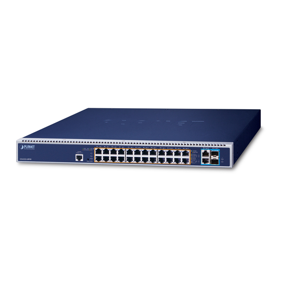
- Page 1 L3 24-Port 10/100/1000T 802.3bt + 2-Port 10GBASE-T + 2-Port 10G SFP+ Managed Switch with Dual Modular Power Supply Slots GS-6322 Switch Series Quick Installation Guide...
-
Page 2: Table Of Contents
Table of Contents 1. Package Contents ..................3 2. Requirements ..................... 4 2.1 Power Requirements ................4 3. Terminal Setup ................... 6 3.1 Logging on to Console ................. 7 3.2 Configuring IP Address ................. 8 4. Starting Web Management .................10 4.1 Logging in to the Managed PoE Switch ..........10 4.2 Saving Configuration via Web ..............12 5. Recovering Back to Default Configuration .............13 6. Power Operation Mode Management ............14... -
Page 3: Package Contents
1. Package Contents Thank you for purchasing PLANET L3 Multiple Gigabit + 4-Port 10G Managed Switch with dual modular power supply slots. The description of this model is shown below: 10G 10G Model Name PoE Ports PoE Budget RJ45 SFP+ Depended on power GS-6322-24P4X 24-Port 802.3bt supply “Managed PoE Switch” is used as an alternative name in this Quick Installation Guide. -
Page 4: Requirements
2. Requirements z Workstations running Windows 10/XP/2003/Vista/7/8/2008, MAC OS X or later, Linux, UNIX, or other platforms are compatible with TCP/IP protocols. z Serial Port Connection (Terminal) The above Workstations come with RS232 COM Port (DB9) or USB-to-RS232 converter. The above Workstations have been installed with terminal emulator, such as Hyper Terminal included in Windows XP/2003. Serial cable -- one end is attached to the RS232 serial port, while the other end to the console port of the Managed PoE Switch. - Page 5 For compatibility with electrical voltages in most areas of the world, the Managed PoE Switch’s modular power supply can automatically adjust line power in the range of 100-240V AC and 50/60 Hz. However, if you’d like to have maximum power output, it’s required specific power input. Plug the female C15 end of the power cord firmly into the receptacle on the rear panel of the Managed PoE Switch and the other end of the power cord into an electrical outlet and the power will be ready.
-
Page 6: Terminal Setup
3. Terminal Setup To configure the system, connect a serial cable to a RS232 COM port on a PC or notebook computer and to RJ45 type of serial port of the Managed PoE Switch. PC / Workstation with Terminal Emulation Software Managed Switch RS232 to RJ45 Cable Serial Port RJ45 Console Port Figure 3-1: Managed PoE Switch Console Connectivity A terminal program is required to make the software connection to the Managed PoE Switch. -
Page 7: Logging On To Console
3.1 Logging on to Console Once the terminal is connected to the device, power on the Managed PoE Switch, and the terminal will display “running testing procedures”. Then, the following message asks to log in user name and password. The factory default user name and password are shown as follows and the login screen in Figure 3-3 appears. -
Page 8: Configuring Ip Address
3.2 Configuring IP Address The Managed PoE Switch is shipped with default IP address shown below. IP Address: 192.168.0.100 Subnet Mask: 255.255.255.0 To check the current IP address or modify a new IP address for the Switch, please use the procedures as follows: Show the current IP Address 1. At the “#” prompt, enter “show ip interface brief”. 2. The screen displays the current IP address as shown in Figure 3-4. Figure 3-4: IP Information Screen Configuring IP Address 3. At the “#” prompt, enter the following command and press <Enter> as shown in Figure 3-5. - Page 9 The previous command would apply the following settings for the Managed PoE Switch. IP Address: 192.168.1.100 Subnet Mask: 255.255.255.0 Figure 3-5: Configuring IP Address Screen 4. Repeat step 1 to check if the IP address has changed. Store current switch configuration 5. At the “#” prompt, enter the following command and press <Enter>. # copy running-config startup-config Figure 3-6: Saving Current Configuration Command Screen If the IP is successfully configured, the Managed PoE Switch will apply the new IP address setting immediately. You can access the Web interface of the Managed PoE Switch through the new IP address.
-
Page 10: Starting Web Management
4. Starting Web Management The following shows how to start up the Web Management of the Managed PoE Switch. Note the Managed PoE Switch is configured through an Ethernet connection. Please make sure the manager PC must be set to the same IP subnet address. - Page 11 3. After entering the password, the main screen appears as Figure 4-3 shows. Figure 4-3: Web Main Screen of Managed PoE Switch 4. The Switch Menu on the top of the Web page lets you access all the commands and statistics the Industrial Managed Switch provides. The Switch Menu always contains one or more buttons, such as “System”, “Switching”, “Routing”, “QoS”, “Security”, “PoE”, “Ring”, “ONVIF” and “Maintenance”.
-
Page 12: Saving Configuration Via Web
4.2 Saving Configuration via Web To save all applied changes and set the current configuration as a startup configuration, the startup-configuration file will be loaded automatically across a system reboot. 1. Click the Save icon on the top Switch Menu bar. 2. Press the “Save Configuration” button. 3. -
Page 13: Recovering Back To Default Configuration
5. Recovering Back to Default Configuration IP address has been changed or admin password has been forgotten – To reset the IP address to the default IP address “192.168.0.100” or reset the login password to default value, press the hardware-based reset button on the rear panel for about 10 seconds. After the device is rebooted, you can log in the management Web interface within the same subnet of 192.168.0.xx. -
Page 14: Power Operation Mode Management
6. Power Operation Mode Management The GS-6322-24P4X is designed with two extractive modular power supply slots to support Redundant Power Supply (RPS) mode or Extended Power Supply (EPS) mode via software setting to handle the demands of power redundancy or additional power to PoE++ ports as needed. - Page 15 Figure 6-2: Power Configuration web page Please refer to the user’s manual for more.
-
Page 16: Customer Support
7. Customer Support Thank you for purchasing PLANET products. You can browse our online FAQ resource and User’s Manual on PLANET Web site first to check if it could solve your issue. If you need more support information, please contact PLANET switch support team. PLANET online FAQs: https://www.planet.com.tw/en/support/faq Switch support team mail address: support@planet.com.tw GS-6322 Series User’s Manual: https://www.planet.com.tw/en/support/downloads?method=keyword&keyword= GS-6322 (Please select your switch model name from the drop-down menu of Product Model.) Copyright © PLANET Technology Corp. 2020. Contents are subject to revision without prior notice.
Need help?
Do you have a question about the GS-6322 Series and is the answer not in the manual?
Questions and answers