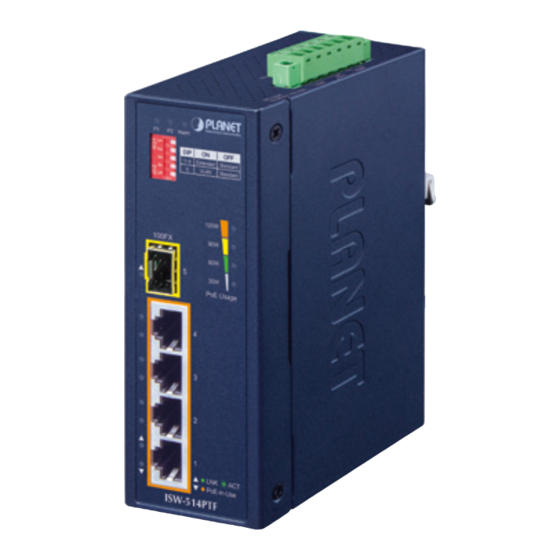
Summary of Contents for Planet Networking & Communication ISW-504PT
- Page 1 Industrial 5-Port Ethernet Switch with 4-Port PoE+ ISW-504PT/ISW-514PTF User’s Manual...
-
Page 2: Table Of Contents
Table of Contents 1. Package Contents ................. 3 2. Hardware Introduction ................4 2.1 Switch Front Panel ................. 4 2.2 LED Indicators ................6 2.3 Switch Upper Panel ................ 7 2.4 Wiring the Power Inputs ..............7 2.5 Wiring the Fault Alarm Contact ............9 2.6 Grounding the Device .............. -
Page 3: Package Contents
1. Package Contents Thank you for purchasing PLANET 5-Port Industrial Ethernet Switch with 4-Port PoE+, ISW-504PT/ISW-514PTF. The interfaces of these models are shown below: Model Name 10/100Mbps RJ45 Ports 100FX SFP Slots PoE+ Ports ISW-504PT ISW-514PTF In the following section, the term “Industrial PoE+ Switch” means the ISW-504PT/ISW-514PTF. -
Page 4: Hardware Introduction
PoE Usage PoE-in-Use PoE-in-Use ISW-504PT ISW-514PTF Figure 2-1: ISW-504PT front panel Figure 2-2: ISW-514PTF front panel 1. Fast Ethernet TP Interfaces 10/100BASE-TX copper, RJ45 twisted-pair: Up to 100 meters. 2. 100BASE-FX SFP Slot (ISW-514PTF) 100BASE-FX mini-GBIC slot, SFP (Small Factor Pluggable) transceiver module: From 2 kilometers (multi-mode fiber) to 20/40/60/120 kilometers (single-mode fiber). - Page 5 3. DIP Switch The Industrial PoE+ Switch provides one DIP switch for Standard, VLAN and Extended mode selections. The detailed descriptions are shown in the following table. DIP Switch Mode Function Standard Switches 1 to 5 are off This mode makes the Industrial PoE+ Switch operate as a general switch and all PoE ports operate at 10/100Mbps auto-negotiation.
-
Page 6: Led Indicators
Lights: indicates the port is providing DC in-line power. PoE - Amber Off: indicates the connected device is not a PoE powered in-Use device (PD). Per 10/100BASE-TX Interface (Port 5 of ISW-504PT) Color Function Lights: indicates the link through that port is successfully LNK/ established at 10/100Mbps. -
Page 7: Switch Upper Panel
Per 100FX SFP Slot (Port 5 of ISW-514PTF) Color Function Lights: indicates the link through that port is successfully LNK/ established at 100Mbps. Green Blinks: indicates that the switch is actively sending or receiving data over that port. 2.3 Switch Upper Panel The upper panel of the Industrial PoE+ Switch consists of one terminal block connector within two DC power inputs. - Page 8 1. Insert positive and negative DC power wires into contacts 1 and 2 for POWER 1, or 5 and 6 for POWER 2. Max. Fault Alarm Loading: 24V, 1A 1 2 3 4 5 6 DC Input: 12-54V , 7A max. PWR1 Alarm PWR2...
-
Page 9: Wiring The Fault Alarm Contact
2.5 Wiring the Fault Alarm Contact The fault alarm contacts are in the middle of the terminal block connector as the picture shows below. Inserting the wires, the Industrial PoE+ Switch will detect the fault status of the power failure and then forms an open circuit. The following illustration shows an application example for wiring the fault alarm contacts. -
Page 10: Grounding The Device
2.6 Grounding the Device Users MUST complete grounding wired with the device; otherwise, a sudden lightning could cause fatal damage to the device. Max. Fault Alarm Loading: 24V, 1A 1 2 3 4 5 6 DC Input: 12-54V , 7A max. PWR1 Alarm PWR2... -
Page 11: Installation
DIN-rail and wall. Basic knowledge of networking is assumed. Please read this chapter completely before continuing. The installation procedures of the ISW-504PT and ISW-514PTF are the same as they are shown below. 3.1 DIN-rail Mounting Installation... -
Page 12: Wall-Mount Plate Mounting
3.2 Wall-mount Plate Mounting 3.3 Side Wall-mount Plate Mounting You must use the screws supplied with the wall-mounting brackets. Damage caused to the parts by using incorrect screws would invalidate your warranty. -
Page 13: Troubleshooting
4. Troubleshooting This chapter contains information to help you solve issues. If the Industrial PoE+ Switch is not functioning properly, make sure the Industrial PoE+ Switch was set up according to instructions in this manual. The per port LED is not lit Solution: Check the cable connection of the Industrial PoE+ Switch. -
Page 14: Customer Support
5. Customer Support Thank you for purchasing PLANET products. You can browse our online FAQ resource at the PLANET Web site first to check if it could solve your issue. If you need more support information, please contact PLANET support team. PLANET online FAQs: https://www.planet.com.tw/en/support/faq Support:team mail address...


Need help?
Do you have a question about the ISW-504PT and is the answer not in the manual?
Questions and answers