
Summary of Contents for Pacific UPC-32
- Page 1 UPC-32 / UPC-12 PROGRAMMABLE CONTROLLERS FIRMWARE V2.53 AND LATER OPERATION MANUAL PACIFIC δ POWER SOURCE...
- Page 3 CONTROLLER, MODEL: S/N: POWER SOURCE, MODEL: S/N: THE INFORMATION CONTAINED IN THIS MANUAL IS PROPRIETARY TO PACIFIC POWER SOURCE, INC. AND MAY NOT BE COPIED OR REPRINTED WITHOUT ITS EXPRESSED WRITTEN CONSENT. PACIFIC POWER SOURCE, INC. 17692 Fitch Irvine, CALIF. 92614 THIRD EDITION COPYRIGHT (C) PPSI MARCH, 2004.
- Page 4 WAS SHIPPED FROM THE FACTORY. LIMITED WARRANTY Pacific Power Source (PPS) warrants each unit to be free from defects in material and workmanship. For the period of two (2) years from the date of shipment to the purchaser, PPS will either repair or replace, at its sole discretion, any unit returned to its factory in Irvine, California.
-
Page 5: Table Of Contents
SECTION 1 GENERAL TABLE OF CONTENTS PAGE HOW TO... FRONT PANEL REFERENCE ........ vi REMOTE INTERFACE FUNCTION REFERENCE......vii GENERAL ............. 1 USING THIS MANUAL......... 1 SAFETY NOTICES ........... 1 GENERAL PRODUCT DESCRIPTION ......3 1.3.1 UPC DESCRIPTION ........3 1.3.2 CONTROLLER MODELS ........ - Page 6 SECTION 1 GENERAL TABLE OF CONTENTS PAGE INSTALLATION ..........22 REMOVE INPUT SERVICE ........23 REMOVE COVER AND CABLING ....... 23 REMOVE EXISTING CONTROLLER ......23 CONFIGURE UPC ........... 23 3.4.1 CONFIGURE TRANSFORMER RATIO ......24 3.4.2 CONFIGURE AMPS TO VOLTS RATIO ......25 3.4.3 CONFIGURE GPIB DEVICE ADDRESS ......
- Page 7 SECTION 1 GENERAL TABLE OF CONTENTS PAGE GPIB and REMOTE OPERATION ........77 INTRODUCTION ..........77 CONVENTIONS..........78 PROGRAM CONTROL ........80 5.3.1 STEADY-STATE OUTPUT PARAMETERS ..... 81 5.3.2 TRANSIENT SEGMENT PARAMETERS ....... 82 5.3.3 PROGRAM MEMORY CONTROL ......83 SIGNAL CONTROL ..........
- Page 8 SECTION 1 GENERAL TABLE OF CONTENTS PAGE CALIBRATION ..........107 CALIBRATION INTERVAL........107 8.1.1 TEST EQUIPMENT REQUIREMENTS ......107 MANUAL CALIBRATION PROCEDURE......107 8.2.1 OSCILLATOR GAIN CALIBRATION ......108 8.2.2 PROGRAMMABLE CURRENT LIMIT CALIBRATION..... 110 8.2.3 OUTPUT VOLTMETER CALIBRATION ....... 110 EXTERNALLY REFERENCED CALIBRATION .....
- Page 9 SECTION 1 GENERAL LIST OF ILLUSTRATIONS FIGURE 1.3 SCU/UPC-32, SCU/UPC-12.................... 5 FIGURE 2.3.3 J3 CONTROL AND OSCILLATOR................17 FIGURE 2.3.6 J5 AUXILIARY INPUTS AND OUTPUTS ..............19 FIGURE 2.3.8 J2 METERING INPUTS....................20 FIGURE 2.4 J4 GPIB REMOTE INTERFACE ................... 21 FIGURE 3.4.1...
-
Page 10: How To
SECTION 1 GENERAL HOW TO... FRONT PANEL REFERENCE This is a quick reference to commonly used FRONT PANEL functions and will aid the user in quickly learning how to use functions of interest. HOW TO SECTION CALIBRATE METERS CALIBRATE PROGRAMMABLE OUTPUT IMPEDANCE 4.6.3.1.1 CHANGE OPERATING MODES 4.1.1... -
Page 11: Remote Interface Function Reference
SECTION 1 GENERAL REMOTE INTERFACE FUNCTION REFERENCE This is a quick reference to commonly used REMOTE INTERFACE functions and will aid the user in quickly finding the functions of interest. FUNCTION SECTION CALIBRATE METERING CALIBRATE PROGRAMMABLE OUTPUT IMPEDANCE 5.4.1 CLOSE / OPEN OUTPUT CONTACTOR 5.7.5 CREATE A PROGRAM 5.3, 5.7.1... - Page 12 SECTION 1 GENERAL THIS PAGE INTENTIONALLY BLANK viii...
-
Page 13: General
This manual is to be used with either the UPC32 or UPC12 controller. These may be installed in the SCU (System Control Unit), or directly into one of Pacific Power Source’s AMX or ASX models. USING THIS MANUAL It is very important that the user reads SECTION 4 (Front Panel Operation) prior to using this equipment. - Page 14 SECTION 1 GENERAL SAFETY NOTICES (cont) WARNING THIS EQUIPMENT CONTAINS HIGH ENERGY, LOW IMPEDANCE CIRCUITS!! LETHAL POTENTIALS ARE CONTAINED WITHIN THE CABINET. CARE MUST BE EXERCISED WHEN SERVICING THIS EQUIPMENT IN ORDER TO PREVENT SERIOUS OPERATOR INJURY OR EQUIPMENT DAMAGE. VOLTAGE AT THE TERMINALS RESPONDS INSTANTLY WHEN THE OUTPUT IS ACTIVATED.
-
Page 15: General Product Description
Pacific Power Source's AMX/ASX Series Power Sources or into a System Control Unit for use with other power sources. The UPC is designed for use with any of Pacific Power Source, Inc.’s AC Power Sources and is interchangeable with other UPC/UMC Series controllers. - Page 16 GENERAL 1.3.1 UPC DESCRIPTION (cont’d) The signal generation section produces one (UPC-12) or three (UPC-32) output signals representing the output phase waveforms of the power source. The UPC controllers produce steady-state signals - a base set of volts, frequency, waveforms and phase angle - and dynamic signals in which parameters change with time.
-
Page 17: Figure 1.3 Scu/Upc-32, Scu/Upc-12
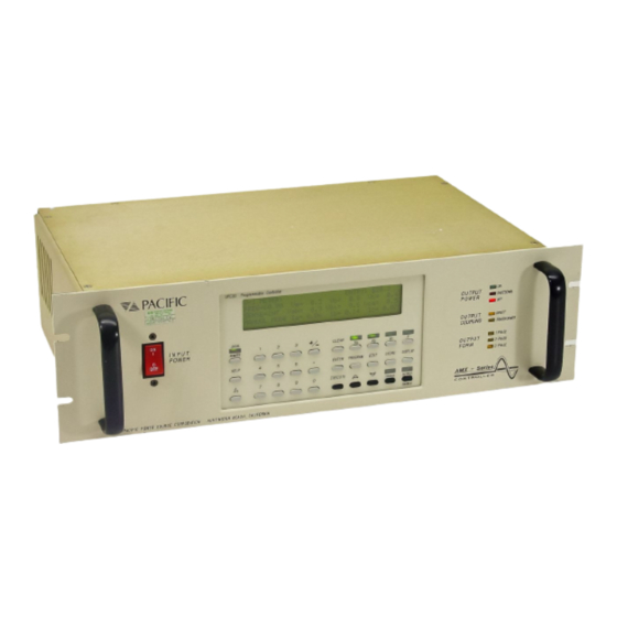
SECTION 1 GENERAL PA CIFIC Figure 1.3a SCU/UPC-32 Figure 1.3b UPC-32 Figure 1.3c UPC-12... -
Page 18: Controller Models
The complete designation for a "stand-alone" controller housing a UPC- 32 is SCU/UPC-32. Such a unit can drive some of the larger PACIFIC AMX or ASX power sources through their rear panel interface. A typical usage might be to locate the power source at the base of an instrument rack, with the controller installed in an upper slot at a more convenient eye level or even in a completely different location. -
Page 19: Specifications
SPECIFICATIONS SECTION 2 SPECIFICATIONS SPECIFICATIONS This section states the specifications of both Output Control and Metering capabilities of the UPC. The UPC-32 is assembly number: 133600. The UPC-12 is assembly number: 133700. Ambient operating conditions are as follows. Temperature 0-50ºC. -
Page 20: Voltage Control Specifications
SECTION 2 SPECIFICATIONS 2.1.2 VOLTAGE CONTROL SPECIFICATIONS The voltage amplitude of each vector can be varied independently. There are two output coupling modes selectable in the stored programs of the UPC. 1) DIRECT COUPLED MODE: Range: 0 to 150 VAC rms Resolution: 0.1 volts Output Ratio:... -
Page 21: Current Limit Control Specifications
SECTION 2 SPECIFICATIONS 2.1.2.1 CSC (CONTINUOUS SELF CALIBRATION) SPECIFICATIONS The UPC includes a user selectable “Continuous Self Calibration” function. When active, this function maintains a constant output voltage amplitude at the metering sense point, comparing the metered voltage at that point to the set value and correcting for any difference. Accurate calibration of the voltage metering function is essential for CSC to operate accurately. -
Page 22: Waveform Control Specifications
SECTION 2 SPECIFICATIONS 2.1.4 WAVEFORM CONTROL SPECIFICATIONS The standard hardware configuration supports 16 waveforms with an option to store 128. There are 16 pre-stored waveforms in the UPC EPROM which are available to initialize the 16 waveforms stored in RAM. Each output phase is generated by one of the 16 waveforms stored in RAM. Waveform 1 is always a Sine wave and cannot be changed. - Page 23 SECTION 2 SPECIFICATIONS The previously listed waveforms are created using this Waveform formula: Σ α sin(nwτ + δ) WAVEFORM = Where: n = harmonic number α = harmonic amplitude (% of fundamental) δ = harmonic phase angle As an example, the above formula may use values from the following tables: WAVEFORM #1 SINE WAVE α...
-
Page 24: Output Power Form Control Specifications
SPECIFICATIONS 2.1.5 OUTPUT POWER FORM CONTROL SPECIFICATIONS The UPC-32 can create single (one), split (two), or three phase waveforms with ΦB and ΦC at any phase angle referenced to phase A. The UPC-12 generates only one output vector. When used in an AMX or ASX Power Source, it may generate single (one) and split (two) phase output. -
Page 25: Metering Specifications
SECTION 2 SPECIFICATIONS METERING SPECIFICATIONS 2.2.1 VOLTMETER SPECIFICATIONS Three voltmeter inputs are provided, one per phase. Both Voltage Line-to-Neutral (VLN) and Voltage Line-to-Line (VLL) voltages are metered. Vrms Meter Range: 354 VLN, 708 VLL A.C. Display Resolution: 0.1 VAC rms. The Remote interface may provide up to 3 digits of precision (digits to the right of the decimal point). -
Page 26: Kilowatt Meter Specifications
SECTION 2 SPECIFICATIONS 2.2.4 KILOWATT METER SPECIFICATIONS True kilowatt metering is provided using the voltmeter and ammeter inputs. Display range and resolution is XXX.XXX kW. The Remote interface may provide 3 digits of precision (digits to the right of the decimal point). -
Page 27: Electrical Interface
SECTION 2 SPECIFICATIONS 2.2.7 WAVEFORM ANALYSIS (cont’d) The harmonic data is reported using a sine series with coefficients expressed in polar format (magnitude and phase angle). Each magnitude percentage is referenced to the fundamental which is always defined as having a magnitude of 100%. -
Page 28: Output Control
SECTION 2 SPECIFICATIONS 2.3.4 OUTPUT CONTROL Digital outputs are ± 15 VDC, positive logic. The UPC sends the following control signals to the power source on J3: NAME FUNCTION 3Φ - CMD 3Φ output form command 1Φ - CMD 1Φ output form command NOTE: If both 3Φ... -
Page 29: Figure 2.3.3 J3 Control And Oscillator
SECTION 2 SPECIFICATIONS (Rear of SCU) SPARE – CMD 3Φ – CMD 1Φ – CMD CONNECTOR – CMD EXT SENSE – CMD SPARE – CMD XFMR CPLD – CMD OUTPUT 0N – CMD LV COMMON SPARE – CONF SPARE – CONF CONNECTOR –... -
Page 30: Analog Inputs
SECTION 2 SPECIFICATIONS 2.3.6 ANALOG INPUTS Three Auxiliary Inputs are provided on J5, one per phase. The Auxiliary Inputs are AC coupled and algebraically summed to the Oscillator signals produced by the UPC. It should be noted that the Auxiliary Inputs can be used as external inputs simply by programming the UPC for 0 VAC output. Auxiliary Input voltage range (Vaux): ±... -
Page 31: Figure 2.3.6 J5 Auxiliary Inputs And Outputs
SECTION 2 SPECIFICATIONS (Rear of SCU) LV COMMON TRANSIENT TRIGGER LV COMMON TRANSIENT PEDESTAL LV COMMON LV COMMON SYNC OUT ΦA AM LO ΦA AM HI ΦB AM LO ΦB AM HI ΦC AM LO ΦC AM HI ΦA AUX IN LO ΦA AUX IN HI ΦB AUX IN LO ΦB AUX IN HI... -
Page 32: Metering Inputs
SECTION 2 SPECIFICATIONS 2.3.8 METERING INPUTS Metering inputs are on J2. Common mode must be within ± 10 V with respect to power supply peak common. (Rear of SCU) ΦA CURRENT HI ΦA CURRENT LO ΦB CURRENT HI ΦB CURRENT LO ΦC CURRENT HI ΦC CURRENT LO 1Φ... -
Page 33: Gpib Remote Interface
SECTION 2 SPECIFICATIONS GPIB REMOTE INTERFACE The GPIB Remote Interface is provided on J4. It has listener and talker capabilities. The GPIB device address is set via the UPC STATUS display screen. Default address is 1. See section 4.6.3.3 for configuration and section 5 for programming information. (Rear of SCU) DI 01 DI 05... -
Page 34: Installation
Refer to the power source manual for installation into a Pacific Power Source, Inc. power source system. Should a question arise, call Pacific Power Source, toll free, at 1-800-854-2433. -
Page 35: Remove Input Service
SECTION 3 INSTALLATION REMOVE INPUT SERVICE Turn the Input Power Circuit Breaker on the front panel OFF. Then disconnect the Input Line Cord from the rear of the SCU chassis. See figure 3.5. REMOVE COVER AND CABLING • Remove six screws from the top cover then remove the top cover. •... -
Page 36: Configure Transformer Ratio
SECTION 3 INSTALLATION 3.4.1 CONFIGURE TRANSFORMER RATIO NOTE: Most users will not need to concern themselves with the unit configuration as it is set at the factory if the UPC is packaged with a power source. Set the TRANSFORMER RATIO of the UPC to be the same as the turns ratio of the Output XFMR in the Power Source. -
Page 37: Configure Amps To Volts Ratio
SECTION 3 INSTALLATION 3.4.2 CONFIGURE AMPS TO VOLTS RATIO NOTE: Most users will not need to concern themselves with the following configuration issue as it is set at the factory if the UPC is packaged with a power source. The ammeter scale is selected by the AMPS TO VOLTS RATIO SWITCH multiplied by a factor of 10. The AMPS TO VOLTS RATIO scales the voltage fed into the ammeter circuit input to represent a given amount of current. -
Page 38: Configure Gpib Device Address
SECTION 3 INSTALLATION 3.4.3 CONFIGURE GPIB DEVICE ADDRESS Set the GPIB DEVICE ADDRESS as desired. The GPIB device address is set via the UPC STATUS display screen. Default address is 1. See paragraph 4.6.3.3 for configuration. NOTE: IEEE-488 type cables with 90º "cable to connector" bends may interfere with other interface connectors on the SCU and some power source model's rear panels. -
Page 39: Figure 3.4.1 Transformer And Amps To Volts Ratio Dip-Switch
SECTION 3 INSTALLATION ASSY No. 12345678 12345678 FIGURE 3.4.1 UPC METERING DIP SWITCHES TRANSFORMER RATIO AND AMPS-TO-VOLTS RATIO SWITCH LOCATION F. P. METER ØB+ C ASSY NO. IWA NO. SN NO. FIGURE 3.4.4 UPC INTERFACE DIP-SWITCH – CONFIGURATION SETTINGS... -
Page 40: Install Upc
SECTION 3 INSTALLATION INSTALL UPC NOTE: Most users will not need to concern themselves with the following installation issue if the UPC is packaged with a power source. Install the UPC with 2 nuts attaching the UPC front panel to the SCU front panel. See figure 3.5. Install LED PCB with 4 nuts, attaching the LED PCB to the SCU front panel. -
Page 41: Figure 3.5 Installation
SECTION 3 INSTALLATION ATTACH J5 TO ATTACH J4 TO REAR PANEL REAR PANEL CONNECT J6A TO P6A INTER- CONNECT FACE J2A HEADER TO P2A SOCKET OSC C OSC B OSC A METERING DISPLAY KEYBOARD CONNECT - 2 PLACES - 133071 P3A TO ATTACH CIRCUIT... -
Page 42: Front Panel Operation
This section describes the front panel operation of an UPC Controller installed in a power source. The UPC controllers are used with Pacific Power Source, Inc’s AMX, ASX, G, and MS series equipment. The UPC Controller allows the user to control all output parameters of the power source via the front panel keyboard as well as through the REMOTE interface (see Section 5 for REMOTE operation). - Page 43 SECTION 4 OPERATION 4.1.1 QUICK OVERVIEW (cont) The PROGRAM OPERATE mode attempts to simplify certain test operations by allowing the operator to execute pre-stored programs (combinations of Volts, Frequency, Output Coupling, Transformer tap selection if any, Phase angle, Waveform, and Current limit. A stored program can be executed simply by pressing PROGRAM, entering a program number, then EXECUTE.
- Page 44 SECTION 4 OPERATION 4.1.1 QUICK OVERVIEW (cont) SELECTING OPERATING MODES On first turn-on, the system will operate using a set of default parameters stored in memory. The display will be the V/I METER display. This is the default - and most frequently used - display. It shows all basic operating parameters, and in the lower left portion shows the operating mode.
-
Page 45: Quickly Putting The Unit To Use
SECTION 4 OPERATION 4.1.2 QUICKLY PUTTING THE UNIT TO USE The following steps provide a quick method (using MANUAL MODE) for setting Voltage and Frequency and applying power to a load. To set other parameters, such as phase angle, waveform, current limit, power form and output coupling mode (transformer or direct), use the PROGRAM EDIT MODE. -
Page 46: Figure 4.1 Power Source Front Panel
SECTION 4 OPERATION FIGURE 4.1 POWER SOURCE FRONT PANEL... -
Page 47: Front Panel Controls And Indicators
SECTION 4 OPERATION FRONT PANEL CONTROLS AND INDICATORS This section shows the locations and defines the functions of the front panel controls and indicators of the UPC as installed in an AMX/ASX Series power source. Operation of an UPC installed in an SCU is identical except the SCU has no Output Power Switch. -
Page 48: Upc Front Panel
SECTION 4 OPERATION 4.2.2 UPC FRONT PANEL LIQUID CRYSTAL Gives pertinent information to the user relating to front panel DISPLAY operation. (LCD) LOCAL / REMOTE When the REMOTE INTERFACE is in control of the UPC and has (KEY and LED) not issued a local lockout command, this key will return control to the keyboard. - Page 49 SECTION 4 OPERATION 4.2.2 UPC FRONT PANEL (cont’d) ENTER Is used to enter numeric values then move the cursor to the next (KEY) data field. PROGRAM When pressed from any meter display causes PROGRAM (KEY) OPERATE MODE to be active. EDIT When pressed from the PROGRAM display causes PROGRAM (KEY)
-
Page 50: Manual Mode
SECTION 4 OPERATION MANUAL MODE This section describes operation in Manual Mode. In this mode you may slew or directly enter voltage or frequency values. Parameters other than volts and frequency can only be changed by editing and executing a steady-state Program. The V/I METER display will indicate MANUAL MODE in the lower left corner of the display. - Page 51 SECTION 4 OPERATION 4.3.1 METERING DISPLAYS (cont) 4.3.1.1 WAVEFORM ANALYSIS (OPTION- Harmonic Analysis and Synthesis) Waveform analysis functions are optionally available to report both magnitude and phase angle (relative to 0º of the fundamental voltage waveform) of each harmonic for metered voltage and current waveforms.
- Page 52 SECTION 4 OPERATION 4.3.1.1 WAVEFORM ANALYSIS (cont’d) (OPTION- Harmonic Analysis and Synthesis) Pressing EDIT will allow the user to select the number of samples used during the analysis process. Select number of samples to analyze... ----> <nnn> The value of “nnn” may only be one of the numbers listed below. If any other number is entered, the default value of 128 will be used.
-
Page 53: Voltage Entry
SECTION 4 OPERATION 4.3.2 VOLTAGE ENTRY To achieve MANUAL MODE and change voltage, from any meter display light the Va, Vb, Vc LEDs by pressing those keys. Pressing an ARROW key causes selected voltages to slew up or down. Entering a number then pressing EXECUTE causes selected voltages to change to new values. -
Page 54: Program Execution
SECTION 4 OPERATION 4.4.1 PROGRAM EXECUTION To achieve Program Operate Mode, from any meter display press the PROGRAM key. This will cause the PROGRAM display to become active. The last-edited or currently-executing program will be displayed. You may enter a new program number then press ENTER to view it. PROGRAM: #1 FORM=3 COUPLING=DIRECT FREQ=60... - Page 55 SECTION 4 OPERATION 4.4.2 TRANSIENT EXECUTION (cont’d) The most direct method to create a transient program is as follows. 1. From the V/I meter, press PROGRAM, enter the program number, press ENTER. 2. Press EDIT. Change steady-state values if desired, pressing ENTER after each entry. 3.
- Page 56 SECTION 4 OPERATION 4.4.2.1 MIL-STD-704D TRANSIENT PROGRAMS (cont) OVER-VOLTAGE TRANSIENT (Program #100) The power source will produce the over-voltage transient excursion as defined by MIL-STD-704D (Paragraph 5.2.3.2.1). The power source must be configured for a voltage range of at least 180Vrms to perform this test.
- Page 57 SECTION 4 OPERATION 4.4.2.1 MIL-STD-704D TRANSIENT PROGRAMS (cont) OVER-FREQUENCY TRANSIENT (Program #102) The power source will produce the over-frequency transient excursion as defined by MIL-STD-704D (Paragraph 5.2.3.2.1). The power source must be configured for a voltage range of at least 115Vrms to perform this test.
- Page 58 SECTION 4 OPERATION 4.4.2.1 MIL-STD-704D TRANSIENT PROGRAMS (cont) UNDER-FREQUENCY TRANSIENT (Program #103) The power source will produce the under-frequency transient excursion as defined by MIL-STD-704D (Paragraph 5.2.3.2.1). The power source must be configured for a voltage range of at least 115Vrms to perform this test.
-
Page 59: Program Edit Mode
SECTION 4 OPERATION PROGRAM EDIT MODE This section describes the Program Edit Mode which allows program and transient definition and editing. 4.5.1 PROGRAM EDITING To start the Program Edit Mode, from any meter display press the PROGRAM key, program number, ENTER key then EDIT key. - Page 60 SECTION 4 OPERATION 4.5.1 PROGRAM EDITING (cont) FREQ: Any desired output frequency from 20.00 to 5000 Hz. may be entered. RANGE RESOLUTION 20.00 - 99.99 Hz 0.01 Hz 100.0 - 999.9 Hz 0.1 Hz 1000 – 5000 Va, Vb, Vc: Line to neutral voltages are entered for 1Φ and 3Φ Forms. Line to Line voltages are entered for 2Φ...
- Page 61 SECTION 4 OPERATION 4.5.1.1 PROGRAM EXAMPLE The following is an example of how to create and execute a 3 phase, 108/187 volt, 400 Hz program. From any metering display press the PROGRAM key. PROGRAM: #1 FORM=3 COUPLING=DIRECT FREQ=60 Va=120 Vb=120 Vc=120 WFa=1 WFb=1...
- Page 62 SECTION 4 OPERATION 4.5.1.1 PROGRAM EXAMPLE (cont) Press 108, ENTER, 108, ENTER, 108, ENTER, to select 108 volts line to neutral on all three phases. PROGRAM: #4 FORM=3 COUPLING=DIRECT FREQ=400 Va=108 Vb=108 Vc=108 WFa=1 WFb=1 WFc=1 #SEGS=0 Ilim=50 PHb=120º PHc=240º Press 1 ENTER 1 ENTER 1 ENTER to select WaveForm 1 on all three phases.
-
Page 63: Transient Editing
SECTION 4 OPERATION 4.5.2 TRANSIENT EDITING Before beginning to create a transient, the sequence of the voltage, frequency, and waveform changes should be fully defined. The UPC allows transient events to be defined in two ways: Time-based transients and Cycle-based transients. Transient event timing always begins at 0 degrees of ΦA (the rising 0 volt crossing), and will proceed based on defined Segments. - Page 64 SECTION 4 OPERATION 4.5.2 TRANSIENT EDITING (cont’d) The following may be programmed: SEGMENT #: Segments define each “event” of a transient. Each segment provides a linear transition in volts and/or frequency in the time indicated. Different waveforms may also be switched in during each segment. Normally don't enter a number here.
- Page 65 SECTION 4 OPERATION 4.5.2.1 TIME BASED TRANSIENT EXAMPLE The following is an example of how to create a MIL-STD-704D time-based transient. (See section 4.4.2 regarding pre-stored transients) Start with the previous program #4 example as shown in section 4.5.1. From any metering display press PROGRAM, 4, ENTER, EDIT, EDIT, and you should see the following display: TRANSIENT: PRGM #4 SEGMENT #1...
- Page 66 SECTION 4 OPERATION 4.5.2.1 TIME BASED TRANSIENT EXAMPLE (cont) Press 1, ENTER, 1, ENTER, 1, to select WaveForm 1 on all three phases. TRANSIENT: PRGM #4 SEGMENT #1 OF 1 T=0.0002 Va=80 Vb=80 Vc=80 F=400 WFa=1 WFb=1 WFc=1 Press ENTER, now we are starting segment 2 of 2. TRANSIENT: PRGM #4 SEGMENT #2 OF 2...
- Page 67 SECTION 4 OPERATION 4.5.2.1 TIME BASED TRANSIENT EXAMPLE (cont) Press 1, ENTER, 1, ENTER, 1, to select WaveForm 1 on all three phases. TRANSIENT: PRGM #4 SEGMENT #2 OF 2 T=0.01 Va=80 Vb=80 Vc=80 F=400 WFa=1 WFb=1 WFc=1 Press ENTER, now we are starting segment 3 of 3. TRANSIENT: PRGM #4 SEGMENT #3 OF 3...
- Page 68 SECTION 4 OPERATION 4.5.2.1 TIME BASED TRANSIENT EXAMPLE (cont) Press 1, ENTER, 1, ENTER, 1, to select WaveForm 1 on all three phases. TRANSIENT: PRGM #4 SEGMENT #3 OF 3 T=0.07 Va=108 Vb=108 Vc=108 F=400 WFa=1 WFb=1 WFc=1 Press STORE, to save the transient sequence. TRANSIENT EVENTS: ENTER # OF TRANSIENT EVENTS 1 0 FOR INFINITE OR 1-65535.
-
Page 69: Figure 4.5.2.1 Mil-Std-704D Undervoltage Transient
SECTION 4 OPERATION 4.5.2.2 CYCLE BASED TRANSIENT EXAMPLE The following is an example of how to create a cycle based transient. This example presumes the user has loaded the program information as described in the previous examples. Start with program #4 example as shown in section 4.5.1.1. From any metering display press PROGRAM, 4, ENTER, EDIT, EDIT, and you should see the following display: TRANSIENT: PRGM #4 SEGMENT #1... - Page 70 SECTION 4 OPERATION 4.5.2.2 CYCLE BASED TRANSIENT EXAMPLE (cont) Press 15, ENTER, 15, ENTER, 15, to select waveform #15 on all three phases. TRANSIENT: PRGM #4 SEGMENT #1 OF 1 T=1 CYCLE Va=122 Vb=122 Vc=122 F=400 WFa=15 WFb=15 WFc=15 Press STORE, to save the transient sequence. TRANSIENT EVENTS: ENTER # OF TRANSIENT EVENTS 1 0 FOR INFINITE OR 1-65535.
- Page 71 SECTION 4 OPERATION START OF TRANSIENT END OF TRANSIENT SEGMENT 1 SEGMENT SEGMENT 108 VAC MIN STEADY-STATE LIMIT TIME, MILLISECONDS FIGURE 4.5.2.1 TIME BASED TRANSIENT - MIL-STD-704D UNDERVOLTAGE TRANSIENT WAVEFORM #2 WAVEFORM #3 WAVEFORM #1 SEGMENT 1 USES WAVEFORM #15 CYCLE BASED TRANSIENT FIGURE 4.5.2.2 SPIKE TRANSIENT...
-
Page 72: Setup Mode
SECTION 4 OPERATION SETUP MODE SETUP MODE is used to: • Copy and Delete Programs • Copy, Edit, and Create Waveforms • Set Min. and Max. Voltage Limits • Set Min. and Max. Frequency Limits • Engage and Disengage CSC (Continuous Self Calibration) •... - Page 73 SECTION 4 OPERATION 4.6.1.1 COPY PROGRAM COPY PROGRAM is used to copy Program data. From any METER display (V/I, AMPS or POWER), press the fn key to enter SETUP MODE. From the SETUP display, press 1 to enter PROGRAM SETUP. From the PROGRAM SETUP display, press 1 to enter COPY PROGRAM.
-
Page 74: Waveform Setup
SECTION 4 OPERATION 4.6.1.3 ERASE ALL RAM AND RESET CPU ERASE ALL RAM AND RESET CPU is used to erase edited programs 1-99 and edited waveforms 2-16. This will reset everything in the UPC including calibration values. Only do this if the UPC is acting abnormally or to restore all default settings. - Page 75 SECTION 4 OPERATION 4.6.2.1 EDIT WAVEFORM EDIT WAVEFORM is used to change or modify waveforms. From any METER display (V/I, AMPS or POWER), press the fn key to enter SETUP MODE. From the SETUP display, press 2 to enter WAVEFORM SETUP. From the WAVEFORM SETUP display, press 1 to enter EDIT WAVEFORM.
- Page 76 SECTION 4 OPERATION 4.6.2.1 EDIT WAVEFORM (cont) Press 2, ENTER, to select waveform 2. EDIT WAVEFORM: NUMBER=2 RANGE=2-16 STARTING PHASE ANGLE =0 0-359.9º ENDING PHASE ANGLE 0-359.9º VOLTAGE IN PERCENT =100 (+/-)0-100% Press 85, ENTER, to select the start angle. EDIT WAVEFORM: NUMBER=2 RANGE=2-16 STARTING PHASE ANGLE =85...
-
Page 77: Figure 4.6.2.1 Edited Waveform
SECTION 4 OPERATION 100% 85° 95° 100% 0° FIGURE 4.6.2.1 EDITED WAVEFORM... - Page 78 SECTION 4 OPERATION 4.6.2.2 COPY WAVEFORM COPY WAVEFORM is used to copy waveforms (WF) from one waveform number to another. From any METER display (V/I, AMPS or POWER), press the fn key to enter SETUP MODE. From the SETUP display, press 2 to enter WAVEFORM SETUP. From the WAVEFORM SETUP display, press 2 to enter COPY WAVEFORM.
- Page 79 SECTION 4 OPERATION 4.6.2.3 WAVEFORM SYNTHESIS (Option: Harmonic Analysis and Synthesis) WAVEFORM SYNTHESIS creates waveforms by using a sine wave series defined by Harmonic Magnitude and Phase Angle coefficients expressed in polar format (magnitude and phase angle). Each magnitude percentage is referenced to the fundamental which is always defined as having a magnitude of 100%.
-
Page 80: General Setup
SECTION 4 OPERATION 4.6.3 GENERAL SETUP GENERAL SETUP is used for UPC SETUP, LCD SETUP, UPC STATUS and POWER SOURCE STATUS. From any METER display (V/I, AMPS or POWER), press the fn key to enter SETUP MODE. From the SETUP display, press 3 to enter GENERAL SETUP 1. GENERAL SETUP 1: 4 POWER SOURCE STATUS 1 UPC SETUP... - Page 81 SECTION 4 OPERATION 4.6.3.1 UPC SETUP (cont’d) PROG. Zo: Programmable Output Impedance (OPTION) - Press EDIT to access the PROG. Zo menu (para 4.6.3.1.1). This option is used to compensate for dynamic loss in the output circuit or to control the output impedance of the power source by responding in real time to changes in the output current.
- Page 82 SECTION 4 OPERATION 4.6.3.1.1 PROGRAMMABLE OUTPUT IMPEDANCE SETUP MENUS (cont) CAUTION USE THIS FUNCTION WITH CARE CARELESS OR IMPROPER USE OF THE PROGRAMMABLE OUTPUT IMPEDANCE FUNCTION MAY RESULT IN OVER-VOLTAGE OR UNDER-VOLTAGE BEING PRESENTED TO THE LOAD, AND MAY CAUSE DAMAGE TO THE LOAD. REACTIVE LOADS MAY CAUSE THE OUTPUT POWER TO BECOME UNSTABLE (OSCILLATE) AND MAY CAUSE DAMAGE TO THE LOAD IF EXCESSIVE NEGATIVE IMPEDANCE IS USED! 4.6.3.1.1.1 PROGRAMMABLE OUTPUT IMPEDANCE CALIBRATION MENU...
- Page 83 SECTION 4 OPERATION 4.6.3.1.1.1 PROGRAMMABLE OUTPUT IMPEDANCE CALIBRATION MENU (cont’d) Calibration values for Direct coupled operation may be established via the following procedure. 1. Turn CSC OFF. Disable PROG. Zo. Execute a program in Direct coupled mode. A. Establish the difference in output voltage between no-load and full-load voltage. B.
- Page 84 SECTION 4 OPERATION 4.6.3.3 UPC STATUS UPC STATUS indicates firmware version, GPIB or RS-232 SERIAL interface status, and DIP switch settings. It also allows the user to set the GPIB device address. See section 10 if the RS-232 SERIAL REMOTE INTERFACE is installed. The UPC SETUP menu is accessed from the General Setup menu (fn,3,1).
- Page 85 SECTION 4 OPERATION 4.6.3.3 UPC STATUS (cont’d) TRANSFORMER RATIO: Output Transformer Ratio: To change this see section 3.4.1 CONFIGURE TRANSFORMER RATIO. Pas= 1, 2, or 3. This is the number of power amplifiers in the Power Source. To change this value, refer to para. 3.4.4 CONFIGURE MISCELLANEOUS SETTINGS.
- Page 86 SECTION 4 OPERATION 4.6.3.5 RANGE CONTROL Some power source models support Range Control to achieve maximum efficiency by matching the internal power supply to the output voltage requirement. The UPC allows selection of Range Control parameters even when it is not supported by the attached power source. In this case the following screens have no effect.
- Page 87 SECTION 4 OPERATION 4.6.3.7 INITIAL VOLTAGE Selecting INITIAL VOLTAGE from the General Setup 2 menu (fn,3,7,1) allows you to specify the initial power up output voltage amplitude. INITIAL VOLTAGE SETUP: VOLTAGE=0 (Press +/- Key to Toggle Selection (Press ENTER or EXECUTE to Exit VOLTAGE=: 0 or LAST EXECUTED.
- Page 88 SECTION 4 OPERATION 4.6.3.9 TRANSIENT WFs Selecting TRANSIENT WFs from the General Setup 2 menu (fn,3,7,3) allows you to specify the voltage calculation method used during transients. TRANSIENT WAVEFORM CALCULATION SETUP: K-FACTOR CALC FOR AUTO RMS=ENABLED (Press +/- Key to Toggle Selection (Press ENTER or EXECUTE to Exit RMS=: ENABLED or DISABLED.
-
Page 89: Gpib And Remote Operation
SECTION 5 REMOTE OPERATION SECTION 5 GPIB and REMOTE OPERATION GPIB and SERIAL REMOTE OPERATION This section describes remote control functions of the UPC over the IEEE-488 BUS or RS-232 Serial Remote Interface. It is strongly recommended that the user read Section 4 (Front Panel Operation) to become familiar with the capabilities of the UPC. -
Page 90: Conventions
SECTION 5 REMOTE OPERATION CONVENTIONS COMMANDS are shown in the left hand column in BOLD, beginning with an asterisk ( * ) or colon ( : ) text with NO underline. Command DESCRIPTIONS appear in the right hand column. SCPI is "Standard Commands for Programmable Instruments -1992". Refer to the SCPI 1992 standard for more information. - Page 91 SECTION 5 REMOTE OPERATION CONVENTIONS (cont) Multiple data parameter names and values must be separated by commas. 'Multiple keyword' messages may be sent without duplicating the first level SCPI keyword (i.e., SOURce). e.g., :SOURce:VOLTage1,120; VOLTage2,120; VOLTage3,120. A keyword is a single word beginning with a colon (:). Program Messages MUST be terminated with a LINE FEED (0Ahex, 10dec) or END (EOI) signal.
-
Page 92: Program Control
SECTION 5 REMOTE OPERATION PROGRAM CONTROL :PROGram:NAME <nn> Command: selects program “nn” for executing, deleting or copying. nn = <0> to <99> Query: returns the program number last selected. :PROGram[:SELected]:DEFine <program> Command: defines the values stored in program “nn”. Both steady- state and transient segment parameter names and values may be sent. -
Page 93: Steady-State Output Parameters
SECTION 5 REMOTE OPERATION 5.3.1 STEADY-STATE OUTPUT PARAMETERS FORM,<n> sets Output Power Form of selected program. n = <1>Single Φ, <2>Split Φ, or <3>Three Φ COUPLing,<s> sets Output coupling of selected program. s = <DIRECT> or <XFMR> XFMRRATIO,<n.nn> sets Output XFMR ratio (n.nn:1) of selected program. n.nn = <0.01>... -
Page 94: Transient Segment Parameters
SECTION 5 REMOTE OPERATION 5.3.2 TRANSIENT SEGMENT PARAMETERS SEGment,<n> selects transient segment n of the presently selected program to be edited. n = <1> to <100> FSEG,<n> sets objective Frequency of selected segment. n = <:SOUR:FREQ:LIM:MIN> to <:SOUR:FREQ:LIM:MAX> Hz. VSEG,<n> sets objective voltage ΦA, ΦB, ΦC of selected segment. -
Page 95: Program Memory Control
SECTION 5 REMOTE OPERATION 5.3.3 PROGRAM MEMORY CONTROL :PROGram:[SELected:]DELete Command: (No query) deletes selected program. :PROGram:DELete:ALL Command: (No query) deletes all programs, saveforms, calibration data, and setup values, performs device RESET, loads Program #1 with *RST default values, executes MANUAL MODE with *RST values. Waveforms (1-16) are re-loaded from ROM. - Page 96 SECTION 5 REMOTE OPERATION 5.4.1 OUTPUT PARAMETERS (cont) :[SOURce:]FREQuency <n> sets Output Frequency. Range of n is <:SOUR:FREQ:LIM:MIN> to <:SOUR:FREQ:LIM:MAX> Hz. For convenience, another query for programmed Frequency is available via the :MEASure:FREQuency? command. The returned value is an indicator of the set value only as the UPC does not actually measure Frequency.
- Page 97 SECTION 5 REMOTE OPERATION 5.4.1 OUTPUT PARAMETERS (cont) :[SOURce:]IMPEDance:STATE <b> Enables or disables the optional Programmable Output Impedance function. b = <OFF>, <0> or <ON>, <1> :[SOURce:]IMPEDance <z> Sets the value of the optional Programmable Output Impedance. z = varies based on the present configuration and operational mode of the power source.
-
Page 98: Signal Routing
SECTION 5 REMOTE OPERATION 5.4.2 SIGNAL ROUTING :[SOURce:]FORM <n> Sets Output power form. n = <1>Single Φ, <2>Split Φ, or <3>Three Φ :[SOURce:]COUPLing <s> Sets Output coupling. s = <DIRECT> or <XFMR> :[SOURce:]VOLTage:ALC[:STATE] <b> The ALC keyword controls CSC enable/disable. b = <OFF>... -
Page 99: Query Functions
SECTION 5 REMOTE OPERATION QUERY FUNCTIONS The following are 'query only' functions sent to the UPC through the communication bus. 5.5.1 CONFIGURATION QUERIES These query parameters are set via DIP switches within the UPC, not via bus communication. The values are specific to the hardware configuration of the individual power source. :[SOURce]:XFMRRATIO? Query: Output XFMR ratio. - Page 100 SECTION 5 REMOTE OPERATION 5.5.2 METERED DATA QUERIES (cont) :MEASure:FREQuency? Query: for programmed Frequency. The returned value is only an indicator of the programmed Frequency as the UPC does not actually measure Frequency. Returns <20.00> to <5000> Hz :MEASure:CURRent[:RMS]1? Query: metered RMS current ΦA. Returns <0>...
- Page 101 SECTION 5 REMOTE OPERATION 5.5.2 METERED DATA QUERIES (cont) :MEASure:PF1? Query: metered power factor (KW/KVA) ΦA. Returns <0> to <1.0> :MEASure:PF2? Query: metered power factor (KW/KVA) ΦB. Returns <0> to <1.0> :MEASure:PF3? Query: metered power factor (KW/KVA) ΦC. Returns <0> to <1.0> :FETCh[:WAVEform]:VOLT1? :FETCh[:WAVEform]:CURRent1? Query: metered waveform data (line-to-neutral voltage only).
-
Page 102: Event And Status Reporting
SECTION 5 REMOTE OPERATION 5.5.3 EVENT and STATUS REPORTING Events and device Status may be queried by the Bus Controller through the following registers and queues. Query commands are explicitly shown in this section for clarity. NOTE: It is recommended that reading EVENT and STATUS registers and queues occur in the following order. -
Page 103: Figure 5.1 Status Byte Model
SECTION 5 REMOTE OPERATION QUEUE READ BY NOT-EMPTY ADDRESSIN G UPC AS A TALKER OUTPUT QUEUE RESERVED SHUTDOWN READ BY SERIAL POLL SERVICE STATUS BYTE REQUEST REGISTER GENERATION READ BY *STB? & & & & & & & SERVICE REQUEST ENABLE REGISTER *SRE <NRf>... -
Page 104: Figure 5.2 Standard Event Register Model
SECTION 5 REMOTE OPERATION 5.5.3.1 IEEE-488.2 STATUS REPORTING (cont) STANDARD EVENT STATUS REGISTER (ESR) Events reported by the STANDARD EVENT STATUS register may be queried via the *ESR? command. Reading the ESR register clears it. The EVENT STATUS summary bit in the STATUS BYTE (STB) will be set when an unmasked EVENT STATUS bit goes true. - Page 105 SECTION 5 REMOTE OPERATION 5.5.3.1 IEEE-488.2 STATUS REPORTING (cont) IEEE-488.2 STATUS REPORTING COMMANDS NAME DEFINITION *IDN? Device Identification query. Returns <PPSC,UPC-MM,vN.NN,1338XX> where MM is the model number (12 or 32), N.NN is the firmware version number XX is the firmware assembly indicating installed options *CLS Clears the ESR and the STB registers as well as the SCPI :EVENt registers and ERROR/EVENT queue...
- Page 106 SECTION 5 REMOTE OPERATION 5.5.3.2 SCPI STATUS REPORTING (cont) • The STATus:OPERation and STATus:QUEStionable registers provide information about the present mode of operation. • Transition of a CONDition bit to the true state causes the EVENt bit to be set true. •...
-
Page 107: Figure 5.3 Scpi Status Registers Model
SECTION 5 REMOTE OPERATION ERROR/EVENT QUEUE Queue To EEQ bit of Not Empty STATUS BYTE (bit 2) [SYSTem:ERRor?] FED INTO OUTPUT QUEUE QUEStionable status (enabled events) VOLTage CURRent TIME POWer TEMPerature Logical OR FREQuency PHASe To SQS bit of MODulation STATUS BYTE CALibration (bit 3) -
Page 108: Device Control
SECTION 5 REMOTE OPERATION DEVICE CONTROL :SYSTem:BEEPer Command: sounds the front panel beeper once. No query. :SYSTem:KLOCK <b> Command: sets the keyboard lock enable state (para. 4.6.3.8). b = .<1> enables keyboard lock; <0> disables keyboard lock. Query: returns present lock enable state. :CALibrate:ZERO Command: resets all Metering correction factors. -
Page 109: Ieee-488.1 Interface Functions
SECTION 5 REMOTE OPERATION 5.6.1 IEEE-488.1 INTERFACE FUNCTIONS The following lists the IEEE-488.1 capabilities of the UPC. Refer to the ANSI/IEEE-488.1 1987 standard for more information. FUNCTION MNEMONIC REMOTE MESSAGE RECEIVED / Description Source handshake functions Acceptor handshake functions MTAnn - Talker subset 6. nn is GPIB device address 0-30 MLAnn - Listener subset 3. -
Page 110: Ieee-488.2 Device Control Commands
SECTION 5 REMOTE OPERATION 5.6.2 IEEE-488.2 DEVICE CONTROL COMMANDS The following lists the IEEE-488.2 Common Commands for Device Control of the UPC. Refer to the ANSI/IEEE-488.2 1987 standard for more information. *RST Command: RESET. Initialize the UPC with the following parameters: CURRENT LIMIT CURRENT METERING RANGE INITIAL VOLTAGE... -
Page 111: Remote Control Examples
SECTION 5 REMOTE OPERATION REMOTE CONTROL EXAMPLES The REN (remote enable) line on the bus interface must be kept true to maintain REMOTE CONTROL. REMOTE CONTROL can only be initiated while the UPC is displaying a Metering display or while in the UPC STATUS display, not while editing. -
Page 112: Example Of Storing A Program
SECTION 5 REMOTE OPERATION 5.7.1 EXAMPLE OF STORING A PROGRAM Step A. Address the UPC as a listener. :PROGram:NAME 1 <eos> Step B. Select Program 1. NOTE: <eos> is a LINE FEED (0Ahex, 10dec). Step C. Define program 1. Program 1 consists of steady-state and optional transient segment parameter names and values. -
Page 113: Example Of Program Query
SECTION 5 REMOTE OPERATION 5.7.2 EXAMPLE OF PROGRAM QUERY Step A. Address the UPC as a listener. :PROGram:NAME 1 <eos> Step B. Select Program 1. NOTE: <eos> is a LINE FEED (0Ahex, 10dec). :PROGram:DEFine? <eos> Step C. Query Program 1. Program 1 consists of steady-state and optional transient segment parameter names and values. -
Page 114: Example Of Executing A Stored Program
SECTION 5 REMOTE OPERATION 5.7.3 EXAMPLE OF EXECUTING A STORED PROGRAM Step A. Address the UPC as a listener. :PROGram:NAME 1 <eos> Step B. Select Program 1. NOTE: <eos> is a LINE FEED (0Ahex, 10dec) :PROGram:EXECute <eos> Step C. Execute Program. Step D. -
Page 115: Example Of Voltage And Current Measurement Query
SECTION 5 REMOTE OPERATION 5.7.6 EXAMPLE OF VOLTAGE and CURRENT MEASUREMENT QUERY How to query the UPC for three phase RMS volts (Line to Neutral) and RMS current metered values. LINE to LINE volts, KVA, KW, Power Factor, CURRENT Crest Factor, and Peak Current may also be queried in the same way. -
Page 116: Examples Of Voltage And Current Waveform Query
SECTION 5 REMOTE OPERATION 5.7.7 EXAMPLES OF VOLTAGE and CURRENT WAVEFORM QUERY This is an example of how to query the UPC for metered waveform values for phase A voltage and current. Step A. Address the UPC as a listener. Step B. -
Page 117: Maintenance
SECTION 6 MAINTENANCE SECTION 6 MAINTENANCE MAINTENANCE No maintenance is required for the UPC controller. See the AMX, ASX, G, or MS series power source Operator’s Manual for proper maintenance of the power systems. -
Page 118: Service
SERVICE SERVICE There are no user serviceable components in the UPC assembly. Pacific Power Source maintains a staff of highly trained technicians which are able to assist with diagnosing abnormal operation of the UPC. If questions arise, call the factory at 1-800-854-2433 (8am to 5pm PST, California, U.S.A.). -
Page 119: Calibration
SECTION 8 CALIBRATION SECTION 8 CALIBRATION CALIBRATION This section describes two methods of calibration of a UPC. To fully calibrate the SYSTEM for output voltage, current limit and metering accuracy, it is necessary to perform both the MANUAL CALIBRATION and then the EXTERNALLY REFERENCED CALIBRATION. The first method (para 8.2.X) is a manual procedure requiring that the top cover of chassis be removed and adjustments made. -
Page 120: Oscillator Gain Calibration
SECTION 8 CALIBRATION MANUAL CALIBRATION PROCEDURE (cont’d) WARNING OBSERVE THE FOLLOWING WHEN CALIBRATION IS REQUIRED: 1) REMOVE ALL JEWELRY FROM ARMS AND NECK WHEN CALIBRATINGTHIS EQUIPMENT. THIS PREVENTS THE POSSIBILITY OF SHORT CIRCUIT THROUGH THE JEWELRY, CAUSING BURNS TO, OR ELECTROCUTION OF, THE OPERATOR. 2) WEAR SAFETY GLASSES WHEN CALIBRATING THIS EQUIPMENTTO PREVENT EYE INJURY DUE TO FLYING PARTICLESCAUSED BY ACCIDENTAL SHORT CIRCUIT CONDITIONS. -
Page 121: Figure 8.2 Gain Control Locations
SECTION 8 CALIBRATION IEEE-488 AUXILLARY (GPIB) CABLE CABLE J5 AUX I/O J4 IEEE-488 Φ C OSC. GAIN Φ B OSC. GAIN Φ A OSC. GAIN METER GAIN J2A METERING METERING CURRENT LIMIT ADJUST CABLE FIGURE 8.2 GAIN CONTROL LOCATIONS... -
Page 122: Programmable Current Limit Calibration
SECTION 8 CALIBRATION 8.2.2 PROGRAMMABLE CURRENT LIMIT CALIBRATION Connect the high current load to the output of the power source. Connect an Ammeter to the load wiring (Shunt type preferred). Program the UPC Voltage to drive a load at 60% of rated output current of the power source @ 60 Hz. -
Page 123: Externally Referenced Calibration
SECTION 8 CALIBRATION EXTERNALLY REFERENCED CALIBRATION The UPC metering is designed to be easily calibrated in the field. Calibration may be required in order to ensure that the CSC function is able to precisely match the output voltage of the power source to the programmed command voltage. - Page 124 SECTION 8 CALIBRATION EXTERNALLY REFERENCED CALIBRATION (cont’d) WARNING OBSERVE THE FOLLOWING WHEN CALIBRATION IS REQUIRED: 1) REMOVE ALL JEWELRY FROM ARMS AND NECK WHEN CALIBRATINGTHIS EQUIPMENT. THIS PREVENTS THE POSSIBILITY OF SHORT CIRCUIT THROUGH THE JEWELRY, CAUSING BURNS TO, OR ELECTROCUTION OF, THE OPERATOR. 2) WEAR SAFETY GLASSES WHEN CALIBRATING THIS EQUIPMENTTO PREVENT EYE INJURY DUE TO FLYING PARTICLESCAUSED BY ACCIDENTAL SHORT CIRCUIT CONDITIONS.
- Page 125 Operate the power source in FORM 2 to calibrate Ia and Ib (single/split phase). UPC-32 a. Operate the power source in FORM 1 to calibrate I1 (single phase). b. Operate the power source in FORM 3 to calibrate Ia, Ib and Ic (three phase).
-
Page 126: K Factors Display
SECTION 8 CALIBRATION 8.3.1 K FACTORS DISPLAY The correction factors (kFactors) created during EXTERNALLY REFERENCED CALIBRATION may be displayed or modified directly, from the kFactors display screen. Activate the CALIBRATION Menu (fn, 4), press 3 and the kFactor display appears as shown below. Kin A:1.0000 B:1.0000 C:1.0000 Kex A:1.0000 B:1.0000 C:1.0000 A:1.0000 B:1.0000 C:1.0000 1P:1.0000... -
Page 127: User Diagnostics
SECTION 9 DIAGNOSTICS SECTION 9 USER DIAGNOSTICS USER DIAGNOSTICS This section is intended to aid the user in solving common problems that may occur while using the UPC. PROBLEM Incorrect or illogical operation, PROBABLE CAUSE – or program values invalid, Battery backed RAM information corrupt. - Page 128 SECTION 9 DIAGNOSTICS USER DIAGNOSTICS (cont’d) PROBLEM ERROR Message states PROBABLE CAUSE – RMS content of selected Waveform is not great enough to "ERROR - PROGRAMMED OUTPUT VOLTAGE produce programmed voltage, requiring more system gain VALUE EXCEEDS OUTPUT VOLTAGE RANGE. than is available.
- Page 129 SECTION 9 DIAGNOSTICS USER DIAGNOSTICS (cont’d) PROBLEM KEYS do not respond at all. PROBABLE CAUSE – Keyboard is locked SUGGESTED CURE: Press fn and EDIT keys to unlock keyboard. Refer to section 4.6.3.8 PROBLEM UPC does not respond to the GPIB PROBABLE CAUSE –...
- Page 130 SECTION 9 DIAGNOSTICS USER DIAGNOSTICS (cont’d) PROBLEM UPC does not respond to the RS-232, PROBABLE CAUSES – or responds with a COMMAND ERROR message. Incorrect communication parameters, i.e., Serial baud rate, parity or number of data/start/stop bits. Handshaking signals may not be wired correctly SUGGESTED CURE: Verify parameter settings match that of host computer.
-
Page 131: Serial Remote Interface Option
SECTION 10 SERIAL REMOTE INTERFACE SECTION 10 RS-232 SERIAL REMOTE INTERFACE OPTION RS-232 SERIAL REMOTE INTERFACE OPTION This section describes using the optional RS-232 (Serial) REMOTE interface of the UPC. This section is intended to be used in conjunction with section 5 of this Operation Manual. 10.1 GENERAL The RS-232 REMOTE interface may replace the IEEE-488 (GPIB) interface as an option in the UPC. -
Page 132: Installation
SECTION 10 SERIAL REMOTE INTERFACE 10.3 INSTALLATION Installation of the RS-232 interface is generally performed at the factory. This involves removing the IEEE-488 interface PCB assembly and rear panel connector/cable and installing the RS-232 interface assembly and rear panel connector/cable. INTERFACE PCB DIP Switch S1-5 must be set to ON to indicate that the RS-232 interface has been installed. -
Page 133: Communication Monitoring Aid
SECTION 10 SERIAL REMOTE INTERFACE 10.5.1 COMMUNICATION MONITORING AID The UPC STATUS Display (fn,3,3) displays "LISTENER" while data is being received from the HOST, or "TALKER" if a Query response (Message Available) is available and has not yet been completely sent by the UPC. -
Page 134: Physical Connections
SECTION 10 SERIAL REMOTE INTERFACE 10.6 PHYSICAL CONNECTIONS Connection to the UPC RS-232 interface is made via a DB-25 connector on the rear panel of the UPC SCU or POWER SOURCE. This connector replaces the GPIB (IEEE-488) connector. UPC Pinouts: (For connection to IBM-PC type DB-25) PIN 1 CHASSIS GROUND... -
Page 135: Testing The Rs-232 Remote Interface
SECTION 10 SERIAL REMOTE INTERFACE 10.7 TESTING THE RS-232 REMOTE INTERFACE Connect the UPC RS-232 serial interface to a DTE serial port of a PC using a DB-25 cable. Most 25 pin connectors on PC's are DTE type. The UPC is a DCE type and must connect to a DTE port. -
Page 136: Index
INDEX INDEX accuracy Section 2, 40,107 damage 1-3, 28, 70 ALC 86 data 72, 77, 79, 83, 86-89, 92, 96, 103, ambient 7 104, 117, 119, 121-123 amplitude data buffer 79, 97 harmonics 10 DDE 92 modulation (AM) 3,18 delete 61, 83 voltage 7,48,51,63,66,76 device 83, 90, 2, 93, 96-98, 121 diagnostic 73, 115-118... - Page 137 INDEX handshake 97, 118, 119 maintenance 2, 105 harmonic 11 MANUAL MODE 30, 33, 36-38, 41, 56, analysis 14, 15, 39, 40, 86, 89 58, 61, 74, 79, 83 synthesis 12, 67 MAV 90 help 36 MEASure 84, 87-89, 104 message 78-80, 83, 90, 97, 102, 104, IDN 93, 123 116, 121...
- Page 138 INDEX temperature 7, 71 query 78, 79, 87-90, 92-94, 101, 103, 104, terminator, <eos> 117, 119, 120 121, 123 test 107, 123 questionable event 90, 94 THD 10, 11, 14, 39, 89 queue 90, 93 TIME, segment 51, 52, 82 QYE 92 transformer 4, 8, 16, 24, 35, 47, 48, 52, Remote 6, 36, 97, 98...
-
Page 139: Notes
NOTES NOTES... -
Page 140: Modifications
MODIFICATIONS MODIFICATIONS MODIFICATIONS This section is reserved for any modifications that may be made.
Need help?
Do you have a question about the UPC-32 and is the answer not in the manual?
Questions and answers