
Related Manuals for Omron NXEIP202


Summary of Contents for Omron NXEIP202
- Page 1 Machine Automation Controller NX-series EtherNet/IP Coupler Unit User’s Manual NX-EIC202 EtherNet/IP Coupler Unit W536-E1-09...
- Page 2 No patent liability is assumed with respect to the use of the information contained herein. Moreover, because OMRON is constantly striving to improve its high-quality products, the information contained in this manual is subject to change without notice. Every precaution has been taken in the preparation of this manual. Neverthe- less, OMRON assumes no responsibility for errors or omissions.
-
Page 3: Introduction
Introduction Introduction Thank you for purchasing an NX-series EtherNet/IP Coupler Unit. This manual contains information that is necessary to use the NX-series EtherNet/IP Coupler Unit. Please read this manual and make sure you understand the functionality and performance of the NX-series EtherNet/IP Coupler Unit before you attempt to use it in a control system. -
Page 4: Table Of Contents
CONTENTS CONTENTS Introduction ......................1 Intended Audience ............................1 Applicable Products ............................. 1 CONTENTS........................ 2 Relevant Manuals ..................... 8 Manual Structure ...................... 9 Page Structure and Icons ..........................9 Special Information ............................ 10 Precaution on Terminology ........................10 Terms and Conditions Agreement ................ 13 Warranty, Limitations of Liability ........................ -
Page 5: Contents
CONTENTS Section 2 Features and System Configuration Features of EtherNet/IP Slave Terminals................2-2 System Configurations of EtherNet/IP Slave Terminals ............ 2-5 2-2-1 System Configuration ......................... 2-5 2-2-2 Types of NX Units ........................2-7 2-2-3 Safety Control System ........................ 2-8 Support Software........................2-9 2-3-1 Applicable Support Software ...................... - Page 6 CONTENTS Section 6 Installation Installing Units........................6-2 6-1-1 Installation Precautions ....................... 6-2 6-1-2 Preparations for Installation ......................6-6 6-1-3 Installation Orientation ........................ 6-8 6-1-4 Installing the EtherNet/IP Coupler Unit ..................6-9 6-1-5 Installing and Connecting NX Units................... 6-12 6-1-6 Mounting the End Cover ......................6-15 6-1-7 Mounting the End Plates ......................
- Page 7 CONTENTS Setting Slave Terminal Parameters..................9-7 9-2-1 Items to Set..........................9-7 9-2-2 Setting the NX Unit Configuration Information................9-7 9-2-3 I/O Allocation Information......................9-12 9-2-4 Unit Operation Settings......................9-22 9-2-5 Unit Application Data ........................ 9-23 9-2-6 Support Software Functions Used as Required................ 9-24 Transferring and Comparing Settings ................
- Page 8 CONTENTS 11-5 Restarting........................... 11-23 11-5-1 Introduction ..........................11-23 11-5-2 Details on Restarting....................... 11-23 11-5-3 Procedure for Restarting ......................11-24 11-6 Changing Event Levels ..................... 11-25 11-6-1 Introduction ..........................11-25 11-6-2 Details on Changing Event Levels ..................11-25 11-6-3 Procedure to Change an Event Level ..................11-25 11-7 Fail-soft Operation......................
- Page 9 CONTENTS A-1-7 Response Codes ........................A-30 A-2 TCP/UDP Message Service ....................A-34 A-2-1 System Configuration for Using the TCP/UDP Message Service..........A-34 A-2-2 Setup Procedure for TCP/UDP Message Service ..............A-36 A-2-3 Detailed Setup Procedure for TCP/UDP Message Service ............A-37 A-2-4 TCP/UDP Message Service Specifications ................
-
Page 10: Relevant Manuals
Relevant Manuals Relevant Manuals The table below provides the relevant manuals for the NX-series EtherNet/IP Coupler Units. Read all of the manuals that are relevant to your system configuration and application to make the most of the NX-series EtherNet/IP Coupler Units. Other manuals, such as related product manuals, are necessary for specific system configurations and applications. -
Page 11: Manual Structure
Manual Structure Manual Structure Page Structure and Icons The following page structure and icons are used in this manual. Level 1 heading 4 Installation and Wiring Level 2 heading Level 3 heading Mounting Units Level 2 heading Gives the current Level 3 heading headings. -
Page 12: Special Information
Manual Structure Special Information Special information in this manual is classified as follows: Precautions for Safe Use Precautions on what to do and what not to do to ensure safe usage of the product. Precautions for Correct Use Precautions on what to do and what not to do to ensure proper operation and performance. Additional Information Additional information to read as required. - Page 13 Manual Structure • This user's manual may omit manual names and manual numbers in places that refer to the user's manuals for CPU Units and Industrial PCs. The following table gives some examples. When neces- sary, refer to Related Manuals on page 29 to determine the appropriate manual based on the com- mon text for the omitted contents.
- Page 14 Manual Structure NX-series EtherNet/IP Coupler Unit User’s Manual (W536)
-
Page 15: Terms And Conditions Agreement
Omron’s exclusive warranty is that the Products will be free from defects in materials and workman- ship for a period of twelve months from the date of sale by Omron (or such other period expressed in writing by Omron). Omron disclaims all other warranties, express or implied. -
Page 16: Application Considerations
Disclaimers Performance Data Data presented in Omron Company websites, catalogs and other materials is provided as a guide for the user in determining suitability and does not constitute a warranty. It may represent the result of Omron’s test conditions, and the user must correlate it to actual application requirements. Actual perfor- mance is subject to the Omron’s Warranty and Limitations of Liability. -
Page 17: Safety Precautions
Safety Precautions Safety Precautions Definition of Precautionary Information The following notation is used in this manual to provide precautions required to ensure safe usage of an NX-series EtherNet/IP Coupler Unit. The safety precautions that are provided are extremely important to safety. Always read and heed the information provided in all safety precautions. -
Page 18: Warnings
Safety Precautions Warnings WARNING During Power Supply Do not touch the terminal section while power is ON. Electric shock may occur. Do not attempt to take any Unit apart. In particular, high-voltage parts are present in Units that supply power while power is sup- plied or immediately after power is turned OFF. -
Page 19: Cautions
Safety Precautions Voltage and Current Inputs Make sure that the voltages and currents that are input to the Units and slaves are within the specified ranges. Inputting voltages or currents that are outside of the specified ranges may cause accidents or fire. -
Page 20: Precautions For Safe Use
Precautions for Safe Use Precautions for Safe Use Transporting • When transporting any Unit, use the special packing box for it. Also, do not subject the Unit to excessive vibration or shock during transportation. • Do not drop any Unit or subject it to abnormal vibration or shock. Doing so may result in Unit malfunction or burning. - Page 21 Precautions for Safe Use • Do not write on the Communications Coupler Unit or an NX Unit with ink within the restricted region that is shown in the following figure. Also do not get this area dirty. When the Unit is installed or removed, ink or dirt may adhere to the pins in the NX bus connector, which may result in malfunctions in the Slave Terminal.
- Page 22 Precautions for Safe Use • Do not incline or twist the flat-blade screwdriver while it is in a release hole on a screwless clamping terminal block. Doing so may damage the terminal block. Power Supply Design • Use all Units within the I/O power supply ranges that are given in the specifications. •...
- Page 23 Precautions for Safe Use Units that supply power continue to supply power to the Units for up to several seconds after the power supply is turned OFF. The PWR indicator remains lit as long as power is supplied. Confirm that the PWR indicator is not lit before you perform any of the above.
- Page 24 Precautions for Safe Use Unit Replacement • When you replace a Unit, start operation only after you transfer the settings and variables that are required for operation to the new Unit. Disposal • Dispose of the product according to local ordinances as they apply. NX-series EtherNet/IP Coupler Unit User’s Manual (W536)
-
Page 25: Precautions For Correct Use
Precautions for Correct Use Precautions for Correct Use Storage, Mounting and Wiring • Follow the instructions in this manual to correctly perform installation and wiring. • Do not operate or store the Units in the following locations. Doing so may result in malfunction, in operation stopping, or in burning. -
Page 26: Regulations And Standards
Concepts EMC Directives OMRON devices that comply with EC Directives also conform to the related EMC standards so that they can be more easily built into other devices or the overall machine. The actual products have been checked for conformity to EMC standards.*1 Whether the products conform to the standards in the system used by the customer, however, must be checked by the customer. -
Page 27: Conformance To Ul And Csa Standards
NX-series product must also comply with the standards, consult with your OMRON representative. Application conditions are defined according to the installation location. Application may not be possible for some installation locations. -
Page 28: Unit Versions
Gives the unit version of the Unit. Lot number Gives the lot number of the Unit. DDMYY: Lot number, : Used by OMRON. “M” gives the month (1 to 9: January to September, X: October, Y: November, Z: December) NX-series EtherNet/IP Coupler Unit User’s Manual (W536) - Page 29 Gives the lot number and unit version of the Unit. unit version • DDMYY: Lot number, : Used by OMRON. “M” gives the month (1 to 9: January to September, X: October, Y: November, Z: December) • 1: Unit version The decimal portion of the unit version is omitted.
-
Page 30: Unit Versions And Support Software Versions
Unit Versions The following items are displayed except the unit version. • Slot number • Unit model number • Serial number • Lot number • Hardware version • Software version • Total power-ON time The software version is displayed only for Units that contain software. ... -
Page 31: Related Manuals
Related Manuals Related Manuals The following manuals are related. Use these manuals for reference. Manual name Cat. No. Model numbers Application Description W536 NX-EIC Learning how to The following items are described: the NX-series EtherNet/IP use an NX-series overall system and configuration meth- Coupler Unit User’s EtherNet/IP Cou- ods of an EtherNet/IP Slave Terminal... - Page 32 Related Manuals Manual name Cat. No. Model numbers Application Description NX-series Data Refer- W525 NX- Referencing lists of Lists of the power consumptions, ence Manual the data that is weights, and other NX Unit data that is required to config- required to configure systems with ure systems with NX-series Units are provided.
- Page 33 Related Manuals Manual name Cat. No. Model numbers Application Description NX-series IO-Link Mas- W567 NX-ILM Learning how to The names and functions of the parts, ter Unit User's Manual use an NX-series installation, wiring and a list of NX IO-Link Master objects of the NX-series IO-Link Master Unit Unit are described.
- Page 34 Related Manuals Manual name Cat. No. Model numbers Application Description NJ-series CPU Unit W500 NJ501- Learning the basic An introduction to the entire NJ-series Hardware User's Man- specifications of system is provided along with the fol- NJ301- the NJ-series CPU lowing information on the CPU Unit.
- Page 35 Related Manuals Manual name Cat. No. Model numbers Application Description NY-series IPC Machine W556 NY512- Learning the basic An introduction to the entire NY-series system is provided along with the fol- Controller Industrial Box specifications of PC Hardware User’s the NY-series lowing information on the Industrial Box Manual Industrial Box PCs,...
-
Page 36: Terminology
A device that monitors the status of the connections with EtherNet/IP slaves and exchanges I/O data with EtherNet/IP slaves through the Eth- erNet/IP network. OMRON EtherNet/IP masters include EtherNet/IP Units such as CJ1W-EIP21 and CS1W-EIP21 as well as the built-in Eth- erNet/IP ports of CPU Units. - Page 37 Terminology Abbre- Term Description viation Safe-Operational A state in which input refresh communications and NX message commu- nications are possible between the communications master and the Communications Coupler Unit or NX Units, but output refresh communi- cations are not possible. Slave Terminal A building-block remote I/O terminal, which consists of a Communica- tions Coupler Unit connected with NX Units.
-
Page 38: Revision History
Revision History Revision History A manual revision code appears as a suffix to the catalog number on the front and back covers of the manual. Cat. No. W536-E1-09 Revision code Revision code Date Revised content December 2014 Original production April 2015 Corrected mistakes. -
Page 39: Sections In This Manual
Sections in this Manual Sections in this Manual Setting Up Slave EtherNet/IP Networks Terminals Features and System I/O Refreshing Configuration EtherNet/IP Coupler Specifications and Unit Functions Application Procedures Part Names and Troubleshooting Functions Designing the Power Maintenance and Supply System Inspection Installation Appendices... - Page 40 Sections in this Manual NX-series EtherNet/IP Coupler Unit User’s Manual (W536)
-
Page 41: Ethernet/Ip Networks
EtherNet/IP Networks This section provides an introduction to EtherNet/IP networks. 1-1 Introduction to EtherNet/IP ........1-2 1-1-1 EtherNet/IP Features . -
Page 42: Introduction To Ethernet/Ip
1 EtherNet/IP Networks Introduction to EtherNet/IP 1-1-1 EtherNet/IP Features EtherNet/IP is an industrial multi-vendor network that uses Ethernet. The EtherNet/IP specifications are open standards managed by the ODVA (Open DeviceNet Vendor Association), just like DeviceNet. Eth- erNet/IP is not just a network between Controllers. It is also used as a field network. Because Ether- Net/IP uses standard Ethernet technology, various general-purpose Ethernet devices can be used in the network. - Page 43 1 EtherNet/IP Networks • Star Switch • Tree Switch Switch 1 - 3 NX-series EtherNet/IP Coupler Unit User’s Manual (W536)
- Page 44 1 EtherNet/IP Networks Parallel Protocols Various, general-purpose Ethernet devices can be used within the same EtherNet/IP network because EtherNet/IP uses standard Ethernet technology. Additional protocols such as Modbus/TCP can be used in parallel to EtherNet/IP when communicating with other devices. Modbus TCP/IP Device EtherNet/IP Unit EtherNet/IP Unit...
-
Page 45: Ethernet/Ip Network Configuration Elements
1 EtherNet/IP Networks EtherNet/IP Network Configuration Elements This section describes the devices that configure EtherNet/IP networks and the usage of those devices. 1-2-1 System Configuration Example of an EtherNet/IP Network This section provides a system configuration example of an EtherNet/IP network. Switch .EDS Item... -
Page 46: Introduction To Configuration Devices
The EtherNet/IP master monitors the status of the connections with EtherNet/IP slaves and exchanges I/O data with EtherNet/IP slaves through the EtherNet/IP network. The OMRON EtherNet/IP masters include EtherNet/IP Units, such as the CJ1W-EIP21 and CS1W-EIP21, as well as EtherNet/IP ports built into CPU Units. -
Page 47: Support Software Used To Construct A Network
The EDS files for OMRON EtherNet/IP slaves are already installed in the Sysmac Studio and Network Configurator. You can update the Sysmac Studio, CX-One, or from OMRON websites to get the ESI files for the most recent models. NX Unit Power Supplies Unit power supplies provide power for communications and the internal operation of EtherNet/IP Slave Terminals. - Page 48 1 EtherNet/IP Networks EtherNet/IP Network Configuration: Network Configurator The Network Configurator is used to set the tag data links for the EtherNet/IP Unit or built-in Ether- Net/IP port. The Network Configurator is included in Sysmac Studio or CX-One version 3.0 or higher. The main functions are described below.
- Page 49 1 EtherNet/IP Networks Upload and Download NX Unit configuration information, I/O allocation information, Unit operation settings, and Unit appli- cation data are transferred to and from the EtherNet/IP Coupler Unit. Unit Operation Settings Make the Unit operation settings for the EtherNet/IP Coupler Unit and NX Units. ...
- Page 50 1 EtherNet/IP Networks 1 - 10 NX-series EtherNet/IP Coupler Unit User’s Manual (W536)
- Page 51 Features and System Configura- tion This section describes the features and system configurations of EtherNet/IP Slave Terminals. 2-1 Features of EtherNet/IP Slave Terminals ......2-2 2-2 System Configurations of EtherNet/IP Slave Terminals .
-
Page 52: Features Of Ethernet/Ip Slave Terminals
Net/IP slave for the application with less wiring, less work, and less space. The features of the EtherNet/IP Slave Terminals are described below. Connection to Omron PLC High-speed, High-capacity Data Exchange through Tag Data Links The EtherNet/IP Coupler Unit supports implicit communications and can perform cyclic communica- tions with the EtherNet/IP master. - Page 53 2 Features and System Configuration Features That Reduce Equipment Design Work and Commissioning Work, and Encourage Modular Equipment Design Registering NX Units in the Unit Configuration Information as Unmounted Units for Future Expansion (Designing, Commissioning, and Modularity) You can register any NX Units as unmounted Units in the Unit configuration information. This allows the following possibilities.
- Page 54 Excellent Connectability with OMRON Safety I/O and Standard I/O Devices You can directly connect OMRON’s wide lineup of Safety I/O Devices to Safety I/O Units without using any special Units. Additionally, you can connect an extensive range of NX I/O Units such as Digital I/O, Analog I/O, Temperature Input, Position Interface, and IO-Link Master Units.
-
Page 55: System Configurations Of Ethernet/Ip Slave Terminals
2 Features and System Configuration System Configurations of Ether- Net/IP Slave Terminals This section describes the system configuration of an EtherNet/IP Slave Terminal. 2-2-1 System Configuration An example of a system configuration for an EtherNet/IP Slave Terminal is shown below. (A) EtherNet/IP Unit (E) Support Software EtherNet/IP port... - Page 56 2 Features and System Configuration Precautions for Correct Use Do not make a loop connection in the communications path between Ethernet switches. If a loop connection is made, the broadcast frame will continue to loop around the path, creating a broadcast stream.
-
Page 57: Types Of Nx Units
*1. For whether an NX Unit can be connected to the EtherNet/IP Coupler Unit, refer to the version information in the user’s manual for the NX Unit. *2. The term Support Software indicates software that is provided by OMRON. If you connect to a master from another company, use the software tool corresponding to that master. -
Page 58: Safety Control System
2 Features and System Configuration Refer to the user’s manual for the specific Units for details. For information on the most recent lineup of NX Units, refer to NX-series catalogs or OMRON websites, or ask your OMRON representative. 2-2-3 Safety Control System Refer to the NX-series Safety Control Unit User’s Manual (Cat. -
Page 59: Support Software
2 Features and System Configuration Support Software This section describes the Support Software that is used to set up the EtherNet/IP Slave Terminal. 2-3-1 Applicable Support Software The following Support Software can be used to set up the EtherNet/IP Slave Terminal. System configuration Support Software name Version... - Page 60 2 Features and System Configuration The scope of access from the Sysmac Studio when it is connected to the USB port on the EtherNet/IP The scope of access from the Support Software when it is connected to the USB port on the Ether- Net/IP Coupler Unit is limited to the EtherNet/IP Slave Terminal at the connection.
- Page 61 Specifications and Application Procedures This section provides the general specifications of the EtherNet/IP Slave Terminal, the specifications of the EtherNet/IP Coupler Unit and End Cover, and the applications pro- cedures for the EtherNet/IP Slave Terminal. 3-1 Specifications ..........3-2 3-1-1 General Specifications of EtherNet/IP Slave Terminals .
-
Page 62: Specifications
*1. Refer to the NX-series Digital I/O Units User’s Manual (Cat. No. W521) for the vibration and shock resistance specifications of the Relay Output Unit. *2. Refer to the OMRON website (http://www.ia.omron.com/) or consult your OMRON representative for the most recent applicable standards for each model. -
Page 63: Ethernet/Ip Coupler Unit Specifications
3 Specifications and Application Procedures 3-1-2 EtherNet/IP Coupler Unit Specifications Item Specification Model NX-EIC202 Number of connectable NX Units 63 Units max. EtherNet/IP protocol • Implicit messages (class 1) Communications protocols • Explicit messages (class 3, UCMM) TCP/UDP message services Modulation Baseband Link speed... - Page 64 3 Specifications and Application Procedures Item Specification Power supply 24 VDC (20.4 to 28.8 VDC) voltage 10 W max. NX Unit power supply capacity Refer to Installation orientation and restrictions for details. NX Unit power Unit power supply efficiency supply No isolation between NX Unit power supply and Unit power supply termi- Isolation method nals...
- Page 65 3 Specifications and Application Procedures Item Specification Installation orientation: 6 possible orientations Restrictions: • Used in the upright installation orientation. 10 W output, 40°C Unit power supply [W] 8.5 W output, 55°C 40 45 50 55 60 Ambient temperature [°C] •...
-
Page 66: End Cover Specifications
3 Specifications and Application Procedures Item Specification Peripheral USB port Internal circuits IN communications connector OUT communications connector UNIT PWR LED NX Unit Non-isolated power supply + Circuit layout power supply circuits NX Unit NX bus Terminal power supply − connector block I/O power... -
Page 67: Procedures
3 Specifications and Application Procedures Procedures This section describes how to use EtherNet/IP Slave Terminals on an EtherNet/IP network. Refer to the NX-series Safety Control Unit User’s Manual (Cat. No. Z930) for the procedures to use Safety Control Units. Refer to A-6 Connecting to Masters from Other Manufacturers on page A-54 for application procedures for a connection to a PLC from another company. - Page 68 3 Specifications and Application Procedures 9-6 Assigning Network Variables on page 8. Assigning Network Variables 9-71 • Software user's manual for the CPU Unit • User's manual for the EtherNet/IP Cou- pler Unit Checking Indicators • 4-2 Indicators on page 4-5 •...
-
Page 69: Details
3 Specifications and Application Procedures 3-2-2 Details Procedure Item Description Reference Preparing for Selecting NX Select the NX Units and the quantity and types of I/O • 2-2-2 Types of NX Work Units that are required. Units on page 2-7 •... - Page 70 3 Specifications and Application Procedures Procedure Item Description Reference IO-Link Device Settings Use the CX-ConfiguratorFDT to set up IO-Link devices. • IO-Link System User’s Manual (Cat. (when using an IO-Link device) No. W570) • NX-series IO-Link Master Unit User's Manual (Cat. No. W567) Setting Tag Data Links Use the Network Configurator to set the tag data links.
-
Page 71: Part Names And Functions
Part Names and Functions This section gives the names of the parts of the EtherNet/IP Coupler Unit, NX Units, and End Cover and describes the functions of the parts. 4-1 Parts and Names ..........4-2 4-1-1 EtherNet/IP Coupler Units . -
Page 72: Parts And Names
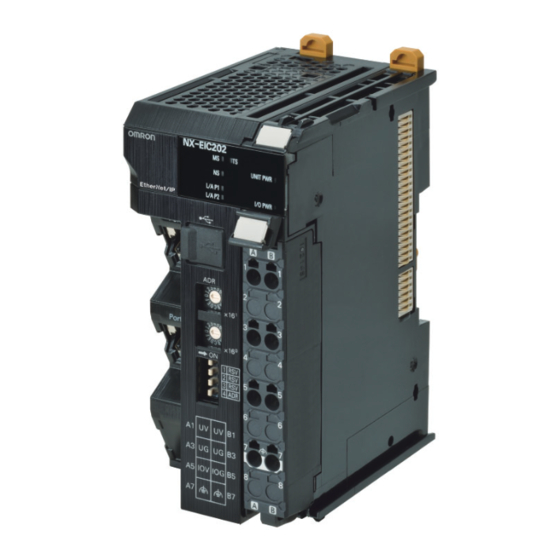
Function Marker attachment locations The locations where markers are attached. The markers made by OMRON are installed for the factory setting. Commercially available markers can also be installed. For details, refer to 6-1-8 Attaching Markers on page 6-18. Unit specifications The specifications of the Unit are engraved in the side of the casing. -
Page 73: Nx Units
Name Function Marker attachment locations The locations where markers are attached. The markers made by OMRON are installed for the factory setting. Commercially available markers can also be installed. NX bus connector This connector is used to connect each Unit. -
Page 74: End Cover
4 Part Names and Functions 4-1-3 End Cover An NX-END01 End Cover is connected to the end of the EtherNet/IP Slave Terminal. One End Cover is provided together with the EtherNet/IP Coupler Unit. *1. This is the shape for Units with lot numbers through December 2014. Letter Name Function... -
Page 75: Indicators
4 Part Names and Functions Indicators There are indicators to show the current operating status of the EtherNet/IP Coupler Unit. The appearance of the indicators has been changed for models released in or before September 2018 with lot numbers that represent the date of or after September 20, 2018. In this manual, those models are shown with the indicators after the change. - Page 76 4 Part Names and Functions NS Indicator The Network Status (NS) indicator indicates the status of the network. Color Status Meaning Green Tag data link communications have been estab- lished and normal communications are in progress. Flashing Normal communications are in progress, but tag data link communications have not been estab- lished.
- Page 77 4 Part Names and Functions UNIT PWR Indicator The UNIT PWR indicator shows the status of the Unit power supply. Color Status Meaning Green Unit power supplied Not lit No Unit power supply I/O PWR Indicator The I/O PWR indicator shows the status of the I/O power supply. Color Status Meaning...
- Page 78 4 Part Names and Functions Appearance Change of the Indicators The appearance of the indicators has been changed for models released in or before September 2018 with lot numbers that represent the date of or after September 20, 2018. See below for details on the applicable models and the changes.
-
Page 79: Hardware Switch Settings
4 Part Names and Functions Hardware Switch Settings This section describes the functions of the hardware switches (i.e., the rotary switches and the DIP switch) on the front panel of the EtherNet/IP Coupler Unit. 4-3-1 Rotary Switches The two rotary switches show a two-digit hexadecimal number. The setting range is 0x00 to 0xFF with the default setting 0x00. -
Page 80: Dip Switch
4 Part Names and Functions 4-3-2 DIP Switch Use DIP switch pin 3 to set the network interface type. Use DIP switch pin 4 to set the base of the IP address for the EtherNet/IP network. The other pins are reserved by the system. 1 RSV Name Setting... -
Page 81: Communications Connector And Peripheral Usb Port
4 Part Names and Functions Communications Connector and Periph- eral USB Port This section provides the specifications of the communications connectors and peripheral USB port on the front panel of the EtherNet/IP Coupler Unit. NX-EIC202 Peripheral USB port Communications connectors Communications Connectors Connect Ethernet cables to the communications connectors. -
Page 82: Terminal Blocks
4 Part Names and Functions Terminal Blocks The terminal block on the EtherNet/IP Coupler Unit is a removable screwless clamping terminal block that allows you to easily connect and remove the wiring. The Unit power supply, I/O power supply, and ground wire are connected to this screwless clamping terminal block. - Page 83 4 Part Names and Functions Applicable Terminal Blocks for Each Model The terminal blocks that you can use with each model of the EtherNet/IP Coupler Unit are given in the following table. Terminal block Unit model number Terminal block Number of Ground terminal Terminal current model number...
-
Page 84: Din Track Contact Plate
4 Part Names and Functions DIN Track Contact Plate There is a DIN Track contact plate in the section on the back of the EtherNet/IP Coupler Unit that comes into contact with the DIN Track. This plate is connected internally to the functional ground terminal on EtherNet/IP Coupler Unit. This means that the functional ground terminal will be electrically connected to the DIN Track. -
Page 85: Designing The Power Supply System
Designing the Power Supply Sys- This section describes how to design the power supply system for the EtherNet/IP Slave Terminal. 5-1 Power Supply System and Design Concepts ..... . . 5-2 5-1-1 Power Supply System and Types of Power Supplies . -
Page 86: Power Supply System And Design Concepts
5 Designing the Power Supply System Power Supply System and Design Concepts This section describes the power supply system for an EtherNet/IP Slave Terminal and the design con- cepts. 5-1-1 Power Supply System and Types of Power Supplies Power Supply System Configuration Diagram An example of a power supply system configuration diagram for an EtherNet/IP Slave Terminal is shown below. -
Page 87: Nx-Series Power Supply-Related Units
For the specifications of NX-series power supply-related Units, refer to the NX-series System Units User’s Manual (Cat. No. W523). For information on the most recent lineup of NX Series power sup- ply-related Units, refer to NX-series catalogs or OMRON websites, or ask your OMRON representative. Unit name... - Page 88 5 Designing the Power Supply System Unit name Function Additional I/O Power Sup- This NX Unit provides additional I/O power supply. ply Unit Use this NX Unit in the following cases. (a) When the I/O power supply capacity is insufficient •...
-
Page 89: Design Concepts For Power Supply To The Ethernet/Ip Slave Terminal
5 Designing the Power Supply System Unit name Function I/O Power Supply Con- This NX Unit is used when there are not enough I/O power supply terminals for the nection Unit connected external devices that are connected to NX Units such as Digital I/O Units and Analog I/O Units. -
Page 90: Designing The Nx Unit Power Supply System
5 Designing the Power Supply System Designing the NX Unit Power Supply System This section describes how to design the NX Unit power supply to the EtherNet/IP Slave Terminal. 5-2-1 Procedure for Designing the NX Unit Power Supply System The total power consumption from the NX Unit power supply must not exceed the NX Unit power supply capacity of the Unit that supplies the NX Unit power. -
Page 91: Calculation Example For The Nx Unit Power Supply
5 Designing the Power Supply System NX Unit Power Supply Capacity and Restrictions The internal power supply circuits of the EtherNet/IP Coupler Unit or Additional NX Unit Power Sup- ply Unit supply the NX Unit power to the NX Units. The NX Unit power supply capacity does not include the NX Unit power consumption of the Ether- Net/IP Coupler Unit or Additional NX Unit Power Supply Units. - Page 92 5 Designing the Power Supply System Additional Information Excess or insufficiency in the NX Unit power supply capacity can be easily checked when the Unit configuration is created on the Edit Slave Terminal Configuration Tab Page on the Support Software. Use the following procedure to check the power supply capacity. On the Edit Slave Terminal Configuration Tab Page on the Support Software, select the Unit to supply NX Unit power.
-
Page 93: Designing The I/O Power Supply System
5 Designing the Power Supply System Designing the I/O Power Supply Sys- This section describes how to design the I/O power supply to the EtherNet/IP Slave Terminal. 5-3-1 I/O Power Supply Method There are the following two methods to supply the I/O power supply to the EtherNet/IP Slave Terminal depending on the type and model of the NX Units. -
Page 94: Designing The I/O Power Supply From The Nx Bus
5 Designing the Power Supply System 5-3-2 Designing the I/O Power Supply from the NX Bus Procedure for Designing the I/O Power Supply Make sure that the following design conditions are met when you design the I/O power supply from the NX bus. - Page 95 5 Designing the Power Supply System ●The total current consumption ●The total current consumption from the I/O power supply from the I/O power supply ●The total current consumption from the I/O must not exceed the must not exceed the power supply must not exceed the maximum current of the I/O maximum current of the I/O power supply.
- Page 96 5 Designing the Power Supply System Current consumption item Description Current consumption between This is the current that is consumed between the NX Units and the con- the NX Units and the connected nected external devices. external devices For example, this is the current consumed by a Digital Input Unit to supply power to photoelectric sensors or to turn ON the input circuits in the Digital Input Unit.
- Page 97 5 Designing the Power Supply System ● Total current consumption from the Units ● Units that are supplied I/O Example: that are supplied I/O power from the power from the Additional I/O EtherNet/IP Coupler Unit (total for (1) to Power Supply Unit (7) = 4 A) EtherNet/IP Coupler NX Units...
-
Page 98: Designing The I/O Power Supply From External Sources
5 Designing the Power Supply System the power supply systems are to be separated and then perform similar calculations to design the over- all system to meet the power supply conditions. 5-3-3 Designing the I/O Power Supply from External Sources Unlike supplying power from the NX bus, there is no specific design method for supplying I/O power from external sources. - Page 99 5 Designing the Power Supply System Irms τ 5 - 15 NX-series EtherNet/IP Coupler Unit User’s Manual (W536)
-
Page 100: Selecting External Power Supplies And Protective Devices
• Has double or reinforced insulation between the input and output. • Has an output voltage of 24 VDC (20.4 to 28.8 VDC). Recommended Power Supplies: S8JX Series (manufactured by OMRON) Calculating the Required Power Supply Capacity of the Unit Power Supply ... - Page 101 5 Designing the Power Supply System Blocks A block consists of the Unit that supplies the NX Unit power and the range of Units to which that Unit supplies the NX Unit power. For example, in the configuration in the following figure there are two blocks in the EtherNet/IP Slave Terminal: the block with the EtherNet/IP Coupler Unit and the block with the Additional NX Unit Power Supply Unit.
-
Page 102: Selecting The I/O Power Supplies
*1. Use an output voltage that is appropriate for the I/O circuits of the NX Units and the connected external devices. Recommended Power Supplies: S8JX Series (manufactured by OMRON) Calculating the Required Power Supply Capacity of the I/O Power Supply... -
Page 103: Selecting Protective Devices
5 Designing the Power Supply System Selecting Protective Devices Consider the following items when you select protective devices. • Protective device specifications (breaking/fusing, detection characteristics, steady current value, etc.) • Inrush current when power is turned ON • Inrush current when connected external devices turn ON and OFF *1. - Page 104 5 Designing the Power Supply System Installation Locations for Protective Devices Install protective devices for the Unit power supply and I/O power supply in the locations that are shown in the following figure. Block that is supplied I/O power from the Additional Block that is supplied I/O power from the EtherNet/IP I/O Power Supply Unit Coupler Unit...
- Page 105 5 Designing the Power Supply System • Using Unwired Unit Power Supply Terminals In this example, the current consumption from each power supply is as follows: Current consumption from Unit power supply: I_unit1 + I_unit2 ≤ Lowest rated current Current consumption from I/O power supply: I_io1 + I_io2 ≥ Lowest rated current Block that is supplied I/O power from the Additional Block that is supplied I/O power from the EtherNet/IP...
- Page 106 5 Designing the Power Supply System • When Total Current Consumption for All Blocks Does Not Exceed the Rated Current In this example, the current consumption from each power supply is as follows: Current consumption from Unit power supply: I_unit1 + I_unit2 ≤ Lowest rated current Current consumption from I/O power supply: I_io1 + I_io2 ≤...
- Page 107 Installation This section describes how to install the EtherNet/IP Slave Terminal. 6-1 Installing Units ..........6-2 6-1-1 Installation Precautions .
-
Page 108: Installation
6 Installation Installing Units This section describes how to mount Units to an EtherNet/IP Slave Terminal. 6-1-1 Installation Precautions To increase the reliability of the EtherNet/IP Slave Terminal and take complete advantage of its func- tionality, observe the following precautions. Installation Location Do not install the EtherNet/IP Slave Terminal in the following locations. -
Page 109: Installation Orientation
6 Installation Control panel EtherNet/IP Slave Terminal Louver Accessibility for Operation and Maintenance • To ensure safe access for operation and maintenance, separate the EtherNet/IP Slave Terminal as much as possible from high-voltage equipment and power machinery. • If will be easy to operate the EtherNet/IP Slave Terminal if it is mounted at a height of 1.0 to 1.6 m above the floor. - Page 110 6 Installation Wiring Ducts Whenever possible, route I/O wiring through wiring ducts. Install mounting bases so that it is easy to wire the I/O Units through ducts. It is handy to have the ducts at the same height as the EtherNet/IP Slave Terminal. Duct 20 mm min EtherNet/IP...
- Page 111 6 Installation Routing Wiring Ducts Install the wiring ducts at least 20 mm away from the tops of the devices and any other objects (e.g., top of the panel, other wiring ducts, structural supports, and components) to provide enough space for air circulation and replacement of Units.
-
Page 112: Preparations For Installation
You must install the EtherNet/IP Coupler Unit and NX Units on a DIN Track. The following products are recommended. Name Model Manufacturer Remarks 35-mm DIN PFP-50N OMRON Corporation • Length: 50 cm Track • Material: Aluminum • Surface treatment: Insulated PFP-100N OMRON Corporation • Length: 100 cm •... - Page 113 6 Installation DIN Tracks PFP-100N/50N DIN Track 7.3±0.15 35±0.3 27±0.15 15(5) 1000(500)* *1 PFP-50N dimensions are given in parentheses. NS 35/7,5 PERF R0.8 R0.8 NS 35/15 PERF 15° R1.25 R1.25 End Plate PFP-M (Two) CLIPFIX 35 (Two) 6 - 7 NX-series EtherNet/IP Coupler Unit User’s Manual (W536)
-
Page 114: Installation Orientation
6 Installation 6-1-3 Installation Orientation An EtherNet/IP Slave Terminal can be installed in any of the following six orientations. (A) is the upright installation direction and (B) to (F) are installation directions other than upright. Down However, there are restrictions on the installation orientation of the EtherNet/IP Coupler Unit due to the ambient operating temperature and the NX Unit power supply capacity. -
Page 115: Installing The Ethernet/Ip Coupler Unit
6 Installation 6-1-4 Installing the EtherNet/IP Coupler Unit This section describes how to install the EtherNet/IP Coupler Unit. Precautions for Safe Use • Always turn OFF the power supply before installing the Unit. If the power supply is not OFF, the Unit may malfunction or may be damaged. •... - Page 116 6 Installation Install the DIN Track. • Using a PFP-50N/100N DIN Track Use one M4 screw for each three holes in the DIN Track. Ensure the head of each screw is at least 2 mm below the top of the DIN Track to prevent damage to units. There must be a screw for each interval of 105 mm or less.
- Page 117 6 Installation Press the EtherNet/IP Coupler Unit firmly against the DIN Track until you hear the DIN Track mounting hook lock into place. After you mount the EtherNet/IP Coupler Unit, check to be sure that it is securely mounted on the DIN Track.
-
Page 118: Installing And Connecting Nx Units
6 Installation 6-1-5 Installing and Connecting NX Units This section describes how to mount NX Units to the EtherNet/IP Coupler Unit and how to connect NX Units to each other. Precautions for Safe Use • Always turn OFF the power supply before mounting the NX Units. If the power supply is not OFF, the Unit may malfunction or may be damaged. - Page 119 6 Installation Unit hookup guides Unit hookup guides Slide the NX Unit in on the hookup guides. Press the NX Unit with a certain amount of force against the DIN Track until you hear the DIN Track mounting hook lock into place. When you mount the NX Unit, it is not necessary to release the DIN track mounting hook on the NX Unit.
- Page 120 6 Installation Unit hookup guides Unit hookup guides Slide the NX Unit in on the hookup guides. Press the NX Unit with a certain amount of force against the DIN Track until you hear the DIN Track mounting hook lock into place. When you mount the NX Unit, it is not necessary to release the DIN track mounting hook on the NX Unit.
-
Page 121: Mounting The End Cover
6 Installation 6-1-6 Mounting the End Cover Always mount an End Cover to the end of the Slave Terminal. Precautions for Safe Use • Always turn OFF the power supply before mounting the End Cover. If the power supply is not OFF, the Unit may malfunction or may be damaged. - Page 122 6 Installation Precautions for Correct Use The End Cover may not be mounted properly to the DIN Track if the protrusions on the back of the End Cover that are marked in the left below figure interfere with the screw that fixes the DIN Track as shown in the right below figure.
-
Page 123: Mounting The End Plates
Slave Terminal to secure the Slave Terminal. If you do not secure it, the EtherNet/IP Slave Ter- minal may be damaged or malfunction. Using PFP-M (OMRON) To mount an End Plate, 1) hook the bottom of it on the bottom of the DIN Track and 2) rotate the End Plate to hook the top of it on the top of the DIN Track. -
Page 124: Attaching Markers
Markers can be attached to EtherNet/IP Coupler Units, NX Units, and terminal blocks on NX Units to identify them. The plastic markers made by OMRON are installed for the factory setting. The ID information can be written on them. Commercially available markers can also be installed. -
Page 125: Removing Units
DEK 5/8 Special marker printer UM EN BLUEMARK X1 PrintJet PRO The markers made by OMRON cannot be printed on with commercially available special printers. 6-1-9 Removing Units Precautions for Safe Use Always turn OFF the power supply before removing any Unit. - Page 126 6 Installation Remove the Unit with either (a) or (b) below. (a) For an EtherNet/IP Coupler Unit, place your fingers on the protrusions on the EtherNet/IP Coupler Unit and pull it straight forward. (b) For an NX Unit, place your fingers on the protrusions on more than one NX Unit, including the NX Unit to remove, and pull the NX Units straight forward.
-
Page 127: Assembled Appearance And Dimensions
6 Installation 6-1-10 Assembled Appearance and Dimensions Installation Dimensions End Cover Coupler Unit End Plate 0.55 NX Units End Plate DIN Track 104.5 65.2 W+(C)+(C) (Unit: mm) (Unit: mm) *1. The dimension is 1.35 mm for Communications Coupler Units with lot numbers through December 2014 or for NX Units with 12-mm widths with lot numbers through December 2014. - Page 128 6 Installation Calculation Example for the Configuration Width of an EtherNet/IP Slave Ter- minal NX Units: Digital Input Units with 4 inputs each NX Units: End Cover Temperature Input Units EtherNet/IP Coupler Unit with 4 inputs each The widths of the Units in the example EtherNet/IP Slave Terminal configuration and the total config- uration width are given below.
- Page 129 6 Installation Installation Height The installation height of the EtherNet/IP Slave Terminal depends on the model of DIN Track and on the models of NX Units that are mounted. Also, additional space is required for the cables that are connected to the Unit. Allow sufficient depth in the control panel and allow extra space when you mount the EtherNet/IP Slave Terminal.
-
Page 130: Control Panel Installation
6 Installation Control Panel Installation To ensure system reliability and safety, the system must be designed and configured according to the installation environment (temperature, humidity, vibration, shock, corrosive gases, overcurrent, noise, etc.). 6-2-1 Temperature Panels have been reduced in size due to space-saving and miniaturization in devices and systems, and the temperature inside the panel may be at least 10 to 15°C higher than outside the panel. - Page 131 6 Installation Forced Ventilation by Fan at Top of Panel EtherNet/IP Slave Terminal EtherNet/IP Slave Terminal Air filter Forced Ventilation Method Forced Air Circulation by Fan in Closed Panel EtherNet/IP Slave Terminal EtherNet/IP Slave Terminal Forced Circulation Method ...
-
Page 132: Humidity
6 Installation 6-2-2 Humidity Rapid temperature changes can cause condensation to occur, resulting in malfunctioning due to short-circuiting. When there is a possibility of this occurring, take measures against condensation, such as leaving the EtherNet/IP Slave Terminal power ON at night or installing a heater in the control panel to keep it warmer. - Page 133 6 Installation Example of Recommended Equipment Arrangement EtherNet/IP Slave Terminal Control panel Control panel High-voltage power panel Example of Poor Equipment Arrangement EtherNet/IP Slave Terminal Control panel Control panel High-voltage power panel Examples of Equipment Arrangement in Panel with High-voltage Devices Arrangement of EtherNet/IP Slave Terminal and Cables Observe the following points.
- Page 134 6 Installation • Keep the wiring between the transformer and the EtherNet/IP Slave Terminal as short as possible, twist the wires well, and keep the wiring separate from high-voltage and power lines. Supplying I/O Power from the NX Bus Power circuits Power supply for general operations circuits I/O power supply for EtherNet/IP Slave Terminal...
- Page 135 6 Installation • Never bundle I/O cables with high-voltage or power lines, and do not route them in close proximity or parallel to such lines. If output signal lines must be routed in close proximity to such lines, place them in separate ducts or conduits.
- Page 136 6 Installation Partition Signal Signal Signal Power cables cables cables supply cables (group A) (group B) (group C) Signal cables Signal cables Signal cables Power supply cables Power supply cables Partitioning Methods for Signal and Power Supply Cables • To avoid overheating the conduits when using conduits for wiring, do not place wires for a single circuit in separate conduits.
-
Page 137: Grounding
6 Installation High-voltage power panel Metal tubing Power lines Power lines 200 mm EtherNet/IP EtherNet/IP Slave Slave Ground to 100 Ω or less 200 mm Terminal Terminal Example: Separating EtherNet/IP Slave Terminal from Power Lines Other Precautions Some models of Digital Input Units and Digital Output Units have polarity. Make sure that you wire the polarity correctly. - Page 138 6 Installation Grounding Methods EtherNet/IP EtherNet/IP EtherNet/IP Slave Slave Slave Terminal Terminal Terminal DIN Track DIN Track DIN Track Other Other Other device device device Ground to 100 Ω or less (c) Common Ground: Incorrect (a) Independent Grounds: Best (b) Common Ground: Acceptable If the DIN Track is made of steel and the surface is not treated to produce an insulating material, you can omit grounding the functional ground terminal on any Unit that has one, as shown in the follow-...
-
Page 139: Wiring
Wiring This section describes how to wire the EtherNet/IP Slave Terminal. 7-1 EtherNet/IP Network Wiring ........7-2 7-1-1 Installation Precautions . -
Page 140: Ethernet/Ip Network Wiring
7 Wiring EtherNet/IP Network Wiring This section describes how to install the EtherNet/IP network. 7-1-1 Installation Precautions Basic precautions for the installation of EtherNet/IP networks are provided below. Precautions when Installing a Network • When you install an EtherNet/IP network, take sufficient safety precautions and perform the installa- tion according to all applicable standards and specifications. -
Page 141: Pin Arrangement Of Communications Connectors On The Ethernet/Ip Coupler Unit
7 Wiring Precautions for Safe Use • Double-check all switches and other settings and double-check all wiring to make sure that they are correct before turning ON the power supply. Use the correct wiring parts and tools when you wire the system. •... -
Page 142: Connecting Communications Cables And Connectors
7 Wiring 7-1-4 Connecting Communications Cables and Connectors Use straight connections for the communications cables and connectors, as shown below. Wire color Wire color Pin No. Pin No. White-Green White-Green Green Green White-Orange White-Orange Blue Blue White-Blue White-Blue Orange Orange White-Brown White-Brown Brown... - Page 143 7 Wiring EtherNet/IP master Communications cable EtherNet/IP Slave Terminals Last EtherNet/IP Slave Terminal Precautions for Correct Use • The cable between any two nodes (L1, L2 ... Ln) must be 100 m or less. • Do not exceed the ranges that are given in the specifications for the communications dis- tance and number of connected Units.
-
Page 144: Connecting The Power Supply And Ground Wires
7 Wiring Connecting the Power Supply and Ground Wires This section describes how to wire the power supplies and ground the EtherNet/IP Slave Terminal. 7-2-1 Wiring the EtherNet/IP Coupler Unit The wiring of the power supply and ground to the EtherNet/IP Coupler Unit is shown in the following fig- ure. -
Page 145: Wiring The Power Supply To The Ethernet/Ip Slave Terminal
7 Wiring Functional Ground Terminals These are the functional ground terminals. Connect the ground wire to one of these terminals. The details are given in the following table. Terminal number indication Terminal symbol Description A7 or B7 Connect the ground wire to either the A7 or B7 ter- minal. - Page 146 7 Wiring DIN Track Contact Plates A Unit that has a ground terminal also has a DIN Track contact plate on the back of the Unit. Unit side Ground terminal DIN Track contact plate Connected inside the Unit. The DIN Track contact plate is connected internally to the ground terminal on the Unit. This means that the ground terminal will be electrically connected to the DIN Track.
- Page 147 If the ground wire for the EtherNet/IP Coupler Unit or an NX Unit with a ground terminal is shared with power equipment, noise will adversely affect the Units. You can use OMRON NX-AUX01 DIN Track Insulation Spacers with PFP-50N or PFP-100N DIN Tracks to isolate an EtherNet/IP Slave Terminal from the control panel.
- Page 148 Screws, M4×10 DIN Track Control panel • DIN Track Insulation Spacers NX-AUX01 (OMRON Corporation) 14.8 Precautions for Correct Use If you use DIN Track Insulation Spacers to install an EtherNet/IP Slave Terminal, the height will be increased by approximately 10 mm. Make sure that the EtherNet/IP Slave Terminal and con- necting cables do not come into contact with other devices.
-
Page 149: Precautions For Wiring The Ethernet/Ip Slave Terminal Together With Computers And Other Peripheral Devices
7 Wiring 7-2-4 Precautions for Wiring the EtherNet/IP Slave Terminal Together with Computers and other Peripheral Devices Caution When you connect a computer or other peripheral device to the following Unit, either ground the 0-V side of the external power supply (i.e. Unit power supply) or do not ground it at all. •... - Page 150 7 Wiring WARNING Make sure that the voltages and currents that are input to the Units and slaves are within the specified ranges. Inputting voltages or currents that are outside of the specified ranges may cause failure or fire. Applicable Wires The wires that you can connect to the screwless clamping terminal block are twisted wires, solid wires, and ferrules that are attached to the twisted wires.
- Page 151 7 Wiring Applica- ble wire Terminal Manufac- Ferrule Crimping tool types turer model (AWG)) Terminals Weidmuller H0.14/12 0.14 (#26) Weidmuller (The figure in parentheses is the appli- other than cable wire size.) H0.25/12 0.25 (#24) ground ter- H0.34/12 0.34 (#22) PZ6 Roto (0.14 to 6 mm , AWG26 to 10) minals...
- Page 152 7 Wiring Precautions for Correct Use • Use cables with suitable wire sizes for the carrying current. There are also restrictions on the current due to the ambient temperature. Refer to the manuals for the cables and use the cables correctly for the operating environment. •...
- Page 153 7 Wiring Recommended screwdriver Model Manufacturer SZF 0-0,4X2,5 Phoenix Contact Connecting Ferrules Insert the ferrule straight into the terminal hole. It is not necessary to press a flat-blade screwdriver into the release hole. Ferrule After you make a connection, make sure that the ferrule is securely connected to the terminal block. ...
- Page 154 7 Wiring Remove the flat-blade screwdriver from the release hole. After you make a connection, make sure that the twisted wire or the solid wire is securely connected to the terminal block. Precautions for Safe Use • Do not press the flat-blade screwdriver straight into the release hole. Doing so may break the terminal block.
- Page 155 7 Wiring Securing Wires It is necessary to secure wires to the screwless clamping terminal block depending on the wire types that are used or the current flows on the wires. The following table gives the necessity for securing wires. Terminals Wire type Twisted wires...
- Page 156 7 Wiring Bundle the wires with a cable tie and secure them to the screwless clamping terminal block. Secure wires within the range of 30 mm from the screwless clamping terminal block. 30 mm 7 - 18 NX-series EtherNet/IP Coupler Unit User’s Manual (W536)
- Page 157 7 Wiring Removing Wires Use the following procedure to remove the wires from the terminal block. The removal method is the same for ferrules, twisted wires, and solid wires. If wires are secured firmly to the terminal block, release them first. Press the flat-blade screwdriver diagonally into the release hole.
- Page 158 7 Wiring Precautions for Safe Use • Do not press the flat-blade screwdriver straight into the release hole. Doing so may break the terminal block. • When you insert a flat-blade screwdriver into a release hole, press it down with a force of 30 N max.
- Page 159 7 Wiring Attaching a Terminal Block Mount the terminal block hook on the guide at the bottom of the EtherNet/IP Coupler Unit, lift up the terminal block, and press in on the top of the terminal block until you hear it engage. The terminal block will click into place on the Unit.
- Page 160 7 Wiring Types of Coding Pins There are two types of Coding Pins, both with their own unique shape: one for terminal blocks and one for Units. Three pins come with each runner. For Unit For terminal block Runners Coding Pins (Use this part.) Use the following Coding Pins.
- Page 161 7 Wiring Unit Terminal block Holes used by Holes used by OMRON OMRON Holes for incorrect Holes for incorrect attachment prevention attachment prevention (pin locations) (pin locations) ○: Pin inserted Pin locations for Pin locations for Unit terminal block Pattern No.1...
- Page 162 Precautions for Correct Use • OMRON uses the holes other than No. 1 to 6 in the figure on the previous page. If you insert a Coding Pin into one of the holes used by OMRON on the terminal block side, it would be impossible to mount the terminal block on a Unit.
- Page 163 7 Wiring Unit 7 - 25 NX-series EtherNet/IP Coupler Unit User’s Manual (W536)
-
Page 164: Connecting Usb Cable
7 Wiring Connecting USB Cable The EtherNet/IP Coupler Unit can be connected directly to a computer in which the Support Software is installed through a USB cable. Connection Method Use a commercially available USB certified cable to connect the computer in which the Support Soft- ware is installed to the peripheral USB port on the EtherNet/IP Coupler Unit. - Page 165 7 Wiring Making Settings with the Support Software The connection between the EtherNet/IP Coupler Unit and computer is set up with the Support Soft- ware. Refer to 2-3-2 Connection Method and Procedures on page 2-9 for the procedure to connect to the Support Software.
-
Page 166: Wiring External Signal Lines
7 Wiring Wiring External Signal Lines Refer to the sections on wiring in the user’s manuals for individual NX Units for information on wiring the external I/O signal lines between the external devices and the NX Units. For precautions on wiring in control panels, refer to 6-2 Control Panel Installation on page 6-24. 7 - 28 NX-series EtherNet/IP Coupler Unit User’s Manual (W536) -
Page 167: Ethernet/Ip Communications
EtherNet/IP Communications This section provides an introduction to EtherNet/IP communications. 8-1 EtherNet/IP Functions ......... . 8-2 8-1-1 Implicit Message Communications . -
Page 168: Ethernet/Ip Functions
8 EtherNet/IP Communications EtherNet/IP Functions The EtherNet/IP Coupler Unit uses implicit and explicit message functions to exchange I/O data and perform configuration settings. Connection-based cyclic, class 1, implicit messages are used to exchange I/O information. Connection-based, class 3 explicit messages and connectionless UCMM explicit messages are used for configuration and other non-cyclic communications. -
Page 169: Explicit Message Communications
8 EtherNet/IP Communications more than one EtherNet/IP master. For an EtherNet/IP Coupler Unit, a connection I/O type of input/output is equivalent to an exclusive owner connection. Input Only Connection An input only connection is used to connect to an EtherNet/IP slave that has input data so that the input data can be received from the EtherNet/IP slave. -
Page 170: Tag Data Links
8 EtherNet/IP Communications Tag Data Links Tag data links enable cyclic data exchanges on an EtherNet/IP network between PLCs and EtherNet/IP Coupler Units. The settings for tag data links are made using the Network Configurator or other Support Software that can edit settings for EtherNet/IP. -
Page 171: Tag Data Link Data Areas
8 EtherNet/IP Communications Starting and Stopping Tag Data Links Tag data links are automatically started when the data link parameters are downloaded from the Net- work Configurator. Thereafter, tag data links can be stopped and started for the entire network or indi- vidual devices from the Network Configurator. - Page 172 8 EtherNet/IP Communications Example In the following example, input tag a at the originator is a tag set named Input_100 and output tag i is a tag set named Output_148. A connection is set between these two tag sets. EtherNet/IP Slave Terminal Originator Device IP address: #...
-
Page 173: Creating Tag Data Links
8 EtherNet/IP Communications 8-2-2 Creating Tag Data Links Use the following procedure with the Network Configurator if tag data link functionality is used with an EtherNet/IP Unit. Refer to 9-5 Setting Tag Data Links on page 9-36 for detailed steps on creating tag data links. - Page 174 8 EtherNet/IP Communications 8 - 8 NX-series EtherNet/IP Coupler Unit User’s Manual (W536)
-
Page 175: Setting Up Slave Terminals
Setting Up Slave Terminals This section describes the procedures used to set up Slave Terminals. 9-1 Settings and Setting Procedures ....... . . 9-3 9-1-1 Items to Set . - Page 176 9 Setting Up Slave Terminals 9-6 Assigning Network Variables ........9-71 9-6-1 Basic I/O Mapping .
-
Page 177: Settings And Setting Procedures
Adjust the settings of the Slave Terminal with the configuration and operation uration and Operation Settings settings of the NX Units and EtherNet/IP Coupler Unit using Support Software. EtherNet/IP Data This data is set using a configuration tool such as the OMRON Network Configurator. Setting Description Setting IP Address Set the IP address of the EtherNet/IP Coupler Unit. - Page 178 9 Setting Up Slave Terminals EtherNet/IP Unit Support Software EtherNet/IP port Communications cable Ethernet cables Support Software EtherNet/IP Slave Terminal Peripheral USB port Network Configurator Ethernet switch Set EtherNet/IP configuration parameters. E.g. IP Address, tag data links, network variables. Connection to peripheral USB Connect to EtherNet/IP master port on EtherNet/IP Coupler Unit Support Software...
-
Page 179: Slave Terminal Parameters
9 Setting Up Slave Terminals 9-1-2 Slave Terminal Parameters Parameters must be set to ensure that the Slave Terminal operates as intended and performs data exchange with other EtherNet/IP devices. The settings are listed in the following table. Setting Description Slave Terminal Configuration NX Unit configuration infor-... - Page 180 9 Setting Up Slave Terminals 9-6 Assigning Network Variables on page 9-71 Additional Information You can use the NX Units for EtherNet/IP Coupler Units and EtherNet/IP Slave Terminals with the default settings. Refer to A-5 Application Procedure for the Default Settings on page A-52 for the application procedures for the default settings.
-
Page 181: Setting Slave Terminal Parameters
9 Setting Up Slave Terminals Setting Slave Terminal Parameters This section describes how to set the Slave Terminal parameters with Support Software. The Sysmac Studio is used as an example. For Support Software other than the Sysmac Studio, refer to the operation manual for the Support Soft- ware that you are using. - Page 182 9 Setting Up Slave Terminals Data Setting Settable Description Default range Device name This is the name of the EtherNet/IP Coupler Unit. E *** (* is a serial number from Use the EtherNet/IP Configuration Edit Tab Page to 001). change this setting. The default value is automatically generated based...
- Page 183 9 Setting Up Slave Terminals NX Units Data Name Settable Description Default range Device name The name of the NX Unit. N* (Where * is a serial number from 1) Model name This is the model number of the NX Unit. Product name This is the product name.
- Page 184 9 Setting Up Slave Terminals The Edit Slave Terminal Configuration Tab Page is displayed. Drag the NX Unit from the Toolbox to the Edit Configuration Pane and drop it on the Slave Ter- minal. Toolbox Unit Settings Pane Edit Slave Terminal Configuration Pane 9 - 10 NX-series EtherNet/IP Coupler Unit User’s Manual (W536)
-
Page 185: I/O Allocation Information
9 Setting Up Slave Terminals Item Description Edit Slave Terminal Configura- You can edit the Unit configuration information for the Slave Terminal tion Pane here. Unit Settings Pane This list displays the setting information for the currently selected Unit. • Edit I/O Allocation Settings button: Click this button to change the I/O allocation information. -
Page 186: I/O Allocation Information
9 Setting Up Slave Terminals 9-2-3 I/O Allocation Information The I/O allocation information maps the I/O data in the EtherNet/IP Coupler Unit to exchange with the tag data link. The Slave Terminal performs tag data link exchange with the CJ EtherNet/IP Units based on the I/O allocation information. - Page 187 9 Setting Up Slave Terminals Registering I/O Entries The I/O data assigned to an I/O entry mapping is called an I/O entry. Default values are assigned to the I/O entries in each I/O entry mapping. Some I/O entry mappings allow you to add or delete I/O entries.
- Page 188 9 Setting Up Slave Terminals formance. For example, if you use 10 NX Units, we recommend that you use the status that has “Status 15” in the data name. NX object I/O entry Regis- Subin- mapping Data name Function Data type Default tered by Index...
- Page 189 9 Setting Up Slave Terminals Details of I/O Data in the EtherNet/IP Coupler Unit This section describes the I/O data in detail. NX Unit Registration Status Data name Description NX Unit Registration Status This status tells whether the NX Units are registered in the Unit Configuration. The status is acquired for as many NX Units as the numeric suffix at the end of NX Unit Registration Status the data name.
- Page 190 9 Setting Up Slave Terminals NX Unit Message Enabled Status Data name Description NX Unit Message Enabled This status tells whether the NX Units can process message communications. Status 15 The status is acquired for as many NX Units as the numeric suffix at the end of NX Unit Message Enabled the data name.
- Page 191 9 Setting Up Slave Terminals NX Unit Error Status Data name Description NX Unit Error Status 15 This status tells whether an error exists on the NX Units. NX Unit Error Status 31 The status is acquired for as many NX Units as the numeric suffix at the end of NX Unit Error Status 63 the data name.
- Page 192 9 Setting Up Slave Terminals Slave Terminal Status Data name Description Slave Terminal Status This indicates the status conditions of the Slave Terminal. The following table shows the structure of the bits in the Slave Terminal status. Description Reserved Observation •...
- Page 193 9 Setting Up Slave Terminals Additional Information A detailed display of I/O Allocation can be found by right-clicking the EtherNet/IP Coupler Unit and selecting Display I/O Allocation from the menu. Refer to 9-6-2 Support Software I/O Allo- cation Functions on page 9-73 for more details. 9 - 19 NX-series EtherNet/IP Coupler Unit User’s Manual (W536)
- Page 194 9 Setting Up Slave Terminals Editing the I/O Allocation Settings You can edit the I/O allocations for the EtherNet/IP Coupler Unit and NX Units as necessary. In the Unit Settings Pane, click the Edit I/O Allocation Settings button. The Edit I/O Allocation Settings Pane is displayed over the Edit Slave Terminal Configuration Tab Page.
- Page 195 9 Setting Up Slave Terminals Name/Label Description I/O Entry Map- This is a mapping list of the I/O entries in the corresponding Unit. ping List The I/O entry mapping list shows up to four inputs and outputs respectively. The I/O entry mapping list shows the following items. •...
-
Page 196: Unit Operation Settings
9 Setting Up Slave Terminals Select the I/O data to add. Note The sequence of your selection determines the order in the I/O allocation table. Click the OK button. The selected I/O entry is added to the I/O allocation table. Click the Apply button or OK button to confirm the current settings. -
Page 197: Unit Application Data
9 Setting Up Slave Terminals Unit Operation Settings for the NX Unit The settings that are available depend on the type of the NX Unit. For example, Digital Input Units have a setting for the input filter value, and Digital Output Units have a setting for the output value at load rejection. -
Page 198: Support Software Functions Used As Required
9 Setting Up Slave Terminals 9-2-6 Support Software Functions Used as Required You can use the following functions on the Support Software. • Getting NX Unit serial numbers • Comparing and merging with actual Unit configuration of the Slave Terminal •... - Page 199 9 Setting Up Slave Terminals Precautions for Correct Use You can read only the Unit configuration in the Slave Terminal by comparing and merging with the actual Unit configuration. You cannot read the I/O allocation information, Unit operation set- tings, and Unit application data. Getting NX Unit Serial Numbers If the serial number check method that is set in the EtherNet/IP Coupler Unit is set to Setting = Actual device, you must download the Unit configuration information in which the serial numbers for the NX...
- Page 200 9 Setting Up Slave Terminals Enter a file name, and then click the Save button. An NX Unit setting file with an .nsf extension is saved. To import a file, select Import NX Unit Settings and Insert New Unit in step 1, and specify the file to import.
- Page 201 9 Setting Up Slave Terminals Additional Slave Terminal configurations can be accessed with the drop down selection menu. 9 - 27 NX-series EtherNet/IP Coupler Unit User’s Manual (W536)
-
Page 202: Transferring And Comparing Settings
9 Setting Up Slave Terminals Transferring and Comparing Settings This section describes how to transfer and compare Slave Terminal settings that you set on the Support Software. The Sysmac Studio is used as an example. For Support Software other than the Sysmac Studio, refer to the operation manual for the Support Soft- ware that you are using. -
Page 203: Comparing Settings
9 Setting Up Slave Terminals Click the Yes button. The specified data is transferred. Precautions for Correct Use • The EtherNet/IP master may detect an error when the Slave Terminal is restarted after the Slave Terminal setting information is transferred with a direct USB connection between the Support Software and EtherNet/IP Coupler Unit. - Page 204 9 Setting Up Slave Terminals Right-click the target EtherNet/IP Coupler Unit and select Coupler Connection (USB) − Com- pare from the pop-up menu. The results of the comparison are displayed as shown below. When the Settings Are the Same: When the Settings Are Different: 9 - 30 NX-series EtherNet/IP Coupler Unit User’s Manual (W536)
-
Page 205: Setting Ip Address
9 Setting Up Slave Terminals Setting IP Address There are several ways to set the IP address of the Slave Terminal. Specify the IP address setting method as follows with the rotary switches. Set value (hex) IP address setting method •... - Page 206 9 Setting Up Slave Terminals Select Tools - Setup TCP/IP Configuration to display the following Setup TCP/IP Configura- tion Dialog Box, and set the TCP/IP Configuration for the target device. In the following exam- ple, the settings are all at their default values. Enter the IP address to set and press the Get from the Device button.
-
Page 207: Getting The Ip Address From The Bootp Server With The Network Configurator
9 Setting Up Slave Terminals The following TCP/IP parameters are not used: • Preferred DNS server • Alternate DNS server • Domain name The following TCP/IP parameters are preset: • Link parameter - Link speed preset to 100 Mbps • Link parameter - Duplex preset to Full duplex Precautions for Correct Use •... -
Page 208: Directly Setting The Ip Address Using Hardware Switches
9 Setting Up Slave Terminals Select the Get the IP address via BOOTP server option. In the New Configuration area, click the Set to the Device button to send the new setting to the applicable device. The applicable device is the device specified in the Target IP Address Box. The device must be reset to enable the transferred setting. -
Page 209: Getting An Ip Address From The Bootp Server
9 Setting Up Slave Terminals • An error will occur if the same IP address is set for another device. • An error will occur if the IP address is not within the setting range. 9-4-4 Getting an IP Address from the BOOTP Server If the rotary switches are set to FF hex, the IP address gotten from the BOOTP server is enabled. -
Page 210: Setting Tag Data Links
Start with Settings Inherited is selected. Starting from the Windows Start Menu To start the Network Configurator, select OMRON - CX-One - Network Configurator for Ether- NetIP - Network Configurator from the Windows Start Menu. When the Network Configurator starts, the following window is displayed. - Page 211 9 Setting Up Slave Terminals Main Window The Main Window consists of a Hardware List and a Network Configuration Pane, as shown in the fol- lowing diagram. Network Configuration Pane: This is used to configure the network by placing devices to be configured and monitored. Hardware List: This is a list of devices that you can add to the network.
-
Page 212: Tag Data Link Setting Procedure
9 Setting Up Slave Terminals To change the name displayed in the Network Tab Page, select Network - Property. You can change the name set in the Comment Field of the Network Property Dialog Box. 9-5-2 Tag Data Link Setting Procedure This section describes the procedure to set tag data links (i.e., connection information). -
Page 213: Registering Devices
9 Setting Up Slave Terminals Download the tag data link parameters. Refer to 9-5-8 Downloading Tag Data Link Parameters on page 9-63. Make sure that the tag data links are operating normally by using the indicators for the Ether- Net/IP Unit (refer to 12-2-1 Checking for Errors and Troubleshooting with the Indicators on the EtherNet/IP Coupler Unit on page 12-3) and the Network Configurator monitor functions (refer to 12-3-1 Checking Status with the Network Configurator on page 12-10). -
Page 214: Determine Tag Sizes
9 Setting Up Slave Terminals Right-click the registered device’s icon to display the pop-up menu, and select Change Node Address. Set the IP address to match the node address (IP address) actually used in the device and click the OK button. Repeat steps 1 to 3, and register all of the devices that participate in the tag data links. - Page 215 9 Setting Up Slave Terminals Confirm the upload success and check the updated sizes. Right-click the EtherNet/IP Coupler Unit, select Parameter - Edit. The Edit Device Parameters Dialog Box should appear and indi- cate the Input and Output sizes. Using the Support Software to Examine I/O Allocations Use the following steps to view the input and output tag sizes that are configured in the EtherNet/IP Coupler Unit.
-
Page 216: Creating Tags And Tag Sets
9 Setting Up Slave Terminals The I/O allocation indicates the input and output tag sizes (bytes) for the present configuration. Additional Information Refer to 9-6-2 Support Software I/O Allocation Functions on page 9-73 for more details. 9-5-5 Creating Tags and Tag Sets The tag sets and set member tags required to create connections for a registered EtherNet/IP Unit must be created. - Page 217 9 Setting Up Slave Terminals 1) Creating Tags and Tag Sets with the Network Configurator’s Device Parameter Editing Function Precautions for Correct Use The network variables described in this section can be used only if you are using a □ □...
- Page 218 9 Setting Up Slave Terminals Creating a Tag Set Double-click the icon of the device for which to create a tag set to display the Edit Device Parameters Dialog Box. Right-click the icon to display the pop-up menu, and select Parameter –...
- Page 219 9 Setting Up Slave Terminals Creating and Adding Tags Click the Edit Tags button. The Edit Tags Dialog Box is displayed. Register the input (consume) tags and output (produce) tags separately. Click the In - Consume Tab, and then click the New button. The Edit Tag Dialog Box is dis- played.
- Page 220 9 Setting Up Slave Terminals CPU Unit’s data area Address (Text to input in Name Field.) CIO Area 0000 to 6143 Holding Area H000 to H511 Work Area W000 to W511 DM Area D00000 to D32767 EM Area Bank 0 hex E0_00000 to E0_32767 Bank 18 hex E18_00000 to E18_32767...
- Page 221 9 Setting Up Slave Terminals When you are finished registering the required tags, click the OK button at the bottom of the Edit Tags Dialog Box. At this point, a confirmation dialog box is displayed to check whether the registered tag names are used as the tag set names.
- Page 222 9 Setting Up Slave Terminals Changing and Registering Tag Sets The following dialog box will be displayed when the tags in the Edit Tags Dialog Box are regis- tered directly as tag sets. If an input tag has already been registered in an input tag set, and you want to change its regis- tration to a different input tag set, it is necessary to delete the tag from the tag set in which it was originally registered.
- Page 223 9 Setting Up Slave Terminals At this point, a confirmation dialog box will be displayed to confirm that you want to delete the selected tag set and the tags contained in that tag set. If the No button is clicked, only the tag set will be deleted. Click the No button. To edit a registered tag set and add tags, either double-click the tag set, or select the tag set and click the Edit button.
- Page 224 9 Setting Up Slave Terminals The Tag List on the left side of the dialog box shows the tags that are already registered, and the Candidate Tag List on the right side of the dialog box shows the other tags that are not regis- tered yet.
- Page 225 9 Setting Up Slave Terminals Select the tags that you want to add from the Candidate Tag List and click the button. If you include the Controller status in the tag set, you can register up to only seven tags, and two bytes are added to the size.
- Page 226 9 Setting Up Slave Terminals Importing Symbols to the Network Configurator Start the CX-Programmer and open the project that was saved. Note When multiple copies of the CX-Programmer are running at the same time, it is possible to import only from the CX-Programmer project that was started first.
- Page 227 9 Setting Up Slave Terminals Click the Import button on the Tag Sets Tab Page of the Edit Device Parameter Dialog Box. A confirmation dialog box is displayed that asks you how you want to import the variables as shown below. To import all symbols with a Network Publish attribute, click the Yes button.
- Page 228 9 Setting Up Slave Terminals To place more than one input symbol (input tag) imported from the CX-Programmer into one tag set, you must delete the input tags that were registered to separate input tag sets. Select the tag sets for the symbols that are included in the one tag set and click the Delete but- ton.
- Page 229 9 Setting Up Slave Terminals Importing the Tag and Tag Set CSV File with the CX-Programmer □ □ In the project global symbol table for the CJ2H-CPU6 -EIP or CJ2MCPU3 , right-click and select Import Network Variable from the pop-up menu. 9 - 55 NX-series EtherNet/IP Coupler Unit User’s Manual (W536)
-
Page 230: Connection Settings
9 Setting Up Slave Terminals You can add a tag as a network symbol by selecting and executing the CSV file exported using the Network Configurator. Precautions for Correct Use The following precautions apply when importing. • Tags that have a specified I/O memory address cannot be imported. •... - Page 231 9 Setting Up Slave Terminals Connection Settings (Connections Tab Page) Registering Devices in the Register Device List Double-click the icon of the device for which to make originator settings in the Network Configu- ration Pane of the Network Configurator. The Edit Device Parameters Dialog Box is displayed. Right-click the icon to display the pop-up menu, and select Parameter - Edit.
- Page 232 9 Setting Up Slave Terminals Target node IDs are assigned to devices registered in the Register Device List. This target node ID determines the location in the originator node PLC of the Target Node PLC Operating Flag, Target Node PLC Error Flag, Registered Target Node Flag, and Normal Target Node Flag.
- Page 233 9 Setting Up Slave Terminals Setting Description Connection I/O Type Select one of the following: Input/Output, Input Only, or Listen Only. Connection Type Selects whether the data is sent in multicast or unicast (point-to- point). The default setting is multicast. •...
- Page 234 9 Setting Up Slave Terminals Setting Description Connection Name Sets a name for the connection. (32 characters max.) After you make all of the settings, click the OK button. Precautions for Correct Use If you set a tag data link with a short packet interval (RPI) when many NX Units are connected to the EtherNet/IP Slave Terminal, a Tag Data Link Timeout may occur depending on the load conditions on the EtherNet/IP Slave Terminal.
- Page 235 9 Setting Up Slave Terminals Setting Description Originator Variable Select and allocate the originator node’s tag set. • In: Select the originator’s input (consume) tag set. • Out: Select the originator’s output (produce) tag set. Connection Type Select whether the data is sent in multi-cast or unicast (point-to-point) form. The default setting is multi-cast.
- Page 236 9 Setting Up Slave Terminals Confirming the Connections Settings An overview of the connections that were set in the Register Device List is displayed in the Con- nections Tab Page. Click the OK button. The following diagram is displayed. Indicates the IP address of the originator where the connection was set.
-
Page 237: Tag Data Parameters And Specifications
9 Setting Up Slave Terminals 9-5-7 Tag Data Parameters and Specifications Item Specification Communications type Standard EtherNet/IP implicit communications (connection-type cyclic communications) Setting method After you have set the tags, tag sets, and connections with the Network Configurator, you must download the tag data link parameters to all devices on the EtherNet/IP net- work. - Page 238 9 Setting Up Slave Terminals • Do not disconnect the Ethernet cable or reset or turn OFF the power to the EtherNet/IP Unit during the parameter download. • Tag data links (data exchange) between relevant nodes is stopped during a download. Before you download data in RUN mode, make sure that it will not affect the controlled sys- tem.
- Page 239 9 Setting Up Slave Terminals Click the Yes button to download the tag data link parameters to the EtherNet/IP Unit. The fol- lowing dialog box is displayed if any of the CPU Units is not in PROGRAM mode. If the Download after changed to Program mode button is clicked, all CPU Units are changed to PROGRAM mode and the parameters are downloaded.
-
Page 240: Uploading Tag Data Link Parameters
9 Setting Up Slave Terminals The following dialog box is displayed to show that the download was completed. 9-5-9 Uploading Tag Data Link Parameters Tag data link parameters (such as the tag set settings and connection settings) can be uploaded from devices in the EtherNet/IP network. - Page 241 9 Setting Up Slave Terminals If you click the Yes button in step 2, the following dialog box is displayed. Clicking the Yes button: Parameters are uploaded only from the devices registered in the Network Configuration Pane. Parameters are not uploaded from devices that are not registered in the Network Configuration Pane.
- Page 242 9 Setting Up Slave Terminals Uploading Individually from Particular Devices Connect the Network Configurator online and select the icon of the EtherNet/IP Unit from which you want to upload the parameters. To select multiple nodes, press and hold the Shift Key while you select additional icons.
-
Page 243: Starting And Stopping Tag Data Links
9 Setting Up Slave Terminals During the upload, the following progress monitor is displayed to show the progress of the upload. The following dialog box is displayed to show that the upload was completed. Additional Information Refer to the CS and CJ Series EtherNet/IP Units Operation Manual (Cat. No. W465) for more for information on how to verify tag data links. -
Page 244: Additional Tag Data Link Functions
9 Setting Up Slave Terminals Starting and Stopping Tag Data Links for the Individual Devices You can start and stop tag data links for individual devices using the Connection Tab Page in the Moni- tor Device Dialog Box. This applies only to tag data links for which the device is the originator. Select Monitor from the Device Menu to access the Monitor Device Dialog Box. -
Page 245: Assigning Network Variables
9 Setting Up Slave Terminals Assigning Network Variables Network variables are assigned in the PLC according to the I/O mapping created in the Support Soft- ware. Use the following information to assign Network Variables in the PLC. 9-6-1 Basic I/O Mapping The numbers used to identify NX Units in a Slave Terminal are called Unit Numbers. - Page 246 9 Setting Up Slave Terminals Additional Information • One block of mapped output data and one block of mapped input data are maintained in the EtherNet/IP Unit. • Refer to 9-2-3 I/O Allocation Information on page 9-12 for details about I/O allocation and EtherNet/IP Coupler Unit Status.
-
Page 247: Support Software I/O Allocation Functions
9 Setting Up Slave Terminals Slave Terminal Configuration EtherNet/IP Coupler Unit NX-OD3121 NX-OD3121 NX-OD3121 NX-OC2633 NX-OD3121 NX-DA2203 Data is allocated in 2-bit units to NX Units which require 4 bits. There may be unused areas as shown in the following table. Word Unused 9-6-2... - Page 248 9 Setting Up Slave Terminals I/O Allocation Display The I/O allocation display area includes the following information. Item Description Input Tab The overview of the input I/O allocation. Output Tab The overview of the output I/O allocation. Position The Slave Terminal Unit mounting location with corresponding Unit number. Refer to 9-6-1 Basic I/O Mapping on page 9-71 for more information.
-
Page 249: I/O Refreshing
I/O Refreshing This section describes I/O refreshing for EtherNet/IP Slave Terminals. 10-1 Introduction to I/O Refreshing for EtherNet/IP Slave Terminals ..10-2 10-2 Communications Performance ........10-5 10-2-1 I/O Response Time . -
Page 250: Introduction To I/O Refreshing For Ethernet/Ip Slave Terminals
10 I/O Refreshing 10-1 Introduction to I/O Refreshing for EtherNet/IP Slave Terminals This section introduces I/O refreshing for NX-series EtherNet/IP Slave Terminals. The CJ/CS-series CPU Unit performs I/O refreshing cyclically with the NX Units in an EtherNet/IP Slave Terminal through EtherNet/IP communications and the NX bus. The following four cycles affect the operation of I/O refreshing between the CJ/CS-series CPU Unit and the NX Units in an EtherNet/IP Slave Terminal. - Page 251 10 I/O Refreshing Requested Packet Interval (RPI) Settings In tag data links for the EtherNet/IP port, the data transmission period is set for each connection as the requested packet interval (RPI). The target device will send data (i.e., output tags) once each RPI, regardless of the number of nodes. Also, the heartbeat frame is sent from the originator to the target for each connection.
- Page 252 10 I/O Refreshing Requested Packet Interval (RPI) and Bandwidth Usage (PPS) The number of packets transferred each second is called the used bandwidth or PPS (packets per sec- ond). The PPS is calculated from the RPI and heartbeat as follows for each connection: PPS used in a connection (pps) = (1,000 ÷...
-
Page 253: Communications Performance
10 I/O Refreshing 10-2 Communications Performance This section describes the characteristics of EtherNet/IP communications with a Slave Terminal con- nected to a CJ/CS-series EtherNet/IP Unit. Use this section for reference when planning operations that require precise I/O timing. The equations provided here are valid under the following conditions: •... - Page 254 10 I/O Refreshing Minimum I/O Response Time The minimum I/O response time (T ) can be calculated with the following formula. nxb_cycle rt_in rt_out nxb_cycle EtherNet/IP rt_out rt_in EtherNet/IP Coupler Unit = 1.5 ms = 1.5 ms nxb_cycle nxb_cycle NX Input Unit NX Output Unit : NX Input Unit switching response time...
- Page 255 10 I/O Refreshing Maximum I/O Response Time The maximum I/O response time (T ) can be calculated with the following formula. + (T x 5) + (T x 4) + (T x 2) + T nxb_cycle EtherNet/IP EtherNet/IP Coupler Unit nxb_cycle nxb_cycle nxb_cycle...
- Page 256 10 I/O Refreshing 10 - 8 NX-series EtherNet/IP Coupler Unit User’s Manual (W536)
- Page 257 EtherNet/IP Coupler Unit Func- tions This section describes the functions of the EtherNet/IP Coupler Unit when it is used in an EtherNet/IP Slave Terminal. 11-1 Functions ..........11-3 11-2 NX Unit Mounting Settings .
- Page 258 11 EtherNet/IP Coupler Unit Functions 11-8 Monitoring Total Power-ON Time ....... 11-30 11-8-1 Overview .
-
Page 259: Functions
11 EtherNet/IP Coupler Unit Functions 11-1 Functions The functions of the EtherNet/IP Coupler Unit when it is used in an EtherNet/IP Slave Terminal are listed below. Function Overview Reference Setting the Slave Terminal This function is used to read and set the Slave Terminal Section 9 Setting Up parameters from the Support Software. -
Page 260: Nx Unit Mounting Settings
11 EtherNet/IP Coupler Unit Functions 11-2 NX Unit Mounting Settings This section describes the NX Unit mounting function when the disabled setting is used. 11-2-1 Introduction The disabled setting is used to register NX Units that are not connected to the actual configuration but will be added at a later time in the Unit configuration information as unmounted Units. -
Page 261: Applications
11 EtherNet/IP Coupler Unit Functions 11-2-2 Applications For example, if you use this function in the following cases, you do not have to modify the user pro- gram. • When you plan to add Units in the future • When a specific Unit is temporarily unavailable, such as when commissioning the system •... -
Page 262: Setting Nx Units As Unmounted Units
11 EtherNet/IP Coupler Unit Functions 11-2-4 Setting NX Units as Unmounted Units You use the Support Software to set NX Units as unmounted Units. The operations are described by using the Sysmac Studio as an example. For Support Software other than the Sysmac Studio, refer to the operation manual for the Support Software that you are using. - Page 263 11 EtherNet/IP Coupler Unit Functions In the Unit Setting pane, set the NX Unit Mounting Setting to Disabled. The selected NX Unit is set as an unmounted Unit. To change an NX Unit that is set as an unmounted Unit to a mounted NX Unit, set the NX Unit Mounting Setting to Enabled in step 2.
-
Page 264: Event Logs
11 EtherNet/IP Coupler Unit Functions 11-3 Event Logs The EtherNet/IP Slave Terminal supports the event logs to perform troubleshooting. This section describes event logging for EtherNet/IP Slave Terminals. 11-3-1 Introduction The EtherNet/IP Slave Terminal records events, such as errors and status changes, that occur in the EtherNet/IP Slave Terminal. -
Page 265: Detailed Information On Event Logs
11 EtherNet/IP Coupler Unit Functions 11-3-2 Detailed Information on Event Logs This section describes the event logs in detail. Where Events Are Stored Events that occur in the EtherNet/IP Slave Terminal are stored as described below. Unit where event occurred Where events are stored EtherNet/IP Coupler Unit In the EtherNet/IP Coupler Unit... - Page 266 11 EtherNet/IP Coupler Unit Functions Number of Records Each event log can contain the following number of records. If the number of events exceeds this num- ber, the oldest events are overwritten. Unit type Event log NX Unit EtherNet/IP Coupler category Units that store events in the Units that store their own...
-
Page 267: Automatic Clock Adjustment
11 EtherNet/IP Coupler Unit Functions You can change the level assigned to some events. Refer to 11-6 Changing Event Levels on page 11-25. 11-3-3 Automatic Clock Adjustment With the EtherNet/IP Coupler Unit, clock information can be read from the NTP* server after the power supply to the EtherNet/IP Coupler Unit is turned ON. - Page 268 11 EtherNet/IP Coupler Unit Functions Procedure Open the Network Configurator file that contains the EtherNet/IP Coupler Unit. Display the Edit Device Parameters area with either of the following methods. • Double-click the EtherNet/IP Coupler Unit in the network. • Right-click the EtherNet/IP Coupler Unit in the network and select Parameter - Edit. Enter the values for NTP server IP address and Time Zone and click OK.
-
Page 269: Reading Event Logs
11 EtherNet/IP Coupler Unit Functions 11-3-4 Reading Event Logs Use the following procedure to read the event log. The operations are described by using the Sysmac Studio as an example. For Support Software other than the Sysmac Studio, refer to the operation man- ual for the Support Software that you are using. - Page 270 11 EtherNet/IP Coupler Unit Functions Click the Controller Event Log Tab. The event log for the EtherNet/IP Coupler Unit is displayed. Click the Update button to display the latest event log. If an event is for a Slave Terminal, the node number of the Slave Terminal and the NX Unit num- ber are displayed as the source details.
-
Page 271: Clearing Event Logs
11 EtherNet/IP Coupler Unit Functions 11-3-5 Clearing Event Logs You can clear the event logs in the EtherNet/IP Slave Terminal. This section describes how to clear the event logs. Specifying the Scope of Event Logs to Clear You can specify whether to clear events from the entire EtherNet/IP Slave Terminal, the EtherNet/IP Coupler Unit, or the NX Units. -
Page 272: Exporting The Event Log
11 EtherNet/IP Coupler Unit Functions In the Select the Display Target Area of the Controller Event Log Tab Page, select the Units to clear and click the Clear button. A confirmation dialog box is displayed. Click the Yes button. The selected events are cleared. 11-3-6 Exporting the Event Log You can export the contents of the event log to a CSV file. - Page 273 11 EtherNet/IP Coupler Unit Functions In the Select the Display Target Area of the Controller Event Log Tab Page, select the Unit for which to export the events and click the Save button. The Save Dialog Box is displayed. Input the file name, and then click the Save button. The Controller event logs are saved in CSV format.
-
Page 274: Clearing All Memory
11 EtherNet/IP Coupler Unit Functions 11-4 Clearing All Memory This section describes how to clear all memory in the EtherNet/IP Slave Terminals. This procedure is not used to clear all memory in the Safety Control Units. Refer to the NX-series Safety Control Unit User’s Manual (Cat. -
Page 275: Procedure For Clearing All Memory
11 EtherNet/IP Coupler Unit Functions Status after Clear All Memory operation for each specification Data Entire EtherNet/IP Slave EtherNet/IP Coupler Unit NX Unit Terminal Unit operation This data is set to the default This data is set to the default This data is set to the default settings settings. - Page 276 11 EtherNet/IP Coupler Unit Functions A Clear All Memory Dialog Box is displayed. Make an area selection for coupler and click Execute. An execution confirmation dialog box is displayed. 11 - 20 NX-series EtherNet/IP Coupler Unit User’s Manual (W536)
- Page 277 11 EtherNet/IP Coupler Unit Functions Click the Yes button. After the memory is cleared, an automatic restart occurs and the memory all cleared dialog box is displayed. Clearing All Memory for NX Unit Go online, right-click the NX Unit in the Edit Slave Terminal Configuration Tab Page, and select Clear All Memory.
- Page 278 11 EtherNet/IP Coupler Unit Functions A Clear All Memory Dialog Box is displayed. Make an area selection for coupler and click Execute. An execution confirmation dialog box is displayed. Click the Yes button. After the memory is cleared, an automatic restart occurs and the memory all cleared dialog box is displayed.
-
Page 279: Restarting
11 EtherNet/IP Coupler Unit Functions 11-5 Restarting This section describes restarting an EtherNet/IP Slave Terminal. 11-5-1 Introduction The restart function is used to apply changes to settings with the Support Software or by executing instructions without cycling the Unit power supply to the EtherNet/IP Slave Terminal. 11-5-2 Details on Restarting This section describes the types of restarts: Restarting the Slave Terminal and restarting individual NX Units. -
Page 280: Procedure For Restarting
11 EtherNet/IP Coupler Unit Functions 11-5-3 Procedure for Restarting The Sysmac Studio is used as an example to describe the operation to restart a Unit with Support Soft- ware. For Support Software other than the Sysmac Studio, refer to the operation manual for the Sup- port Software that you are using. -
Page 281: Changing Event Levels
11 EtherNet/IP Coupler Unit Functions 11-6 Changing Event Levels This section describes changing event levels for the EtherNet/IP Slave Terminals. 11-6-1 Introduction You can change the event levels that are assigned to each Controller event. 11-6-2 Details on Changing Event Levels Unit of Event Level Settings Levels are set for each event in each Unit. - Page 282 11 EtherNet/IP Coupler Unit Functions The Edit Unit Operation Settings Tab Page is displayed. From the events for which Level setting is displayed, select the event for which you want to change the level, and then select a level from the list in the Value field. After you make the change, go online and click the Transfer to Unit button to transfer the change to the Controller.
-
Page 283: Fail-Soft Operation
11 EtherNet/IP Coupler Unit Functions 11-7 Fail-soft Operation This section describes the fail-soft operation for EtherNet/IP Slave Terminals. 11-7-1 Overview This function allows the EtherNet/IP Coupler Unit to start or continue I/O refreshing only with the NX Units that can operate normally when an error occurs for the EtherNet/IP Slave Terminal. End Cover EtherNet/IP ♯1... -
Page 284: Application
11 EtherNet/IP Coupler Unit Functions 11-7-2 Application You can use this function in the following cases. • When it is dangerous to stop the entire EtherNet/IP Slave Terminal all at once • To continue the operation of the EtherNet/IP Slave Terminal until the system can be stopped safely through the user program or user operation •... - Page 285 11 EtherNet/IP Coupler Unit Functions Errors to Which Fail-soft Operation Applies The following errors are examples of the errors to which fail-soft operation applies. • Unit Configuration Verification Error • NX Unit Communications Timeout • NX Unit Initialization Error • NX Unit Startup Error *1.
-
Page 286: Monitoring Total Power-On Time
11 EtherNet/IP Coupler Unit Functions 11-8 Monitoring Total Power-ON Time This section describes how to monitor the total power-ON time for EtherNet/IP Coupler Units and NX Units. 11-8-1 Overview Each of the EtherNet/IP Coupler Units and NX Units records the total time that the Unit power supply is ON to it and the total times can be displayed on the Support Software. -
Page 287: Ethernet Switch Functions
11 EtherNet/IP Coupler Unit Functions 11-9 Ethernet Switch Functions This section describes the Ethernet switch functions of the EtherNet/IP Coupler Unit. The Ethernet ports of an EtherNet/IP Coupler Unit support the layer 2 Ethernet switch functions. The supported functions are given below. Item Packet buffer size 64 KB... - Page 288 11 EtherNet/IP Coupler Unit Functions 11 - 32 NX-series EtherNet/IP Coupler Unit User’s Manual (W536)
-
Page 289: Troubleshooting
Troubleshooting There are several ways to check errors on an EtherNet/IP Slave Terminal. If an error occurs, refer to this section to troubleshoot the error. 12-1 How to Check for Errors ........12-2 12-2 Checking for Errors and Troubleshooting with the Indicators . -
Page 290: How To Check For Errors
12 Troubleshooting 12-1 How to Check for Errors Use the following methods to check the status of errors on the EtherNet/IP Slave Terminal. EtherNet/IP Unit EtherNet/IP port EtherNet/IP Slave Terminal Indicators Network Configurator Peripheral USB port Ethernet switch Connection to peripheral USB port on EtherNet/IP Coupler Unit Support Software Checking method... -
Page 291: Checking For Errors And Troubleshooting With The Indicators
12 Troubleshooting 12-2 Checking for Errors and Trouble- shooting with the Indicators You can check for errors in the EtherNet/IP Slave Terminal with the indicators on the EtherNet/IP Cou- pler Unit and the NX Units. This section tells you about the errors that the indicators show and the trou- bleshooting procedures for them. - Page 292 12 Troubleshooting Cause Corrective action Green Green Not Lit Not Lit Not Lit Not Lit • No power is supplied by the Check the following items and make Unit power supply. sure that power is correctly supplied from the Unit power supply. •...
- Page 293 12 Troubleshooting Cause Corrective action Green Green Flashes • Unit Configuration Verification Refer to 12-3-5 Event Codes for at 0.5-s Error Errors and Troubleshooting Proce- inter- dures on page 12-22 for trouble- • Non-volatile Memory Control vals. shooting information. Parameter Error •...
- Page 294 12 Troubleshooting Cause Corrective action Green Non-volatile Memory If you turn OFF the power supply to the NX Unit or discon- Control Parameter nect the Support Software communications while writing the Error control parameters is in progress, write the control parame- ters again.
- Page 295 12 Troubleshooting Cause Corrective action Green Flashes at NX Unit Communica- Check the following items. 1.0-s inter- tions Timeout • Make sure that the NX Unit is mounted correctly. vals. If the error occurs again even after you make the above cor- rection, replace the NX Unit.
- Page 296 12 Troubleshooting UNIT Cause Corrective action Green Not Lit No power is supplied by the Unit power Check the following items and make sure that power is cor- supply. rectly supplied from the Unit power supply. Checks related to the Power Supply •...
- Page 297 12 Troubleshooting L/A P1 L/A P2 Cause Corrective action Green Not Lit A link was not established in the physi- Check the following items, and then restart the Slave Termi- cal layer. nal based on the specifications of the connected Ether- Net/IP master.
-
Page 298: Checking For Errors And Troubleshooting With Support Software
12 Troubleshooting 12-3 Checking for Errors and Trouble- shooting with Support Software Support Software can be used to check the status and errors for troubleshooting hardware and network issues. The following table provides a general description of the troubleshooting functions of each Support Software. - Page 299 12 Troubleshooting The Monitor Device Dialog Box will be displayed. Additional Information If a communications error occurs during monitoring, the dialog box will continue to show the last information that was collected. To start monitoring again, close the Monitor Device Dialog Box, and then open the dialog box again.
- Page 300 12 Troubleshooting Classification Item Description Configuration Error Ethernet Link Status TRUE when a link is established with the Ethernet switch. Status Ethernet Basic Settings Logic TRUE when the following settings are incorrect: Error • TCP/IP settings (IP address, subnet mask, or link settings) IP Router Table Error TRUE when there is a mistake in the IP router table information.
- Page 301 12 Troubleshooting Status 2 Tab Page The Status 2 Tab Page’s Target PLC Status Field shows the status of the target node PLCs that are connected with the EtherNet/IP Unit as the tag data link originator. The icon will be blue if the CPU Unit is in RUN mode or MONITOR mode, gray if it is in PROGRAM mode, or red if an error occurred.
- Page 302 12 Troubleshooting Connection Tab Page Information about the target node that acts as the originator is displayed. If all tag data link connec- tions to the node are established and normal, this information is displayed in blue. However, if any connection is broken it is displayed in red.
- Page 303 12 Troubleshooting Controller Event Log Tab Page This tab page displays the Controller event log that is stored in the CPU Unit. The error history shows errors that have occurred. It can be saved in a file in the computer. Refer to the operation manual of the CPU Unit for details on error information.
- Page 304 12 Troubleshooting EtherNet/IP Information Tab Page This tab page displays the communications status at the communications driver level of the Ether- Net/IP port. The error counter information can be used to confirm whether communications prob- lems have occurred. The tag data link information can be used to confirm characteristics such as the bandwidth usage (pps).
-
Page 305: Connection Status Codes And Troubleshooting
The following table shows the likely causes of the errors for each configuration and connection status (code). Originator Target Configuration 1 CJ1W-EIP21, CJ2H-CPU-EIP, EtherNet/IP Coupler Unit CJ2M-CPU3, or other OMRON EtherNet/IP master devices Configuration 2 EtherNet/IP master device from another man- EtherNet/IP Coupler Unit ufacturer Connection status... - Page 306 12 Troubleshooting Connection status Handling General Additional Source of error Status Status Configuration 1 Configuration 2 (hex) (hex) 0111 Error code returned from target: This error does not occur. Set the originator’s RPI setting to 10 The RPI was set to a value that seconds or less.
- Page 307 12 Troubleshooting Connection status Handling General Additional Source of error Status Status Configuration 1 Configuration 2 (hex) (hex) 0124 Error code returned from the target: This error does not occur. Check the originator’s connection A request was received to open a type.
- Page 308 The connection is being opened is completed. cations. (Contact the originator (opening processing in progress). device’s manufacturer.) OMRON error code 0810 Error code returned from target: This error may occur if the CPU The meaning of this error code is New data could not be obtained from Unit’s task period was long when...
-
Page 309: Checking For Errors From The Sysmac Studio
12 Troubleshooting 12-3-3 Checking for Errors from the Sysmac Studio When an error occurs, you can place the Sysmac Studio online to the EtherNet/IP Coupler Unit to check current errors and the log of past errors. If you cannot check the error on the Sysmac Studio, check the errors using the indicators as outlined in 12-2 Checking for Errors and Troubleshooting with the Indicators on page 12-3. -
Page 310: Event Codes For Errors And Troubleshooting Procedures
12 Troubleshooting 12-3-5 Event Codes for Errors and Troubleshooting Procedures This section describes the errors (events) that can occur and how to troubleshoot them. Error Table The errors (i.e., events) that can occur in the EtherNet/IP Coupler Unit are given on the following pages. The following abbreviations are used in the Level column. - Page 311 12 Troubleshooting Level Event Event code Meaning Assumed cause Reference name Maj Prt Min Obs Info √ 3500 0000 Unit Config- An error occurred • The power supply to the P. 12-32 uration in the Unit config- Communications Coupler Information uration informa- Unit was turned OFF or Error...
- Page 312 12 Troubleshooting Level Event Event code Meaning Assumed cause Reference name Maj Prt Min Obs Info √ 84500000 IP Address The same IP • The IP address of the Eth- P. 12-38 Duplication address is used erNet/IP port is also used Error more than once.
- Page 313 12 Troubleshooting Level Event Event code Meaning Assumed cause Reference name Maj Prt Min Obs Info √ 84530000 NTP Server Connection with • The IP address setting error P. 12-45 Connection NTP server of the NTP server Error failed. • NTP server is stopped. •...
- Page 314 12 Troubleshooting Error Descriptions This section describes the information that is given for individual errors. Slave Terminal Error Descriptions The items that are used to describe individual errors (events) are described in the following copy of an error table. Event name Gives the name of the error.
- Page 315 12 Troubleshooting Error Descriptions Event name Bus Controller Error Event code 00210000 hex Meaning An internal bus error occurred. Source EtherNet/IP Source details EtherNet/IP Detection When power is Coupler Unit timing turned ON to the EtherNet/IP Coupler Unit or during NX bus communica- tions...
- Page 316 12 Troubleshooting Event name Non-volatile Memory Hardware Error Event code 00220000 hex Meaning An error occurred in non-volatile memory. Source EtherNet/IP Source details EtherNet/IP Detection When power is Coupler Unit timing turned ON to the EtherNet/IP Coupler Unit Error Level Minor fault Recovery Cycle the power...
- Page 317 12 Troubleshooting Event name Memory Corruption Detected Event code 10430000 hex Meaning Memory corruption was detected. Source EtherNet/IP Source details EtherNet/IP Detection Continuously Coupler Unit timing Error Level Minor fault Recovery Cycle the power Log category System attributes supply to the EtherNet/IP Coupler Unit Effects...
- Page 318 12 Troubleshooting Event name Unit Configuration Error, Too Many Units Event code 24A00000 hex Meaning The number of connected NX Units exceeds the maximum value for the Communication Coupler Unit. Source EtherNet/IP Source details EtherNet/IP Detection When power is Coupler Unit timing turned ON to the EtherNet/IP...
- Page 319 12 Troubleshooting Event name Unit Configuration Error, Unsupported Configuration Event code 24A1 0000 hex Meaning An unsupported NX Unit is mounted. Or, the total byte size of all I/O data for the connected NX Units exceeds the predetermined maximum value for the Communication Coupler Unit. Source EtherNet/IP Source details...
- Page 320 12 Troubleshooting Event name Unit Configuration Information Error Event code 35000000 hex Meaning An error occurred in the Unit configuration information in the Communications Coupler Unit. Source EtherNet/IP Source details EtherNet/IP Detection When power is Coupler Unit timing turned ON to the EtherNet/IP Coupler Unit or the Slave Ter-...
- Page 321 12 Troubleshooting Event name Unit Configuration Verification Error Event code 35010000 hex Meaning There is an inconsistency between the Unit configuration information in the Communication Coupler Unit and the Units that are actually connected. Or, the Unit configuration was changed during operation while the Unit configuration information was not set in the Communication Coupler Unit.
- Page 322 12 Troubleshooting Cause and Assumed cause Correction Prevention correction An NX Unit that is registered in the Connect the NX Units that are Download the Unit configuration Unit configuration information is registered in the Unit configuration information that contains the actu- not connected.
- Page 323 12 Troubleshooting Cause and A mounted Unit is disabled in the Remove the Unit that is disabled Remove the Unit that is disabled correction NX Unit Mounting Setting for the in the NX Unit Mounting Setting in the NX Unit Mounting Setting Unit configuration information.
- Page 324 12 Troubleshooting Event name TCP/IP Setting Error (Local IP Address) Event code 35500000 hex Meaning An error was detected in the IP address settings Source EtherNet/IP Source details EtherNet/IP Detection When power is Coupler Unit timing turned ON to the EtherNet/IP Coupler Unit or the Slave Ter- minal is...
- Page 325 None variables Cause and Assumed cause Correction Prevention correction An error occurred in the software. Contact your OMRON representa- None tive. Attached Attached information 1: System information information Attached information 2: System information Attached information 3: System information Attached information 4: System information...
- Page 326 12 Troubleshooting Event name IP Address Duplication Error Event code 84500000 hex Meaning The same IP address is used more than once Source EtherNet/IP Source details EtherNet/IP Detection After link is Coupler Unit timing established Error Level Minor fault Recovery Cycle power to Log category System...
- Page 327 12 Troubleshooting Event name BOOTP Server Connection Error Event code 84510000 hex Meaning The connection with the BOOTP server failed. Source EtherNet/IP Source details EtherNet/IP Detection During BOOTP Coupler Unit timing operation Error Level Minor fault Recovery Reset error in Log category System attributes...
- Page 328 12 Troubleshooting Event name NX Unit Communications Timeout Event code 84C00000 hex Meaning An error occurred in I/O data communications with the NX Units. Source EtherNet/IP Source details EtherNet/IP Detection Continuously Coupler Unit timing Error Level Minor fault Recovery Reset error in Log category System log attributes...
- Page 329 12 Troubleshooting Event name NX Unit Initialization Error Event code 84C10000 hex Meaning Initializing an NX Unit failed. Source EtherNet/IP Source details EtherNet/IP Detection When power is Coupler Unit timing turned ON to the EtherNet/IP Coupler Unit, the Slave Ter- minal is restarted, an NX Unit is...
- Page 330 12 Troubleshooting Event name NX Unit Startup Error Event code 84C50000 hex Meaning Starting an NX Unit failed. Source EtherNet/IP Source details EtherNet/IP Detection When power is Coupler Unit timing turned ON to the EtherNet/IP Coupler Unit, the Slave Ter- minal is restarted, or an error is reset in...
- Page 331 12 Troubleshooting Event name NX Bus Cycle Delay Detected Event code 350E0000 hex Meaning Exceeding the NX bus cycle was detected. Source EtherNet/IP Source details EtherNet/IP Detection Safe-Opera- Coupler Unit timing tional or Opera- tional state Error Level Observation Recovery Log category System attributes...
- Page 332 12 Troubleshooting Event name NX Message Communications Error Event code 80220000 hex Meaning An error was detected in message communications and the message frame was discarded. Source EtherNet/IP Source details EtherNet/IP Detection During Coupler Unit timing message communications Error Level Observation Recovery Log category...
- Page 333 12 Troubleshooting Event name NTP Server Connection Error Event code 84530000 hex Meaning The connection with the NTP server failed. Source EtherNet/IP Source details EtherNet/IP Detection At NTP opera- Coupler Unit timing tion Error Level Observation Recovery Reset error in Log category System attributes...
- Page 334 12 Troubleshooting Event name Link OFF Detected Event code 84540000 hex Meaning Disconnection of an Ethernet link was detected. Source EtherNet/IP Source details EtherNet/IP Detection After link is Coupler Unit timing established Error Level Observation Recovery Reset error in Log category System attributes EtherNet/IP...
- Page 335 12 Troubleshooting Event name Event Log Cleared Event code 90400000 hex Meaning The event log was cleared. Source EtherNet/IP Source details EtherNet/IP Detection When com- Coupler Unit timing manded from user Error Level Information Recovery Log category Access attributes Effects User program Continues.
- Page 336 12 Troubleshooting Event name Memory All Cleared Event code 90430000 hex Meaning The Unit settings were cleared. Source EtherNet/IP Source details EtherNet/IP Detection When Coupler Unit timing commanded from user Error Level Information Recovery Log category Access attributes Effects User program Continues.
- Page 337 12 Troubleshooting Event name Link Detected Event code 98100000 hex Meaning Establishment of an Ethernet link was detected Source EtherNet/IP Source details EtherNet/IP Detection When establish- Coupler Unit timing ing link Error Level Information Recovery Log category System attributes Effects User program Continues.
- Page 338 12 Troubleshooting Event name BOOTP Client Started Event code 98120000 hex Meaning The BOOTP client was started. Source EtherNet/IP Source details EtherNet/IP Detection When power is Coupler Unit timing turned ON to the EtherNet/IP Coupler Unit or the Slave Ter- minal is restarted Error...
-
Page 339: Resetting Errors
12 Troubleshooting 12-4 Resetting Errors Current errors in a Slave Terminal are retained, unless you reset them, until you cycle the power supply or restart the Slave Terminal. To reset errors, you must remove the cause of the current error. If you reset an error without removing the cause, the same error will occur again. - Page 340 12 Troubleshooting Connect the computer on which the Support Software is installed to the peripheral USB port on the EtherNet/IP Coupler Unit and go online. Select Troubleshooting from the Tools Menu while online. You can also click the Trouble- shooting button in the toolbar. The following Troubleshooting Dialog Box is displayed.
- Page 341 12 Troubleshooting Additional Information If you select the EtherNet/IP Slave Terminal or EtherNet/IP Coupler Unit, errors are reset for the entire EtherNet/IP Slave Terminal. Resetting the Errors in All Units in the EtherNet/IP Slave Terminal at the Same Time Connect the computer on which the Support Software is installed to the peripheral USB port on the EtherNet/IP Coupler Unit and go online.
-
Page 342: Troubleshooting Other Errors
12 Troubleshooting 12-5 Troubleshooting Other Errors This section describes error symptoms that cannot be resolved with the methods for checking for errors and troubleshooting that were described earlier. Status Possible cause and correction When the Unit configuration was The NX bus connector on the left side of the Units where the TS indica- registered, the TS indicator on the tors are not lit is not connected properly. -
Page 343: Maintenance And Inspection
Maintenance and Inspection This section describes the procedures for cleaning, inspecting, and replacing Ether- Net/IP Coupler Units. 13-1 Cleaning and Maintenance ........13-2 13-1-1 Cleaning . -
Page 344: Cleaning And Maintenance
13 Maintenance and Inspection 13-1 Cleaning and Maintenance This section describes daily maintenance and the cleaning and inspection methods. Inspect the EtherNet/IP Coupler Unit daily or periodically in order to keep it in optimal operating condi- tion. 13-1-1 Cleaning Clean the EtherNet/IP Coupler Unit regularly as described below in order to keep it in optimal operating condition. - Page 345 13 Maintenance and Inspection Item Inspection Criteria Action Ambient Check that the ambient operat- 0 to 55°C Use a thermometer to check the tem- environ- ing temperature is within the cri- perature and ensure that the ambient ment teria. temperature remains within the allowed range of 0 to 55°C.
-
Page 346: Maintenance Procedures
13 Maintenance and Inspection 13-2 Maintenance Procedures This section describes the procedures to replace the Slave Terminal components. The EtherNet/IP Coupler Unit stores NX Unit setting data. If you replace the EtherNet/IP Coupler Unit, you must restore the settings for the EtherNet/IP Coupler and the NX Units using the Support Software. Replacing an NX Unit on a previously configured EtherNet/IP Coupler Unit will cause that NX Unit to inherit settings from the EtherNet/IP Coupler Unit. -
Page 347: Basic Replacement Procedure For Nx Units
13 Maintenance and Inspection Replace the EtherNet/IP Coupler Unit. Make sure that the hardware switches are set to the same settings as the original Unit. Turn ON the Unit power supplies and I/O power supplies to the EtherNet/IP Slave Terminal. Import a Support Software project, download and verify data for the EtherNet/IP Coupler Unit using the Support Software. -
Page 348: Using Settings From Nx Units On Other Slave Terminals
13 Maintenance and Inspection Precautions for Correct Use Checking the Serial Numbers of NX Units If the Serial Number Check Method setting on the EtherNet/IP Coupler Unit is set to Setting = Actual device, temporarily change this setting to None, and then replace the NX Unit. Get the serial number of the new NX Unit, and then set the Serial Number Check Method setting on the EtherNet/IP Coupler Unit to Setting = Actual device again. -
Page 349: Appendices
Appendices The appendices provide information on CIP objects, TCP/UDP message service func- tions, and other supplemental information. A-1 Supported CIP Objects ......... A-3 A-1-1 Identity Object (Class ID: 01 Hex) . - Page 350 Appendices A-7 Dimensions ..........A-56 A-7-1 EtherNet/IP Coupler Unit .
-
Page 351: Supported Cip Objects
Appendices A-1 Supported CIP Objects This appendix lists the supported CIP objects and describes CIP message examples and response codes. The following CIP objects are supported. Object name Function Reference Identity object Read product information from an Eth- A-1-1 Identity Object (Class ID: 01 erNet/IP Coupler Unit. - Page 352 Appendices Attribute IDs The instance attribute IDs are given in the following table. Attribute ID Parameter name Description Attribute Data type Value (hex) (hex) Vender ID Vendor ID Read UINT 002F (fixed) Device Type Device type Read UINT 000C (fixed) Product Code Product code Read...
-
Page 353: Assembly Object (Class Id: 04 Hex
Appendices Name Description Minor Recoverable Indicates that the following error has occurred. The value changes to TRUE Fault when the error occurs. • Tag Data Link Timeout Minor Unrecover- Indicates that the following error has occurred. The value changes to TRUE able Fault when the error occurs. -
Page 354: A-1-3 Nx Configuration Object (Class Id: 74 Hex
Appendices If you use a master from another company, set the following instance IDs according to the connection form of the tag data link communications (implicit message). These settings are not required if you import the EDS file into the support software of the other company. Output data instance Configuration instance Connection form... - Page 355 Appendices Service code Supported service range Parameter name Description (hex) Class Instance Change NX state Changes the status of an NX Unit. Get current error Reads current errors from an NX Unit. Get event log Reads the event log from an NX Unit.
- Page 356 Appendices Format for Normal Response Parameter name Description Data type Value (hex) Reply Service Reply to Read NX object service USINT Reserved Reserved USINT General Status Code that indicates normal USINT Size of Additional Status Size of Additional status USINT Length Read data size UINT...
- Page 357 Appendices Parameter name Description Data type Value (hex) Control Field Complete access speci- USINT 00: Not specified. fication 01: Specified. Length Write data size UINT Data size in bytes Write data Write data Depends on the Write data type of data. Format for Normal Response Data Value...
- Page 358 Appendices Parameter name Description Data type Value (hex) Unit No Unit number UINT 0000: Communications Coupler Unit 0001 to 003F: NX Unit 0040 or higher: Not supported. Format for Normal Response Data Value Parameter name Description type (hex) Reply Service Reply to Restart NX unit service USINT Reserved...
- Page 359 Appendices Parameter name Description Data type Value (hex) Unit No Unit number UINT 0000: Communications Coupler Unit 0001 to 003F: NX Unit 0040 or higher: Not supported. Format for Normal Response Data Value Parameter name Description type (hex) Reply Service Reply to Save parameter service USINT Reserved...
- Page 360 Appendices Format for Normal Response Data Value Parameter name Description type (hex) Reply Service Reply to Switch parameter write mode service USINT Reserved Reserved USINT General Status Code that indicates normal USINT Size of Additional Status Size of Additional status USINT Format for Error Response Data...
- Page 361 Appendices Data Parameter name Description Value (hex) type Reserved Reserved USINT General Status Code that indicates normal USINT Size of Additional Status Size of Additional status USINT Total power on time Total power-ON time ULINT Total power-ON time Format for Error Response Data Parameter name Description...
- Page 362 Appendices *2. The address is set in increments of 10 ms. If you set 0000000A hex (10 decimal), the time will be 10 ms. If you set 0036EE80 hex (3,600,000 decimal), the time will be 1 hour. Format for Normal Response Data Value Parameter name...
- Page 363 Appendices Get Current Error (Service Code: 3A Hex) The request format, format for normal responses, format for error responses, and CIP error codes for the Get current error object are given below. Request Format Parameter name Description Data type Value (hex) Service Service code...
- Page 364 Appendices Member name Description Data type Event occurred time Time of error occurrence UDINT Product code Product code of Unit where error UDINT occurred Event code UDINT Event code Additional information[0] ARRAY OF BYTE Event additional information [0] Additional information[31] ARRAY OF BYTE Event additional information [8] *1.
- Page 365 Appendices Parameter name Description Data type Value (hex) Start index of read Index number of first record UDINT Index number of first record to record to read read Number of read Number of records to read UINT Number of records to read record *1.
- Page 366 Appendices Format for Normal Response Parameter name Description Data type Value (hex) Reply Service Reply to Get event log ser- USINT vice Reserved Reserved USINT General Status Code that indicates normal USINT Size of Additional Status Size of Additional status USINT Record size Size of one record (bytes)
- Page 367 Appendices Data Parameter name Description Value (hex) type General Status Current error code defined by CIP USINT Current error code Size of Additional Status Size of Additional status USINT Additional status Additional status UINT Additional status *1. If the general status code in the response code is 0x1F (Vendor specific error), the value is 0x01. *2.
- Page 368 Appendices Data Parameter name Description Value (hex) type General Status Current error code defined by CIP USINT Current error code Size of Additional Status Size of Additional status USINT Additional status Additional status UINT Additional status *1. If the general status code in the response code is 0x1F (Vendor specific error), the value is 0x01. *2.
- Page 369 Appendices Format for Error Response Data Parameter name Description Value (hex) type Reply Service Reply to Initialize unit operation parameter USINT service Reserved Reserved USINT General Status Current error code defined by CIP USINT Current error code Size of Additional Status Size of Additional status USINT Additional status...
-
Page 370: A-1-4 Tcp/Ip Interface Object (Class Id: F5 Hex
Appendices Attribute ID Parameter Data Description Attribute Value (hex) (hex) name type NX unit configu- NX Unit configuration Read or UINT 0000: Clear NX Unit con- ration mode information mode Write figuration information and change to NX Unit self-configuration mode. 0001: Set the NX Unit configuration informa- tion with the current Unit... - Page 371 Appendices Attribute ID Parameter name Description Attribute Data type Value (hex) (hex) Interface Configu- Interface IP address setting Read DWORD See below. ration Status condition Configuration Controller configuration and Read DWORD See below. Capability settings that are possible for the interface Configuration Con- IP address setting method Read or...
- Page 372 Appendices Values of Interface Configuration Status Name Value 0 to 3 Interface Configuration Status 0: IP address not set. Includes when the IP address is not yet set during BOOTP startup. 1: IP address set. 4 and 5 Reserved Always FALSE.
-
Page 373: Ethernet Link Object (Class Id: F6 Hex
Appendices Time zone Value (GMT +00:00) United Kingdom, Portugal (GMT +00:00) Greenwich Mean Time ( UTC ) (GMT +01:00) France, Germany, Italy, Spain, Switzerland (GMT +01:00) Sweden (GMT +02:00) Bulgaria, Finland, Greece (GMT +03:00) Russia ( Moscow, St.Petersburg ) (GMT +03:30) Iran (GMT +04:00) Russia ( Samara, Izhevsk ) (GMT +04:30) Afghanistan (GMT +05:00) Russia ( Yekaterinburg, Perm ) - Page 374 Appendices Attribute IDs The instance attribute IDs are given in the following table. Attribute ID Parameter name Description Attribute Data type Value (hex) (hex) Interface Speed Interface communi- Read UDINT 00000064 (fixed) cations speed Interface Flags Interface status Read DWORD 0000000F (fixed) Physical Address Interface MAC...
-
Page 375: A-1-6 Clear Error Explicit Message Example Using Cmnd(490
Appendices A-1-6 Clear Error Explicit Message Example Using CMND(490) With an EtherNet/IP Unit, a CMND(490) instruction in the PLC CPU Unit’s ladder diagram program can send explicit messages to a Slave Terminal. Slave Terminal CPU Unit EtherNet/IP Unit FINS Explicit FINS Explicit header... - Page 376 Appendices Command Details CMND Word Address Value (hex) Description D01000 (first command word) 2810 Command Code D01001 0000 Transport ID: 0000 hex D01002 05DC Message monitoring time: 15.00 s D01003 5202 • Slave code: 52 hex (Unconnected Send) • Request path size: 2 words D01004 2006 •...
- Page 377 Appendices Program Example A20011 (071) 000000 BSET #0000 D00000 D02999 Sets 0000 in D00000 to D02999. (021) First Cycle Flag MOV #0028 D00000 Sets 0028 in D00000. (Number of send data bytes: 40) (021) Sets 0064 in D00001. (Number of receive data bytes: 100). MOV #0064 D00001 (021) Sets 0001 in D00002.
-
Page 378: Response Codes
Appendices A-1-7 Response Codes General Status Code The General Status Code is stored in the response data after execution of the CMND instruction has been completed. General status Status name Description code (hex) Success Service was successfully performed by the object specified. - Page 379 Appendices General status Status name Description code (hex) Attribute not supported The attribute specified in the request is not sup- ported. Too much data The service supplied more data than was expected. Object does not exist The object specified does not exist in the device. Service fragmentation sequence not in The fragmentation sequence for this service is not progress...
- Page 380 Appendices General status Status name Description code (hex) Unexpected attribute in list An attempt was made to set an attribute that is not able to be set at this time. Invalid Member ID The Member ID specified in the request does not exist in the specified Class/Instance/Attribute.
- Page 381 Appendices General status Additional status code (hex) Description code (hex) 0204 Unconnected Send timed out waiting for a response. 0205 Parameter Error in Unconnected Send Service 0206 Message too large for Unconnected message ser- vice 0207 Unconnected acknowledge without reply 0301 No buffer memory available 0302...
-
Page 382: Tcp/Udp Message Service
EtherNet/IP communications. Devices such as PCs or other controllers can send and receive Omron specific TCP/IP commands and UDP/IP commands to access CIP objects (refer to A-1 Sup- ported CIP Objects on page A-3 for details on CIP objects) as shown in the image below. - Page 383 Appendices Devices That Support Socket Communications with TCP/IP or UDP/IP Ethernet port Explicit Message EtherNet/IP Slave Terminal TCP/IP or UDP/IP NX-series EtherNet/IP Coupler Unit NX-EIC202 End Cover Ethernet switch NX Units A - 35 NX-series EtherNet/IP Coupler Unit User’s Manual (W536)
-
Page 384: A-2-2 Setup Procedure For Tcp/Udp Message Service
Appendices A-2-2 Setup Procedure for TCP/UDP Message Service This section describes how to use EtherNet/IP Slave Terminals with the TCP/UDP message service. Refer to the NX-series Safety Control Unit User’s Manual (Cat. No. Z930) for the procedures to use Safety Control Units. Procedure Sections •... -
Page 385: Detailed Setup Procedure For Tcp/Udp Message Service
Appendices A-2-3 Detailed Setup Procedure for TCP/UDP Message Service Procedure Item Description Reference Preparing for Selecting NX Select the NX Units and the quantity and types of I/O • 2-2-2 Types of NX Work Units that are required. Units on page 2-7 •... -
Page 386: Tcp/Udp Message Service Specifications
Appendices Procedure Item Description Reference Setting the EtherNet/IP Cou- Set the IP address of the EtherNet/IP Coupler Unit with • 9-4 Setting IP pler’s IP Address, Automatic the Network Configurator. Address on page 9-31 Clock and Port Number. • 11-3-3 Automatic You can also use the switch settings to set the IP Clock Adjustment on address. - Page 387 Appendices Item Specification 490 bytes Maximum NX out- Note: 2 bytes are used for the attribute field in the explicit message UDP/IP command put data size and TCP/IP command. 496 bytes Maximum NX input Note: 2 bytes are used for the attribute field in the explicit message UDP/IP command data size and TCP/IP command.
- Page 388 Appendices Exam- Address Size Description Parameter offset (bytes) value (hex) Message Numbers are set to differentiate frames when there is more 0000 sequence than one send frame. number An arbitrary value is assigned by the device that sends the message. The same value is stored in the corresponding response.
-
Page 389: A-2-5 Tcp/Ip And Udp/Ip Port Number Setting
Appendices Exam- Address Size Description Parameter offset (bytes) value (hex) Message The sequence number that was set when the command was 0000 sequence sent is returned. number Data size The data size from the next parameter to the end of the data is 0600 stored. - Page 390 Appendices Go online and download the parameters to the EtherNet/IP Coupler Unit. Restart the EtherNet/IP Coupler Unit to enable the setting. A - 42 NX-series EtherNet/IP Coupler Unit User’s Manual (W536)
-
Page 391: A-2-6 Troubleshooting Errors Related To The Tcp/Udp Message Service
Appendices Additional Information Refer to A-2-4 TCP/UDP Message Service Specifications on page A-38 for information on TCP/IP port number and UDP/IP port number setting ranges. A-2-6 Troubleshooting Errors Related to the TCP/UDP Message Ser- vice Use the following information to determine the cause and corrective actions of problems in the TCP/UDP message service. - Page 392 Appendices Observation General status Cause Corrective action Cannot establish a Standard TCP error A total of 8 active TCP cli- Ensure there are less than 8 TCP/IP connection. ents are already con- active connections when try- nected with the ing to establish a new TCP/IP EtherNet/IP Coupler Unit.
-
Page 393: Examples Of Ethernet/Ip Slave Terminal Settings And I/O Data Control Procedure Using Messages
Appendices A-3 Examples of EtherNet/IP Slave Termi- nal Settings and I/O Data Control Pro- cedure Using Messages You can use messages to access CIP objects to set up EtherNet/IP Slave Terminals and control I/O data even if you do not use tag data links (implicit messages). This section shows examples of setting up EtherNet/IP Slave Terminal and controlling I/O data with messages. -
Page 394: A-3-1 Changing The Unit Operation Settings For The Ethernet/Ip Coupler Unit
Appendices A-3-1 Changing the Unit Operation Settings for the EtherNet/IP Cou- pler Unit This procedure changes the Unit operation settings of the EtherNet/IP Coupler Unit. The unit number of the EtherNet/IP Coupler Unit is 0. The setting procedure is given in the following table. CIP objects to use Step Description... -
Page 395: A-3-3 Changing The Unit Operation Settings Of Multiple Nx Units
Appendices A-3-3 Changing the Unit Operation Settings of Multiple NX Units This procedure changes the Unit operation settings of multiple NX Units in the EtherNet/IP Slave Termi- nal. The unit numbers of the relevant NX Units are 1 and 2. The setting procedure is given in the following table. - Page 396 Appendices CIP objects to use Step Description Unit Class ID Instance ID Service code number Write the values to the NX object 0x74 0x01 0x34 0x02 in the NX Unit with unit number 2. NX Configuration Write NX object object Write the values to the NX object 0x74 0x01...
-
Page 397: A-3-5 Initializing The Unit Operation Settings Of One Nx Unit
Appendices A-3-5 Initializing the Unit Operation Settings of One NX Unit This procedure initializes the Unit operation settings of one NX Unit in the EtherNet/IP Slave Terminal. The unit number of the relevant NX Unit is 1. The setting procedure is given in the following table. CIP objects to use Step Description... - Page 398 Appendices CIP objects to use Step Description Unit Class ID Instance ID Service code number If a Output Data Write Timeout Occurs (Error) • If the output data from the Ether- Net/IP master is not written within the output data access monitor timeout time, an output data write timeout occurs and the outputs from the EtherNet/IP...
-
Page 399: Programming Example To Detect Valid I/O Data
Appendices A-4 Programming Example To Detect Valid I/O Data The following programming example can be used to confirm that normal communications are being performed for a Slave Terminal. This example requires that the Slave Terminal Status is included in the I/O allocation for the Slave Ter- minal configuration. -
Page 400: Application Procedure For The Default Settings
Appendices A-5 Application Procedure for the Default Settings The NX Units for EtherNet/IP Coupler Units and EtherNet/IP Slave Terminals can be used without con- figuring the Unit operation settings or NX Unit configuration information with the Support Software. In that case, the NX Units will operate with their default settings. This section describes the procedure to configure the Slave Terminal with the default settings. - Page 401 Appendices Procedure Item Description Configure the Ether- EtherNet/IP Unit Config- Configure the EtherNet/IP Unit using the I/O configuration Net/IP Unit uration parameters determined in step 3. Refer to 9-5 Setting Tag Data Links on page 9-36. A - 53 NX-series EtherNet/IP Coupler Unit User’s Manual (W536)
-
Page 402: Connecting To Masters From Other Manufacturers
Appendices A-6 Connecting to Masters from Other Manufacturers This appendix provides the procedure to connect an EtherNet/IP Slave Terminal to a master from another manufacturer through EtherNet/IP. A-6-1 System Configuration A system configuration for a connection to a master from another manufacturer is shown in the follow- ing figure. -
Page 403: A-6-2 Application Procedure
Appendices A-6-2 Application Procedure The following table gives the application procedure and support software. Step Item Description Support Software Preparing for Work • Selecting NX Units • Checking the Specifications of the EtherNet/IP Coupler Unit and NX Units • Checking the Mounting Direction •... -
Page 404: Dimensions
Appendices A-7 Dimensions A-7-1 EtherNet/IP Coupler Unit EtherNet/IP Coupler Unit Only Unit: mm 48.1 NX-EIC202 104.5 0.55 65.2 *1. The dimension is 1.35 mm for Units with lot numbers through December 2014. With Cables Connected Unit: mm 100 to 120 USB cable Communications cable *1. -
Page 405: A-7-2 End Cover
Appendices *2.This is the dimension from the back of the Unit to the communications cables. ⋅ 100 mm: When an MPS588-C Connector is used. ⋅ 120 mm: When an XS6G-T421-1 Connector is used. A-7-2 End Cover Unit: mm *1. This is the shape for Units with lot numbers through December 2014. A - 57 NX-series EtherNet/IP Coupler Unit User’s Manual (W536) -
Page 406: Nx Objects
Appendices A-8 NX Objects This section describes the NX objects that are implemented in the EtherNet/IP Coupler Unit. A-8-1 NX Objects These NX objects are exclusively for EtherNet/IP Slave Terminals. You can read or write these objects with special instructions that are supported by the NJ/NX-series CPU Units and NY-series Industrial PCs. -
Page 407: A-8-3 Unit Information Objects
Appendices A-8-3 Unit Information Objects These objects are related to product information. Subin- Data Index allo- Object name Default Data range Unit Data type Access attri- (hex) cat- (hex) bute 1000 NX Bus Identity Number of Entries USINT pos- sible. Model ARRAY [0..11] OF... - Page 408 Appendices Subin- Data Index allo- Object name Default Data range Unit Data type Access attri- (hex) cat- (hex) bute 1001 Production Info Number of Entries USINT pos- sible. Lot Number 00000000 to UDINT FFFFFFFF pos- sible. ARRAY Hardware Version “V1.0 " (padded [0..19] OF pos-...
- Page 409 Appendices A-8-4 Objects That Accept I/O Allocations These objects accept I/O allocations. Refer to Allocatable I/O Data in an EtherNet/IP Coupler Unit on page 9-13 under 9-2-3 I/O Allocation Information on page 9-12 for details on the data for objects that allow I/O allocations. Subin- Data Index...
- Page 410 Appendices Subin- Data Index allo- Object name Default Data range Unit Data type attri- (hex) cat- (hex) bute 2005 NX Unit I/O Data Active Status Number of Entries USINT pos- sible. NX Unit I/O Data Active FALSE FALSE or ARRAY Pos- Status 15 TRUE...
- Page 411 Appendices Subin- Data Index allo- Object name Default Data range Unit Data type attri- (hex) cat- (hex) bute 2008 Slave Terminal Status Number of Entries USINT pos- sible. Slave Terminal Status 0000 hex WORD Pos- sible. Reserved BIT4 pos- sible. Slave Terminal Observa- FALSE FALSE or...
-
Page 412: A-8-5 Other Objects
Appendices A-8-5 Other Objects This section lists other objects. Subin- Data Index allo- Object name Default Data range Unit Data type attri- (hex) cat- (hex) bute 4000 NX Unit Configuration Number of Entries USINT pos- sible. NX Unit Serial Number 0 or 1 USINT Verification Setting... -
Page 413: Terminal Block Model Numbers
Appendices A-9 Terminal Block Model Numbers This section describes the models of screwless clamping terminal blocks for the EtherNet/IP Coupler Units and NX Units. A-9-1 Model Number Notation The terminal block model numbers are assigned based on the following rules. N N X - T B X - T B Product Type... - Page 414 Appendices Terminal block Number of Ground termi- Terminal cur- model number terminals nal mark rent capacity NX-TBC082 Provided 10 A NX-TBC162 Provided 10 A Note When you purchase a terminal block, purchase an NX-TB2. A - 66 NX-series EtherNet/IP Coupler Unit User’s Manual (W536)
-
Page 415: Version Information
Appendices A-10 Version Information This section describes the relationship between the unit versions of the EtherNet/IP Coupler Units, CPU Units, and Industrial PCs and the versions of the Support Software. A-10-1 Relationship between Unit Versions This section describes the relationship between the unit versions of the EtherNet/IP Coupler Units, CPU Units, and Industrial PCs and the versions of the Support Software for different system configura- tions. - Page 416 Appendices *1. The CX-ConfiguratorFDT with version 2.2 or later can be used if it is connected to the peripheral USB port on the EtherNet/IP Coupler Unit. Connection to CS/CJ/CP-series CPU Unit The following describes the relationship between the unit versions of the EtherNet/IP Coupler Units, the unit versions of the CS/CJ/CP-series CPU Units, and the versions of the Support Software.
- Page 417 Appendices CJ2M-CPU3 CPU Unit EtherNet/IP Coupler Unit Corresponding unit version/version Network Unit version Configura- NX-IO Con- CX-Configu- Unit ver- Unit version Model tor for Eth- figurator ratorFDT sion of CPU Unit CJ1W-EIP21 erNet/IP version version version NX-EIC202 Ver.1.2 Ver.1.0 Ver.2.1 Ver.3.21 Ver.1.00...
-
Page 418: A-10-2 Functions That Were Added Or Changed For Each Unit Version
Appendices A-10-2 Functions That Were Added or Changed for Each Unit Version This section gives the functions that were added or changed for each unit version of the EtherNet/IP Coupler Unit. Changes in and Additions to Functions The following table shows the unit version of the EtherNet/IP Coupler Unit, the unit version of the CPU Unit, the unit version of the Industrial PC, and the version of the Support Software for changes in or additions to the functions. - Page 419 Appendices Corresponding unit version/version Ether- Change Nwtwork Net/IP Unit CS1W-EIP2 Function or addi- Configura- NX-IO Con- CX-Config- Coupler restric CPU Unit 1/CJ1W-EIP tion tor for Eth- figurator uratorFDT Unit tions erNet/IP NX Unit control Addition Ver.1.2 Ver.3.0 Ver.2.1 Ver.3.00 Ver.1.00 None Ver.2.4 with CIP objects...
- Page 420 Appendices The following table shows the relationship when the CJ2H-CPU6-EIP CPU Unit is connected. Corresponding unit version/version Ether- Change NX Unit Nwtwork Net/IP Function or addi- restric- Configura- NX-IO Con- CX-Config- Coupler CPU Unit CJ1W-EIP21 tion tor for Eth- figurator uratorFDT tions Unit...
- Page 421 Appendices The following table shows the relationship when the Sysmac Gateway is connected. Corresponding unit version/version Change Ether- NX Unit Nwtwork Function or addi- Net/IP Cou- restric- Sysmac Configura- NX-IO Con- CX-Configu- tion pler Unit Gateway tor for Ether- figurator ratorFDT tions Net/IP...
- Page 422 Appendices A-10-3 Unit Versions and Support Software The following tables give the relationship between the unit version of the EtherNet/IP Coupler Unit, the Support Software that you can use, and the Support Software connection methods. NX-EIC202 Ver.1.2 PLC from another manufac- NJ/NX/NY-series Controller CS/CJ/CP-series Controller turer...
- Page 423 Appendices PLC from another manufac- NJ/NX/NY-series Controller CS/CJ/CP-series Controller turer Purpose Support Connection Support Connection Support Connection Software Method Software Method Software Method Sysmac Stu- Connection Sysmac Stu- Connection Sysmac Stu- Connection Safety Con- trol Unit Set- dio Standard to peripheral to peripheral to peripheral tings...
- Page 424 Appendices A - 76 NX-series EtherNet/IP Coupler Unit User’s Manual (W536)
- Page 425 Index I - 1 NX-series EtherNet/IP Coupler Unit User’s Manual (W536)
- Page 426 Index Index Numerics Configuration width ............6-22 Confirming Unit Versions ..........27 Conformance to UL and CSA Standards ......25 35-mm DIN Track ............6-6 Connecting wires ............7-14 Connection I/O Type ..........9-59, 9-60 Connection Name ............9-60 Connection Tab ............12-14 access ................A-58 Connection Tab Page ..........
- Page 427 Index Ethernet Information Tab Page ........12-16 Ethernet physical layer ............3-3 Ethernet Status ............12-11 I/O Allocation ............9-18, 9-74 Ethernet Switch ...............1-6 I/O allocation ..............A-58 EtherNet/IP Communications ...........21 I/O allocation information ........9-7, 9-12 EtherNet/IP Coupler tag size ........9-63 I/O Allocation Settings ...........9-12 EtherNet/IP Coupler Unit ........
- Page 428 Index Number of mounted Units ..........9-8 NX Bus ................34 NX bus connector ............ 4-2, 4-3 Keep alive ..............A-39 NX Bus Cycle Delay Detected ........12-24 NX Message Communications Error ......12-24 NX objects ..............A-58 NX Unit ................34 L/A P1 Indicator .............
- Page 429 Index Position .................9-74 Star Topology ..............1-3 Position Interface Units ...........2-7 Status 1 Tab Page ............12-11 Power Supply Design ............20 Status 2 Tab ..............12-13 Power Supply Types ............5-2 Status 2 Tab Page ............12-13 Power supply voltage ............3-4 Storage ................23 Power supply-related Units ..........5-3 Subindex ..............
- Page 430 Index Unit Configuration Information Error ......12-23 Unit Configuration Verification Error ......12-23 Unit hookup guides ...........4-2, 4-3, 4-4 Unit operation settings ........9-8, 9-9, 9-22 Unit Power Supplies ............1-7 Unit power supply ..........5-2, 5-16 Unit Power Supply Terminals ......... 7-6 UNIT PWR Indicator ..........
- Page 432 The Netherlands Hoffman Estates, IL 60169 U.S.A. Tel: (31)2356-81-300/Fax: (31)2356-81-388 Tel: (1) 847-843-7900/Fax: (1) 847-843-7787 © OMRON Corporation 2014-2020 All Rights Reserved. OMRON (CHINA) CO., LTD. OMRON ASIA PACIFIC PTE. LTD. In the interest of product improvement, Room 2211, Bank of China Tower, No.
Need help?
Do you have a question about the NXEIP202 and is the answer not in the manual?
Questions and answers