Sign In
Upload
Manuals
Brands
Omron Manuals
Controller
NXEIP202
Omron NXEIP202 Manuals
Manuals and User Guides for Omron NXEIP202. We have
1
Omron NXEIP202 manual available for free PDF download: User Manual
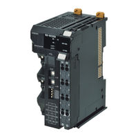
Omron NXEIP202 User Manual (432 pages)
Machine Automation Controller
Brand:
Omron
| Category:
Controller
| Size: 22.85 MB
Table of Contents
Introduction
3
Intended Audience
3
Applicable Products
3
Table of Contents
4
Contents
5
Relevant Manuals
10
Manual Structure
11
Page Structure and Icons
11
Special Information
12
Precaution on Terminology
12
Terms and Conditions Agreement
15
Warranty, Limitations of Liability
15
Application Considerations
16
Disclaimers
16
Safety Precautions
17
Definition of Precautionary Information
17
Symbols
17
Warnings
18
Cautions
19
Precautions for Safe Use
20
Precautions for Correct Use
25
Regulations and Standards
26
Conformance to EU Directives
26
Conformance to UL and CSA Standards
27
Conformance to Shipbuilding Standards
27
Conformance to KC Certification
27
Software Licenses and Copyrights
27
Unit Versions
28
Unit Versions and Support Software Versions
30
Related Manuals
31
Terminology
36
Revision History
38
Sections in this Manual
39
Ethernet/Ip Networks
41
Introduction to Ethernet/Ip
42
Ethernet/Ip Features
42
Ethernet/Ip Network Configuration Elements
45
System Configuration Example of an Ethernet/Ip Network
45
Introduction to Configuration Devices
46
Support Software Used to Construct a Network
47
Features of Ethernet/Ip Slave Terminals
52
System Configurations of Ethernet/Ip Slave Terminals
55
System Configuration
55
Types of NX Units
57
Safety Control System
58
Support Software
59
Applicable Support Software
59
Connection Method and Procedures
59
Specifications
62
General Specifications of Ethernet/Ip Slave Terminals
62
Ethernet/Ip Coupler Unit Specifications
63
End Cover Specifications
66
Procedures
67
Ethernet/Ip Slave Terminal Application Procedures
67
Details
69
Part Names and Functions
71
Parts and Names
72
Ethernet/Ip Coupler Units
72
NX Units
73
End Cover
74
Indicators
75
Hardware Switch Settings
79
Rotary Switches
79
DIP Switch
80
Communications Connector and Peripheral USB Port
81
Terminal Blocks
82
DIN Track Contact Plate
84
Designing the Power Supply System
85
Power Supply System and Design Concepts
86
Power Supply System and Types of Power Supplies
86
NX-Series Power Supply-Related Units
87
Design Concepts for Power Supply to the Ethernet/Ip Slave Terminal
89
Designing the NX Unit Power Supply System
90
Procedure for Designing the NX Unit Power Supply System
90
Calculation Example for the NX Unit Power Supply
91
Designing the I/O Power Supply System
93
I/O Power Supply Method
93
Designing the I/O Power Supply from the NX Bus
94
Designing the I/O Power Supply from External Sources
98
Restrictions on Inrush Current for ON/OFF Operation
98
Selecting External Power Supplies and Protective Devices
100
Selecting the Unit Power Supply
100
Selecting the I/O Power Supplies
102
Selecting Protective Devices
103
Installation
108
Installing Units
108
Installation Precautions
108
Installation Orientation
109
Preparations for Installation
112
Installation Orientation
114
Installing the Ethernet/Ip Coupler Unit
115
Installing and Connecting NX Units
118
Mounting the End Cover
121
Mounting the End Plates
123
Attaching Markers
124
Removing Units
125
Assembled Appearance and Dimensions
127
Control Panel Installation
130
Temperature
130
Humidity
132
Vibration and Shock
132
Atmosphere
132
Electrical Environment
132
Grounding
137
Wiring
139
Ethernet/Ip Network Wiring
140
Installation Precautions
140
Preparations for Installation
140
Pin Arrangement of Communications Connectors on the Ethernet/Ip Coupler Unit
141
Connecting Communications Cables and Connectors
142
Connecting Communications Cables
142
Connecting the Power Supply and Ground Wires
144
Wiring the Ethernet/Ip Coupler Unit
144
Wiring the Power Supply to the Ethernet/Ip Slave Terminal
145
Grounding the Ethernet/Ip Slave Terminal
145
Precautions for Wiring the Ethernet/Ip Slave Terminal Together with Computers and Other Peripheral Devices
149
Wiring to the Screwless Clamping Terminal Block
149
Connecting USB Cable
164
Wiring External Signal Lines
166
Ethernet/Ip Communications
167
Ethernet/Ip Functions
168
Implicit Message Communications
168
Explicit Message Communications
169
Tag Data Links
170
Tag Data Link Data Areas
171
Creating Tag Data Links
173
Setting up Slave Terminals
175
Settings and Setting Procedures
177
Items to Set
177
Slave Terminal Parameters
179
Setting Procedures
179
Setting Slave Terminal Parameters
181
Items to Set
181
Setting the NX Unit Configuration Information
181
I/O Allocation Information
185
I/O Allocation Information
186
Unit Operation Settings
196
Unit Application Data
197
Support Software Functions Used as Required
198
Transferring and Comparing Settings
202
Transferring Slave Terminal Setting Information through the USB Port on the Ethernet/Ip Coupler Unit
202
Comparing Settings
203
Setting IP Address
205
Directly Setting the IP Address with the Network Configurator
205
Getting the IP Address from the BOOTP Server with the Network Configurator
207
Directly Setting the IP Address Using Hardware Switches
208
Getting an IP Address from the BOOTP Server
209
Setting Tag Data Links
210
Starting the Network Configurator
210
Tag Data Link Setting Procedure
212
Registering Devices
213
Determine Tag Sizes
214
Creating Tags and Tag Sets
216
Connection Settings
230
Tag Data Parameters and Specifications
237
Downloading Tag Data Link Parameters
237
Uploading Tag Data Link Parameters
240
Starting and Stopping Tag Data Links
243
Additional Tag Data Link Functions
244
Assigning Network Variables
245
Basic I/O Mapping
245
Support Software I/O Allocation Functions
247
I/O Refreshing
249
Introduction to I/O Refreshing for Ethernet/Ip Slave Terminals
250
Communications Performance
253
I/O Response Time
253
Functions
259
NX Unit Mounting Settings
260
Introduction
260
Applications
261
Setting NX Units as Unmounted Units
262
Event Logs
264
Introduction
264
Detailed Information on Event Logs
265
Automatic Clock Adjustment
267
Reading Event Logs
269
Clearing Event Logs
271
Exporting the Event Log
272
Clearing All Memory
274
Introduction
274
Details on Clearing All Memory
274
Procedure for Clearing All Memory
275
Restarting
279
Introduction
279
Details on Restarting
279
Procedure for Restarting
280
Changing Event Levels
281
Introduction
281
Details on Changing Event Levels
281
Procedure to Change an Event Level
281
Fail-Soft Operation
283
Overview
283
Application
284
Details on Fail-Soft Operation
284
Monitoring Total Power-ON Time
286
Overview
286
Details on Monitoring Total Power-ON Times
286
Checking Total Power-ON Times
286
Ethernet Switch Functions
287
Troubleshooting
289
How to Check for Errors
290
Checking for Errors and Troubleshooting with the Indicators
291
On the Ethernet/Ip Coupler Unit
291
Checking for Errors and Troubleshooting with Support Software
298
Checking Status with the Network Configurator
298
Checking for Errors and Troubleshooting with
298
Connection Status Codes and Troubleshooting
305
Checking for Errors from the Sysmac Studio
309
Checking for Errors from Support Software
309
Other than the Sysmac Studio
309
Event Codes for Errors and Troubleshooting Procedures
310
Resetting Errors
339
Procedure to Reset Errors
339
Troubleshooting Other Errors
342
Maintenance and Inspection
343
Cleaning and Maintenance
344
Cleaning
344
Periodic Inspections
344
Maintenance Procedures
346
Importing and Exporting Data
346
Replacement Procedure for the Ethernet/Ip Coupler Unit
346
Basic Replacement Procedure for NX Units
347
Using Settings from NX Units on Other Slave Terminals
348
Appendices
349
Supported CIP Objects
351
A-1-1 Identity Object (Class ID: 01 Hex
351
Identity Object (Class ID: 01 Hex
351
Assembly Object (Class ID: 04 Hex
353
A-1-3 NX Configuration Object (Class ID: 74 Hex
354
A-1-4 TCP/IP Interface Object (Class ID: F5 Hex
370
Ethernet Link Object (Class ID: F6 Hex
373
A-1-6 Clear Error Explicit Message Example Using CMND(490
375
Response Codes
378
TCP/UDP Message Service
382
A-2-1 System Configuration for Using the TCP/UDP Message Service
382
System Configuration for Using the TCP/UDP Message Service
382
A-2-2 Setup Procedure for TCP/UDP Message Service
384
A-2-5 TCP/IP and UDP/IP Port Number Setting
384
Detailed Setup Procedure for TCP/UDP Message Service
385
TCP/UDP Message Service Specifications
386
A-2-5 TCP/IP and UDP/IP Port Number Setting
389
A-2-6 Troubleshooting Errors Related to the TCP/UDP Message Service
391
Examples of Ethernet/Ip Slave Terminal Settings and I/O Data Control Procedure Using Messages
393
A-3-1 Changing the Unit Operation Settings for the Ethernet/Ip Coupler Unit
394
A-3-2 Changing the Unit Operation Settings of One NX Unit
394
A-3-3 Changing the Unit Operation Settings of Multiple NX Units
395
A-3-4 Changing the Unit Operation Settings of the Entire Ethernet/Ip Slave Terminal
395
Changing the Unit Operation Settings of the Entire Ethernet/Ip Slave Terminal
395
A-3-5 Initializing the Unit Operation Settings of One NX Unit
397
A-3-6 Reading and Writing I/O Data for Ethernet/Ip Slave Terminals
397
Programming Example to Detect Valid I/O Data
399
Application Procedure for the Default Settings
400
A-5-1 Basic Procedure
400
Basic Procedure
400
Connecting to Masters from Other Manufacturers
402
A-6-1 System Configuration
402
System Configuration
402
A-6-2 Application Procedure
403
Dimensions
404
A-7-1 Ethernet/Ip Coupler Unit
404
Ethernet/Ip Coupler Unit
404
A-7-2 End Cover
405
End Cover
405
NX Objects
406
A-8-1 NX Objects
406
A-8-2 Format of Object Descriptions
406
Format of Object Descriptions
406
A-8-3 Unit Information Objects
407
A-8-5 Other Objects
412
Other Objects
412
Terminal Block Model Numbers
413
A-9-1 Model Number Notation
413
Models
413
A-9-2 Models
413
Version Information
415
A-10-1 Relationship between Unit Versions
415
A-10-2 Functions that Were Added or Changed for each Unit Version
418
Advertisement
Advertisement
Related Products
Omron NX-EIP201
Omron NX-ECC201
Omron NX-EC0112
Omron NX-EC0122
Omron NX-EC0132
Omron NX-EC0142
Omron NX-EC0212
Omron NX-EC0222
Omron NX-ECS112
Omron NX-ECS212
Omron Categories
Blood Pressure Monitor
Controller
Accessories
Switch
Inverter
More Omron Manuals
Login
Sign In
OR
Sign in with Facebook
Sign in with Google
Upload manual
Upload from disk
Upload from URL