Table of Contents
Advertisement
Quick Links
Advertisement
Table of Contents
Troubleshooting

Related Manuals for Ruijie RG-RSR10-02E Series


Summary of Contents for Ruijie RG-RSR10-02E Series
- Page 1 RG-RSR10-02E Series Routers Hardware Installation and Reference Guide 1.20...
-
Page 2: Copyright Statement
Ruijie Networks reserves all copyrights of this document. Any reproduction, excerption, backup, modification, transmission, translation or commercial use of this document or any portion of this document, in any form or by any means, without the prior written consent of Ruijie Networks is prohibited. are registered trademarks of Ruijie Networks. -
Page 3: Obtaining Technical Assistance
It is intended for the users who have some experience in installing and maintaining network hardware. At the same time, it is assumed that the users are already familiar with the related terms and concepts. Obtaining Technical Assistance http://www.ruijienetworks.com/ Ruijie Networks website: http://webchat.ruijie.com.cn Online customer services: ... -
Page 4: Chapter 1 Product Overview
The RSR10-02E modular router is an enterprise-class networking product integrating a high-performance 32-bit Reduced Instruction Set Computing (RISC) microprocessor. The router is based on Ruijie RGOS operating system that provides an industry-standard command line interface. The router integrates routing, switching, voice, security, transmission and video, and satisfies personalized requirements in various application environments. -
Page 5: Technical Specifications
For your convenience, each slot is marked with the supported SIC types. For example, in Figure 1-1, SIC SLOT 3 supports Type A, Type B, Type C, and Type E SIC cards. SIC SLOT 2 supports Type A, Type B, Type C and Type E SIC cards. -
Page 6: Product Features
Power Consumption Less than 25 W Operating 0°C to 45°C Temperature Storage Temperature -40°C to 70°C Operating Humidity 10% to 95% RH Dimensions 288 mm x 44 mm x 204 mm (W x H x D) Product Features Access density and processing capacity The two SIC slots support up to 2 non-channelized E1 interfaces, 2 ISDN U or S/T interfaces, 2 synchronous serial interfaces, or 16 asynchronous serial interfaces, 2 3G networks to provide a high-density solution for remote office. -
Page 7: Led Indicators
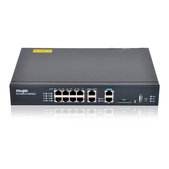
10: FUN button 3: GE0/0 to GE0/1 port 11: PWR indicator, SYS indicator, USB indicator 4: GE0/0 to GE0/1 port indicator 12: Ruijie Networks RSR10 Series logo 5: Console port 6: Aux ports 7: SD card interface 8: SD indicator... -
Page 8: Back Panel
No link. Solid green GE port link up at 1000 Mbps GE Port Blinking green GE port link up at 1000 Mbps, and is receiving or transmitting data. Solid yellow GE port link up at 10/100 Mbps. Blinking yellow GE port link up at 10/100 Mbps, and is receiving or transmitting data. Back Panel Figure 1-4 Back Panel of the RSR10-02E Router Note:... - Page 9 and 115200 bps. The default is 9600 bps. Table 1-6 Specifications of the AUX port Index Parameter Interface Standard EIA/TIA-RS232 Connector RJ-45 Supports 9600 to 115200 bps baud rates. The configurable frequency points are 9600, Rate 19200, 38400, 57600 and 115200 bps. The default is 9600 bps. Cables Serial cables are supplied with the RSR10-02E router.
- Page 10 Crossover cable: Pin 1 and pin 2 at one end of the cable correspond to pin 3 and pin 6 at the other end, respectively. The crossover cable is used to connect two terminal devices, such as connecting a PC to a PC, and connecting a router to a router.
-
Page 11: Port Image And Led Indicators
Table 1-8 Crossover Cable Pinouts RJ45 Pin # RJ45 Pin # Signal Color Signal Color End 1 End 2 White-green White-orange Green Orange White-orange White-green Orange Green GE Ports Port Image and LED Indicators The following figure shows the fixed GE ports and its corresponding Link/ACT LED indicators. Figure 1-9 GE Ports and Corresponding LED Indicators For descriptions of GE port Link/ACT LED indicators, see the “LED Indicators”... - Page 12 Crossover cable: Pin 1 and pin 2 at one end of the cable correspond to pin 3 and pin 6 at the other end, respectively. The crossover cable is used to connect two terminal devices, such as connecting a PC to a PC, and connecting a router to a router.
-
Page 13: Sd Card Slot
USB Port LED Indicator For descriptions of USB port indicator, see the “LED Indicators” section. Features The RSR10-02E series router provides one fixed USB port, through which the user can read configurations from the USB device, or save configurations to the USB device. Table 1-10 Specifications of the USB Port Index Parameters... -
Page 14: Func Button
1.5 Mbps Interface Type Device SD Card Ruijie Networks SDHC card/ Kingston/ 4GB/ class_4 Hot Swapping Supported The hot swapping for the SD device must strictly follow the “Configuring Reliability” chapter in the related software configuration guide. For the avoidance of system abnormality, hot swapping is not allowed unless the command for unplugging the SD card is entered. -
Page 15: About Sic Cards
When an SD card or a USB flash disk is inserted into the device, press the FUNC button. Then, the system searches for the installation packages and configuration files that are applicable to the current device in the root directories of the SD card and USB flash disk in sequence. - Page 16 Features The following table describes basic features of high-speed synchronous serial interface (HS): Table 1-13 Specifications of the SIC-1HS Card Protocol V.24 and V.35 are supported with cable automatic identification. Rate The synchronous port of a single-synchronous card supports from 9600 to 8192000 bps. There are two LED indicators.
-
Page 17: Isdn Interface Card
V.35 DTE One end of this cable is the DB34 male connector, and the other end is the DB26 male connector. Figure 1-17 V.35 DTE cable V.35 DCE One end of this cable is the DB34 female connector, and the other end is the DB26 male connector. Figure 1-18 V.35 DCE cable V.35 DTE-V.35 DCE Both ends of this cable are DB26 male connectors. -
Page 18: Images And Indicators
1-port ISDN U-interface card (SIC-1B-U) 1-port ISDN S/T interface card (SIC-1B-S/T) Images and Indicators The following figure shows the image of the 1-port ISDN U-interface card (SIC-1B-U). Figure 1-20 ISDN-1B-U The SIC-1B-U is a Type A SIC, which can be inserted in a slot marked with “A”. The following figure shows the image of the 1-port ISDN S/T U-interface card (SIC-1B-S/T). -
Page 19: Sic-1E1- F Interface Card
Features The following table describes the basic features: Table 1-15 Specifications of the SIC-1B-U Card Number of Ports Interface Type RJ-45 port (compatible with RJ-11) Telephone cable Cables Standard Compliance ITU-T I.430,Q.921,Q.931 Operating temperature: 0°C to 45°C Temperature: Storage temperature: -40°C to 70°C Humidity Operating humidity: 10% to 90% RH EMI: GB 9254-2008 Class A... - Page 20 The SIC-1E1-F is a Type C line card, which can be inserted in a slot marked with “C”. The following table describes panel indicators. Table 1-17 LED Indicators on the SIC-1E1-F Card Indicator Status Meaning Solid on Upper link has been established. Link Failed to establish the upper link.
- Page 21 Considering that you may customize cables, the following section describes connection modes and the signal. Table 1-19 Signals of the DB9 Male to RJ-45 Plug Cable DB9M RJ-45 Plug Signal RX Ring RX Tip TX Tip TX Ring Balanced cable with the RJ-45 jack One end is the DB9 male connector, and the other end is the RJ-45 jack.
-
Page 22: Sic-8A Interface Card
The cables are customer supplied. For the use of cables, see Chapter 6. SIC-8A Interface Card SIC card model: SIC-8A Image and Indicators The following figure shows the image of an 8-port asynchronous interface card. Figure 1-26 SIC-8A The SIC-8A is a Type A SIC, which can be inserted in a slot marked with “A” The interface card includes one SCSI DB68 connector and eight asynchronous interfaces. - Page 23 STAR-C08A asynchronous card SCSI interface cables with RJ-45 plugs or Cables STAR-C08A asynchronous card SCSI interface cables with RJ-45 jacks Each asynchronous serial interface supports 9600, 19200, 38400, 57600, and 115200 bps Rate baud rates. Flow Control Each asynchronous serial interface supports auto flow control of hardware and software. Operating Operating temperature: 0°C to 45°C Storage temperature: -40°C to 70°C...
- Page 24 Iron shell Iron shell The signal definition of the RJ-45 plug or the RJ-45 female socket attached by the converter cable is for the routers. Asynchronous cable with 1 DB68 male connector to 8 RJ-45 jacks One end is a DB68 male connector, and the other end is attached with eight RJ-45 jacks. Figure 1-28 Asynchronous Cable with 1 DB68 Male Connector to 8 RJ-45 Jacks For the cable pinout, please see Table 1-24.
-
Page 25: Sic-2Fxs Interface Card
RJ-45 jack to DB9 female connector converter Figure 1-31 RJ-45 Jack to DB9 Female Connector Converter The cables are customer supplied. For the use of cables, see Chapter 6. SIC-2FXS Interface Card SIC card model: SIC-2FXS Image and Indicators The following figure shows the image of an SIC-2FXS interface card. Figure 1-32 SIC-2FXS The SIC-2FXS is a Type A SIC, which can be inserted in a slot marked with “A”. -
Page 26: Sic-2Fxo Interface Card
Indicator Status Meaning Initialization failed. Features The following table describes the basic features: Table 1-25 Specifications of the SIC-2FXS Card Number of Ports Interface Type RJ-45 connector (compatible with RJ-11) Cables Telephone cables Standard Compliance Voice code: G.711, G.729A, and G.723.1 Operating temperature: 0°C to 45°C Operating Temperature: Storage temperature: -40°C to 70°C... -
Page 27: Sic-1Ce1 Interface Card
Indicator Status Meaning Solid on The port is active. IN USE The port is idle. Initialization completed. Initialization failed. Features The following table describes the basic features: Table 1-27 Specifications of the SIC-2FXO Card Number of Ports Interface Type RJ-45 connector (compatible with RJ-11) Cables Telephone cables Standard Compliance... - Page 28 The characteristic impedance of the cable is 75Ω. The cables are customer supplied. SIC-SEC SIC card model: SIC-SEC Image and Indicators The following figure shows the image of a Ruijie IPSec SIC with the key encryption function. Figure 1-35 SIC-SEC...
-
Page 29: Sic-3G-Td Interface Card
The following table describes panel indicators. Table 1-30 LED Indicator on the SIC-SEC Card Indicator Status Meaning Initialization completed. Initialization failed. Features The following table describes the basic features: Table 1-31 Specifications of the SIC-SEC Card None Number of Ports Interface Type. -
Page 30: Sic-3G-Cdma-E Interface Card
The following table describes panel indicators. Table 1-32 LED Indicators on the SIC-3G-TD Card Indicator Status Meaning Solid green Link up WWAN (network status) Blinking green Data is being transmitted. Solid green Strong signal RSSI Blinking green Intermediate or low signal Signal is weak or not present Solid green Effective HSDPA service... - Page 31 Image and Indicators The following figure shows the image of SIC-3G-CDMA. Figure 1-37 SIC-3G-CDMA The SIC-3G-CDMA is a Type B SIC module, which can be inserted in a slot marked with “B”. The following table describes panel indicators. Table 1-34 LED Indicators on the SIC-3G-CDMA Card Indicator Status Meaning...
-
Page 32: Sic-3G-Wcdma Interface Card
EMS: GB/T 17618-1998 SIC-3G-WCDMA Interface Card SIC card model: SIC-3G-WCDMA Image and Indicators The following figure shows the image of SIC-3G-WCDMA. Figure 1-38 SIC-3G-WCDMA The SIC-3G-WCDMA is a Type B module, which can be inserted in a slot marked with “B”. The following table describes panel indicators. - Page 33 EDGE (downlink 236.8 Kbps; uplink 236.8 Kbps ) GPRS (downlink 85.6 Kbps; uplink 85.6 Kbps ) Operating temperature: 0°C to 45°C Operating Temperature: Storage temperature: -40°C to 70°C Humidity Operating humidity: 10% to 90% RH EMI: GB 9254-2008 Class A EMS: GB/T 17618-1998 SIC-3G-CDMA-E Interface Card SIC card model: SIC-3G-CDMA-E...
-
Page 34: Sic-3G-Wcdma-E Interface Card
Features The following table describes the basic features: Table 1-39 Specification of the SIC-3G-CDMA-E Card Number of Ports Interface Type RJ-45 Serial cables Cables 1x EV-DO Rev.A (downlink 3.1 Mbps; uplink 1.8 Mbps ) 1x EV-DO Rev.0 (downlink 2.4 Mbps; uplink 153.6 Kbps ) Rate 1x RTT (downlink 153.6 Kbps;... -
Page 35: Sic-3G-Wcdma-H-E Interface Card
Indicator Status Meaning Signal is weak or not present Solid green Effective HSDPA service HSDPA No HSDPA service Solid green Effective UMTS service UMTS No UMTS service Initialization completed. Initialization failed. Features The following table describes the basic features: Table 1-41 Specification of the SIC-3G-WCDMA-E Card Number of Ports Interface Type Cables... -
Page 36: Other Sic Cards
The SIC-3G-WCDMA-H-E is a Type E line card, which can be inserted in a slot marked with “E”. The following table describes panel indicators. Table 1-42 LED Indicators on the SIC-3G-WCDMA-H-E Card Indicator Status Meaning Solid green Link up WWAN (network status) Blinking green Data is being transmitted. - Page 37 Features of RSR10-02E Series Routers For software functions, see the supporting software description. Supporting Multiple Protocols Applicable to various network environments. Providing RJ-45 interfaces for twisted pairs, supporting Ethernet, ARP, and 802.1Q protocols. Supporting various WAN protocols, including X.25, frame relay, HDLC, PPP, and SLIP. ...
-
Page 38: Superior Security
Supporting login through terminals. Supporting configuration over the Console port Supporting login and configuration over telnet. Supporting login and configuration over the serial port. Supporting login and configuration over remote dial-up. Superior Security Using perfect firewall and IP packet filtering technology to enforce strict check on network addresses, port numbers, or protocol types. -
Page 39: Chapter 2 Preparing For Installation
Risk of Explosion if battery is replaced by an incorrect type. Dispose or used batteries according to the instructions. Installation Environment Requirements Ruijie routers are intended for indoor use. For their normal operation and maximum service life, they must be installed at locations that meet the following requirements: ... -
Page 40: Cleanness Requirements
Electrostatic absorption of dust occurs more easily when the relative humidity is low, which may shorten the useful life of the device and cause communication failures. The following table describes Ruijie routers' requirements for the dust content and granularity in the equipment room: Maximum diameter (μm) Maximum concentration 1.4 ×... -
Page 41: Anti-Interference Requirements
Sufficient spacing is reserved at the air inlets and outlets of the routers for good heat dissipation of the routers. Ruijie Networks Routers come with cooling fans, and the cooling principle is like: Cool air is drawn in through the ventilation holes at the four sides of the chassis, and then dissipated through the fans at the bottom of the chassis. -
Page 42: Installation Tools
Ethernet cable Module interface cable The power cables and the configuration cables are provided along with Ruijie RSR10-02E series router delivery, but the Ethernet cables and module interface cables are customer supplied. Related devices include: HUB or switch ... -
Page 43: Chapter 3 Installing The Router
Chapter 3 Installing the Router Installation Flowchart The following is the flowchart of installing a Ruijie series router. Follow the process to ensure a smooth installation and avoid any damage to the router. Fastening the Router Fastening a router refers to the process of mounting a router to the specified location, which occurs after the installation preparation is complete. -
Page 44: Mounting On The Cabinet
Mounting on the Cabinet The Ruijie Networks RSR series router is designed with the 19-inch standard cabinet. Use the supplied fixing accessory for installation when needed. RSR10-02E can be mounted on the cabinet using the shipped sunk screw and fixing accessories. The following figure shows how to install the RSR10-02 on the rack. -
Page 45: Mounting On The Workbench
Insert the anchors into the holes, and fasten the anchors with screws. Align the two mounting holes on the bottom of the device over the screws. Mount the device on the wall. Installing the Power Cable and the Grounding Cable Ruijie RSR10-02E series routers support the following AC power supply:... -
Page 46: Connecting The Console
Disconnect all pluggable communication networks ends and power distribution system ends before disconnecting the power cables. Connecting the Console Ruijie series routers supply an EIA/TIA-232 configuration console for local configuration. This interface enables user to complete the local configuration of the routers. The following table describes the configuration attributes. -
Page 47: Removing Line Cards
Face the router rear panel, and remove the blank panel with screwdrivers. Flush the line card interface board and the edge of the opening of the back panel of the router base. Push the line card to the router until the interface board closely touches the backplane of the router. Tighten the fastening screws on the line card. - Page 48 Verify whether the power supply meets the requirements. Verify whether the grounding cable is correctly connected. Verify whether the router is connected correctly to other devices like the configuration terminal.
-
Page 49: Chapter 4 Starting And Configuring The Router
Chapter 4 Starting and Configuring the Router Starting a Router Setting Up the Configuration Environment When you use the router for the first time, you must configure the router over a console port as follows. As shown in the following figure, connect the serial port of a character terminal or PC to the Console port of the network output engine through the standard RS232 cable and the Console. -
Page 50: Startup Process
Ruijie General Operating System Software Release Software (tm), RGOS 10.3(4), Release(53498), Compiled Fri Apr 3 08:45:59 CST 2009 by ngcf31 Copyright (c) 1998-2009 by Ruijie Networks. All Rights Reserved. Decompiling or Reverse Engineering is Not Allowed. 00:00:00:00: %MTD_DRIVER-5-MTD_NAND_FOUND: 1 NAND chips(chip size : 33554432) detected 00:00:00:00: %MTD_DRIVER-5-MTD_NAND_FOUND: 1 nand chip(s) found on the target. -
Page 51: Configuring The Router
When using the router for the first time, it is recommended you set basic parameters using the configuration function. Configuring the Router You need to configure a router before using it. For more information about router configuration, see the related Configuration Guide and Command Reference. -
Page 52: Chapter 5 Troubleshooting
Chapter 5 Troubleshooting Power Troubleshooting For the RSR10-02E series, you can determine whether the power system has faults by the PWR indicator on the front panel. For the normal status of the indicator, see the description in Chapter 1. If exceptions occur, verify the following: ... -
Page 53: Chapter 6 Using The Cables
Chapter 6 Using the Cables This chapter describes the use of various cables and converters when applying routers. Physical Cable Connection Connecting an Asynchronous Interface Connecting an Asynchronous Interface Module to a Modem As a DCE device, the modem has two types of serial interfaces: DB9F and DB25F female sockets. Connecting the Asynchronous Card to the Modem The asynchronous cable with 1-to-8 crystal connectors converts the 68-pin connector of the asynchronous interface into eight RJ-45 connectors, and then connects to the DB25F interface of the modem through the RJ-45 (crystal jack)-DB25... -
Page 54: Connecting An Asynchronous Interface Module To A Terminal
Device Device Device Peer RJ-45(crystal jack)-DB25 AUX port Rollover cable DB25F interface of the Modem male converter Connecting an Asynchronous Interface Module to a Terminal The asynchronous cable with 1-to-8 crystal connectors converts the 68-pin connector of the asynchronous interface into eight RJ-45 connectors, and connects to the DB9M interface of a terminal (for instance, dumb terminal) through the RJ-45 (crystal jack)-DB9 female converter. -
Page 55: Connecting The E1 Interface
Peer CONSOLE interface DB9F-to-RJ45 cable PC’s DB9M serial interface Ordering Information Ruijie Networks provides all previously mentioned cables, except for modem cables shown in the following table are provided by the modem manufacturer. Table: Cable ordering information Number Model Name... - Page 56 V-03260025-000 CAB-V.35DTE/POS26-34PM/3M V.35DTE cable V-03260028-000 CAB-V.35DCE/POS26-34PF/3M V.35DCE cable V-03260024-000 CAB-V.35DTE-V.35DCE/POS26-POS26/1M V.35DTE-V.35DCEc able V-03260030-000 CAB-V.24DTE/POS26-DB25M/3M V.24DTE cable V-03260031-000 CAB-V.24DCE/POS26-DB25F/3M V.24DCE cable Asynchronous cable (1 to 8 crystal V-03260032-000 CAB-Asy/SCSIDB68-8*RJ45M/1.5m connector) V-03260047-000 CAB-Asy/SCSIDB68-8*RJ45F/1.5m Asynchronous cable (1 to 8 crystal jack) V-03260034-000 CAB-Rolled/RJ45M-RJ45M/3m Rollover cable V-03260060-000 ADAPTER/RJ45F-DB9F...
Need help?
Do you have a question about the RG-RSR10-02E Series and is the answer not in the manual?
Questions and answers