
Related Manuals for Ruijie RG-RSR20-XA Series


Summary of Contents for Ruijie RG-RSR20-XA Series
- Page 1 RG-RSR20-XA Series Routers Hardware Installation and Reference Guide Document Version: V1.3 Date: 2022-10-31 Copyright © 2023 Ruijie Networks...
- Page 2 All rights are reserved in this document and this statement. Any reproduction, excerption, backup, modification, transmission, translation or commercial use of this document or any portion of this document, in any form or by any means, without the prior written consent of Ruijie Networks is prohibited.
-
Page 3: Preface
Preface Intended Audience This document is intended for: Network engineers Technical support and service engineers Network administrators Technical Support Ruijie Networks website: https://www.ruijienetworks.com/ Technical support website: https://ruijienetworks.com/support Case portal: https://caseportal.ruijienetworks.com Community: https://community.ruijienetworks.com ... - Page 4 Warning An alert that calls attention to important rules and information that if not understood or followed can result in data loss or equipment damage. Caution An alert that calls attention to essential information that if not understood or followed can result in function failure or performance degradation.
-
Page 5: Table Of Contents
Contents Preface ..............................I 1 Product Overview ..........................1 1.1 Introduction to RG-RSR20-XA Series ..................1 1.2 RG-RSR20-XA-24........................1 1.2.1 Package Contents ......................1 1.2.2 Product Appearance ...................... 2 1.2.3 Technical Specifications ....................6 1.3 RG-RSR20-XA-36........................8 1.3.1 Package Contents ......................8 1.3.2 Product Appearance ...................... - Page 6 1.7.2 10GE Optical Modules ....................28 1.8 Cables ............................29 1.8.1 Console Port Cables ....................29 1.8.2 Ethernet Port Cables ....................29 1.8.3 Optical Fibers ....................... 29 1.8.4 E1 Cables ........................30 1.8.5 Antenna ........................32 2 Preparing for Installation ........................34 2.1 Safety Precautions ........................
- Page 7 2.2.9 Others .......................... 38 2.3 Cabinet Installation Requirements ................... 39 2.4 Tools ............................40 3 Installing the Device ......................... 40 3.1 Installation Procedure ......................41 3.2 Installation Preparation ......................41 3.3 Fixing the Device Location....................... 42 3.3.1 Installing the Device in a Cabinet ................42 3.3.2 Installing the Device on a Workbench .................
- Page 8 4.2.3 Checklist After Power-on ..................... 48 5 Monitoring and Maintenance ......................49 5.1 Monitoring Devices Through CLI Commands ................. 49 5.2 Hardware Maintenance ......................49 5.2.1 Line Cards ........................49 5.2.2 Power Modules ......................49 5.2.3 Expansion Modules ...................... 49 5.2.4 Heat Dissipation System ....................
-
Page 9: Product Overview
It supports the Border Gateway Protocol (BGP), IP multicast protocols, and rich QoS features, provides power modules in redundancy mode, and allows users to configure optional modules. They can function as access layer routers on large-scale industry networks. The RG-RSR20-XA series routers come into the RG-RSR20-XA-24, RG-RSR20- XA-36, and RG-RSR20-XA-54. -
Page 10: Product Appearance
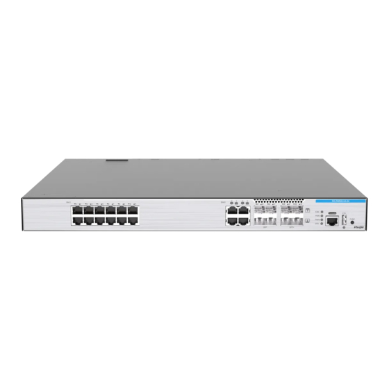
Hardware Installation and Reference Guide 1.2.2 Product Appearance 1. Front Panel Figure 1-1 Front Panel Table 1-2 Ports, LEDs, and Buttons on the Front Panel Item Description Solid yellow: A link is set up on the port at a rate of 10/100 Mbps. LED of the Blinking yellow: A link is set up on the port at a rate of 10/100 Mbps and data is transmitted on the link. - Page 11 Hardware Installation and Reference Guide Item Description Solid green: A link is set up on the port. Blinking green: A link is set up on the port and data is transmitted SFP+ optical port LED on the link. Off: No link is set up on the port. For more information about applicable optical modules, see Pluggable SFP+ optical port...
- Page 12 Hardware Installation and Reference Guide Figure 1-2 Location of the Nameplate 2. Rear Panel Figure 1-3 Rear Panel...
- Page 13 Hardware Installation and Reference Guide Table 1-3 Description of the Rear Panel Module Slot and Grounding Description Stud Slot 2 HSIC service module slot 2 Slot 4 HSIC service module slot 4 Slot 5 HSIC service module slot 5 Grounding stud Protection against lightning strikes and interference Power module slot 0: Install the power module first and then connect the AC power cord.
-
Page 14: Technical Specifications
Hardware Installation and Reference Guide 1.2.3 Technical Specifications Table 1-4 Technical Specifications of the RG-RSR20-XA-24... - Page 15 Hardware Installation and Reference Guide Model RG-RSR20-XA-24 4GB DDR4 Flash Memory 8GB eMMC 10/100/1000Base-T – Ethernet Port in Auto- 12 (1/0 1/11) Negotiation Mode Layer 3 10/100/1000Base- – T Ethernet Port in Auto- 4 (0/0 0/3) negotiation Mode – SFP+ Optical Port 4 (8F 11F) –...
-
Page 16: Rg-Rsr20-Xa-36
Chassis Fixed bracket Footbed Fixed bracket installation instruction Warranty card and list of hazardous substances M4X8 Phillips countersunk screw GB819- Yellow/Green ground cable Access device management software of Ruijie Networks Note The product management software is pre-installed in the device. -
Page 17: Product Appearance
Hardware Installation and Reference Guide 1.3.2 Product Appearance 1. Front Panel Figure 1-4 Front Panel Table 1-6 Ports, LEDs, and Buttons on the Front Panel Item Description Solid yellow: A link is set up on the port at a rate of 10/100 Mbps. LED of the Blinking yellow: A link is set up on the port at a rate of 10/100 Mbps and data is transmitted on the link. - Page 18 Hardware Installation and Reference Guide Item Description Solid green: A link is set up on the port. Blinking green: A link is set up on the port and data is transmitted SFP+ optical port LED on the link. Off: No link is set up on the port. For more information on applicable optical modules, see Pluggable SFP+ optical port...
- Page 19 Hardware Installation and Reference Guide Figure 1-5 Location of the Nameplate 2. Rear Panel Figure 1-6 Rear Panel...
- Page 20 Hardware Installation and Reference Guide Table 1-7 Description of the Rear Panel Module Slot and Grounding Description Stud Slot 2 HSIC service module slot 2 Slot 4 HSIC service module slot 4 Slot 5 HSIC service module slot 5 Grounding stud Protection against lightning strikes and interference Power module slot 0: Install the power module first and then connect the AC power cord.
-
Page 21: Technical Specifications
Hardware Installation and Reference Guide 1.3.3 Technical Specifications Table 1-8 Technical Specifications of the RG-RSR20-XA-36... - Page 22 Hardware Installation and Reference Guide Model RG-RSR20-XA-36 Memory 4 GB DDR4 FLASH 8 GB eMMC 10/100/1000Base-T – Ethernet Port in Auto- 24 (1/0 1/23) Negotiation Mode Layer 3 10/100/1000Base- – T Ethernet Port in Auto- 4 (0/0 0/3) negotiation Mode –...
-
Page 23: Rg-Rsr20-Xa-54
Chassis Fixed bracket Footbed Fixed bracket installation instruction Warranty card and list of hazardous substances M4X8 Phillips countersunk screw GB819- Yellow/Green ground cable Access device management software of Ruijie Networks Note The product management software is pre-installed in the device. -
Page 24: Product Appearance
Hardware Installation and Reference Guide 1.4.2 Product Appearance 1. Front Panel Figure 1-7 Front Panel Table 1-10 Ports, LEDs, and Buttons on the Front Panel Item Description Solid yellow: A link is set up on the port at a rate of 10/100 Mbps. LED of the Blinking yellow: A link is set up on the port at a rate of 10/100 Mbps and data is transmitted on the link. - Page 25 Hardware Installation and Reference Guide Item Description After the FUNC button is pressed, the system will reset and restart FUNC button according to the original software version. Solid green: The USB flash drive works properly. USB port LED Solid red: The USB flash drive encounters an exception. Off: The USB flash drive is not installed.
- Page 26 Hardware Installation and Reference Guide Figure 1-8 Location of the Nameplate 2. Rear Panel Figure 1-9 Rear Panel...
- Page 27 Hardware Installation and Reference Guide Table 1-11 Description of the Rear Panel Module Slot and Grounding Description Stud Slot 2 HSIC service module slot 2 Slot 4 HSIC service module slot 4 Slot 5 HSIC service module slot 5 Grounding stud Protection against lightning strikes and interference Power module slot 0: Install the power module first and then connect the AC power cord.
-
Page 28: Technical Specifications
Hardware Installation and Reference Guide 1.4.3 Technical Specifications Table 1-12 Technical Specifications of the RG-RSR20-XA-54... - Page 29 Hardware Installation and Reference Guide Model RG-RSR20-XA-54 Memory 4 GB DDR4 Flash 8 GB eMMC 10/100/1000Base-T – Ethernet Port in Auto- 48 (1/0 1/47) Negotiation Mode Layer 3 10/100/1000Base- – T Ethernet Port in Auto- 4 (0/0 0/3) negotiation Mode –...
-
Page 30: Rg-Pa150Ib-F Power Module
Hardware Installation and Reference Guide Warning In a domestic environment, this product may cause radio interference in which case the user may be required to take adequate measures. RG-PA150IB-F Power Module 1.5.1 Module Appearance Figure 1-10 Appearance of the RG-PA150IB-F Power Module Table 1-13 LED of the RG-PA150IB-F Power Module Description... -
Page 31: Service Modules
Hardware Installation and Reference Guide Hot Swapping of the Supported Power Module Power Module 1+1 redundancy Redundancy Overvoltage Protection Supported Overcurrent Protection Supported Power Cord 10 A power cord Dimensions (W x D x H) 51 mm x 196 mm x 40 mm (2.01 in. x 7.72 in. x 1.57 in.) Operating temperature: 0º... - Page 32 Hardware Installation and Reference Guide Table 1-15 Description of LEDs and Button of the HSIC-2E1/CE1 Service Module Description Function module status LED: Blinking green: The module is being initialized. Solid green: Initialization is complete, and the module works properly. Off: The module is not powered on, is not installed properly, or is removed.
-
Page 33: Hsic-4G-Lte Service Module
Hardware Installation and Reference Guide 3. Cables You can choose to configure crystal head balanced cables, crystal hole interface balanced cables, and unbalanced cables. For more information about cable types, see Cables. 1.6.2 HSIC-4G-LTE Service Module Module Appearance Figure 1-12 Appearance of the HSIC-4G-LTE Service Module Table 1-17 Description of LEDs of the HSIC-4G-LTE Service Module... -
Page 34: Pluggable Modules
Hardware Installation and Reference Guide 2. Technical Specifications Table 1-18 Technical Specifications of the HSIC-4G-LTE Service Module Number of One 4G port Ports Connector Two SMA-J connectors for connecting dual antennas Type Cable 4G antenna Supported All bands Rate Operating temperature: 0º C to 50º C (32º F to 122º F) Temperature Storage temperature: –40º... -
Page 35: Ge Optical Modules
Hardware Installation and Reference Guide 1.7.1 GE Optical Modules Table 1-19 List of GE SFP Modules Transmit Receive Power Power (dBm) Wavelength Fiber (dBm) Supported (nm) Type (Yes/No) Min. – Multim –3 –17 Mini-GBIC-SX – Single- –3 –20 –3 Mini-GBIC-LX 1310 mode –... -
Page 36: 10Ge Optical Modules
Note SFP+ module types are subject to change without prior notice. For more accurate information about the optical modules, contact Ruijie marketing or technical support personnel. For XG-SFP-ER-SM1550 and XG-SFP-ZR-SM1550 modules, do not use short-distance optical cables for interconnection to avoid overload on the optical receiver of the module. -
Page 37: Cables
Hardware Installation and Reference Guide Cables 1.8.1 Console Port Cables console port cable is the dedicated serial port cable where the DB9 female connector is converted to the RJ45 male connector. You can use this cable to connect the console port of the device to the serial port of a terminal for completing local device configuration. -
Page 38: E1 Cables
Hardware Installation and Reference Guide Max. Connector Core Size (μm) SFP Type Fiber Type Cabling Type Distance Mini-GBIC-ZX50 Single-mode 9/125 50 km Mini-GBIC-ZX80 Single-mode 9/125 80 km Mini-GBIC-ZX100 Single-mode 9/125 100 km Table 1-22 SFP+ Module Cabling Specifications Modular Connector Core Size Max. - Page 39 Hardware Installation and Reference Guide Figure 1-13 Balanced Cable (Standard RJ45 Connector) Table 1-23 Description of Signal Connections of the Balanced Cable (Standard RJ45 Connector) DB9M RJ45 Signal RX Ring RX Tip TX Tip TX Ring Balanced Cable (Pass-through RJ45 Connector) The cable has a DB9 male connector on one end and a pass-through RJ45 connector on the other end.
-
Page 40: Antenna
Hardware Installation and Reference Guide Unbalanced Cable The cable has a DB9 male connector on one end and two BNC male connectors on the other end. The characteristic impedance of the cable is 75 ohm. Figure 1-15 Unbalanced Cable Cables are not delivered and need to be purchased separately or supplied. 1.8.5 Antenna 1. - Page 41 Hardware Installation and Reference Guide 2. Technical Specifications Table 1-25 Technical Specifications of the LTE Suction Iron Antenna Model RG-ANT-2G3G4G3M Description 2G/3G/4G all-band suction iron extension antenna 824–960 MHz Supported Bands 1700–2700 MHz 0.5 dBi@824–960 MHz Maximum Gain 2 dBi@1700–2700 MHz ≤...
-
Page 42: Preparing For Installation
Hardware Installation and Reference Guide Preparing for Installation Safety Precautions Note To avoid personal injury and device damage, carefully read the safety precautions before you install the device. The following safety precautions may not cover all possible dangers. 2.1.1 General Safety Precautions Danger... -
Page 43: Esd
Hardware Installation and Reference Guide ● Replacement of a battery with an incorrect type that can defeat a safeguard (for example,in the case of some lithium battery types). ● Disposal of a battery into fire or a hot oven, or mechanically crushing or cutting of a battery, that can result in an explosion. -
Page 44: Storage
Hardware Installation and Reference Guide When an optical transceiver is working, do not pull out the fiber cable or look directly into the fiber transceiver. The optical module emits laser light that may hurt your eyes. Danger Do not stare into any optical port under any circumstances because this may cause permanent damage to your eyes. -
Page 45: Cleanliness
Hardware Installation and Reference Guide For details about the operating temperature and operating humidity, see Technical Specifications. Note The ambient temperature and humidity of the device are measured at the point that is 1.5 m (59.06 in.) above the floor and 400 mm (15.75 in.) before the device when there is no protective plate in front or at the rear of the device. -
Page 46: Grounding
Hardware Installation and Reference Guide 2.2.6 Grounding A good grounding system is the basis for stable and reliable operation of the device, preventing lightning strokes and resisting interference. Carefully check the grounding conditions at the installation site according to the grounding requirements, and perform grounding operations properly as required. -
Page 47: Cabinet Installation Requirements
Hardware Installation and Reference Guide Maintain a proper clearance around air intakes and outlets for heat dissipation. Maintain a minimum clearance of 150 mm (5.91 in.) around the ventilation openings for heat dissipation. You are advised to install the device in a standard 19-inch rack. Or, place the device on a clean workbench. In hot areas, air-conditioning is recommended. -
Page 48: Tools
Hardware Installation and Reference Guide Tools Table 2-3 Tools Category Description Common tools Phillips screwdriver, power cords, Ethernet cables, cage nuts, diagonal plier, and cable ties Special tools ESD gloves, wire stripper, common crimping plier, RJ45 crimping plier, and wire cutter Meters Multimeter Relevant... -
Page 49: Installation Procedure
Hardware Installation and Reference Guide Installation Procedure Figure 3-1 Installation Procedure Installation Preparation Fixing the Device Location Installing a Power Module Installing Service Modules Verifying Installation Installation Preparation The installation site provides sufficient space for heat dissipation. The installation site meets the temperature and humidity requirements of the device. -
Page 50: Fixing The Device Location
Hardware Installation and Reference Guide The power supply is available in the installation site and meets current requirements. Ethernet cables have been deployed at the installation site. The selected power supply meets requirement for the system power. ... -
Page 51: Installing A Power Module
Hardware Installation and Reference Guide Figure 3-3 Removing the Power Module 3.4.1 Installing a Power Module (1) Remove the filler panel in the slot where the power module needs to be installed. (2) Align the device power module with the opening edge of the power module slot on the rear panel of the device. -
Page 52: Installing Power Cords And Grounding Cables
Hardware Installation and Reference Guide Danger Before removing the device power module, make sure that the power cord of the corresponding power module is not connected to the power outlet of the power module. Otherwise, it may cause electric shock to the operator or damage to the device. -
Page 53: Installing Service Modules
Hardware Installation and Reference Guide Installing Service Modules For a list of supported modules, see Service Modules. Note In this section, the service module is installed without power supply. The hot swapping process is detailed in the software usage document. 3.5.1 Installing a Service Module (1) Align the service module with the opening edge of the service slot on the front panel of the device. -
Page 54: Troubleshooting
Hardware Installation and Reference Guide 3.5.3 Troubleshooting If the installed service module cannot work properly, check the following items: Check whether Ethernet cables of the service module are correctly matched. Observe each module port LED to check whether the service module is working properly. ... -
Page 55: Verifying The Operating Status
Hardware Installation and Reference Guide Verifying the Operating Status Setting Up the Configuration Environment Connect a PC to the console port of the device by using an Ethernet cable. Figure 4-1 Setting Up the Configuration Environment When the device is used for the first time, the device must be configured through the console port: (1) Connect the terminal's serial port to the device's console port (configuration port) through a standard RS232 cable. -
Page 56: Device Power-On
Hardware Installation and Reference Guide Verify that fan modules and power modules are securely seated. Verify that power cords are properly connected. Verify that the power supply voltage meets the requirement of the device. Verify that the Ethernet cable is properly connected, the client (for example, a PC) is started, and configuration parameters are configured. -
Page 57: Monitoring And Maintenance
Hardware Installation and Reference Guide Monitoring and Maintenance Monitoring Devices Through CLI Commands You can run related commands on the CLI of the device to remotely monitor the device status, including: Module or card installation status Port configuration and status ... -
Page 58: Troubleshooting
Hardware Installation and Reference Guide Troubleshooting Configuration System Troubleshooting After the device is powered on, if the configuration system fails, no information is display or garbled characters are displayed on the terminal. If the terminal does not display any information, perform the following check: ... -
Page 59: Appendix
Hardware Installation and Reference Guide Appendix Self-made Cable Connection Modes The connection method and signal description are provided considering self-made cables. Keep the back of the RJ45 locking clip facing yourself. The signal lines are numbered 1 to 8 from left to right. Figure 7-1 Cable Connection Modes and Signals Table 7-1... - Page 60 Hardware Installation and Reference Guide Figure 7-2 1000BASE-T Twisted Pair Connections Table 7-2 100BASE-TX/10BASE-T Pin Assignments MDI Mode MDI-X Mode Output Transmit Data+ Input Receive Data+ Output Transmit Data- Input Receive Data- Input Receive Data+ Output Transmit Data+ Input Receive Data- Output Transmit Data- 4, 5, 7, 8 Not used...
-
Page 61: Labeling Process
Hardware Installation and Reference Guide Labeling Process 7.2.1 Manual Writing of Labels Writing tool: black gel pen 7.2.2 Pasting Labels Fill in the label content on the full-page label paper before attaching the label, and then uncover and paste it on the power cord or signboard wire buckle. -
Page 62: Label Contents
Hardware Installation and Reference Guide Figure 7-5 Steps and Methods for Attaching Signal Line Labels 7.2.3 Label Contents The contents of the two sides of the label identify the location of the ports connected to the two ends of the power cord. -
Page 63: Cabling
Hardware Installation and Reference Guide Cabling When the device is installed in a standard 19-inch cabinet, secure the cables around the cable management brackets. Top or bottom cabling is adopted according to the actual situation in the equipment room. All cable connectors should be placed at the bottom of the cabinet, and cannot be exposed outside the cabinet. - Page 64 Hardware Installation and Reference Guide Route and bundle power, signal, ground cables separately. When the cables are close to each other, cross them. Mixed bundling is not allowed. When they are close to each other, crossover cabling is recommended. In the case of parallel cabling, maintain a minimum distance of 30 mm (1.18 in.) between power cords and signal cables.
- Page 65 Hardware Installation and Reference Guide of the cabinet or cable trough. The proper position refers to a position that does not affect device running or damage the device or cable. 220 V and –48 V power cords must not be bundled on the guide rails of moving parts. ...
-
Page 66: Equipment Room Selection
Hardware Installation and Reference Guide For wiring terminal blocks (such as circuit breakers) with cord end terminals, the metal part of the cord end terminal should not be exposed outside the terminal block when assembled. Equipment Room Selection The equipment room should be at least 5 km away from heavy pollution sources, such as the smelter works, coal mine, and thermal power plant.
Need help?
Do you have a question about the RG-RSR20-XA Series and is the answer not in the manual?
Questions and answers