
Related Manuals for Ruijie RG-RSR77-XA Series


Summary of Contents for Ruijie RG-RSR77-XA Series
- Page 1 RG-RSR77-XA Series Routers Hardware Installation and Reference Guide Document Version: V1.4 Date: 2023.08.28 Copyright © 2023 Ruijie Networks...
- Page 2 Due to product version upgrades or other reasons, the content of this document will be updated from time to time. Ruijie Networks reserves the right to modify the content of the document without any notice or prompt. This manual is for reference only. Ruijie Networks endeavors to ensure content accuracy and will not shoulder any responsibility for losses and damages caused due to content omissions, inaccuracies or errors.
-
Page 3: Preface
Preface Intended Audience This document is intended for: Network engineers Technical support and service engineers Network administrators Technical Support Ruijie Networks website: https://www.ruijienetworks.com/ Technical support website: https://ruijienetworks.com/support Case portal: https://caseportal.ruijienetworks.com Community: https://community.ruijienetworks.com ... - Page 4 Signs The signs used in this document are described as follows: Warning An alert that calls attention to important rules and information that if not understood or followed can result in data loss or equipment damage. Caution An alert that calls attention to essential information that if not understood or followed can result in function failure or performance degradation.
-
Page 5: Table Of Contents
Contents Preface ..............................I 1 Product Overview ..........................1 1.1 Introduction to RG-RSR77-XA Series ..................1 1.2 RG-RSR77-XA-08........................1 1.2.1 Package Contents ......................1 1.2.2 Product Appearance ...................... 2 1.2.3 Technical Specifications ....................7 1.2.4 Power Supply ......................... 9 1.2.5 Heat Dissipation ......................9 1.3 RG-RSR77-XA-03........................ - Page 6 1.6.2 NM-4XS-KB ........................32 1.6.3 NM-2XS-KA ........................34 1.6.4 NM-8GT-G ........................36 1.6.5 NM-8SFP-G ......................... 38 1.6.6 NM-8E1/CE1 ........................ 40 1.6.7 DNM-1CQ-KC ......................44 1.7 Power Modules ........................46 1.7.1 RG-PA1600I Power Module ..................46 1.7.2 RG-PD600I Power Module ..................49 1.7.3 RG-PA460-RI Power Module ..................
- Page 7 2.2.3 Space ........................... 62 2.2.4 Temperature and Humidity ................... 62 2.2.5 Cleanliness ........................63 2.2.6 Grounding ........................64 2.2.7 Anti-interference ......................64 2.2.8 Surge Protection ......................65 2.2.9 Checking Installation Facilities ..................65 2.2.10 EMI ..........................65 2.3 Cabinet Installation Requirements ................... 66 2.4 Tools ............................
- Page 8 3.5.2 Installation Steps ......................75 3.6 System Grounding ........................76 3.6.1 Precautions ........................76 3.6.2 Connecting the System Ground................... 76 3.7 Installing a Power Module ......................78 3.7.1 Installing the RG-RSR77-XA-08 Power Module ............79 3.7.2 Installing the RG-RSR77-XA-03 Power Module ............79 3.8 Installing a Fan Module ......................
- Page 9 4.1.2 Setting Terminal Parameters ..................94 4.2 Powering On the Router ......................96 4.2.1 Checklist Before Power-on ..................96 4.2.2 Checklist After Power-on ..................... 96 5 Monitoring and Maintenance ......................96 5.1 Monitoring ..........................96 5.1.1 LEDs ..........................96 5.1.2 CLI Commands ......................97 6 Troubleshooting ..........................
- Page 10 7.2.2 Removing an SFP+ Electrical Module ............... 104 7.2.3 Replacing a Card ....................... 105 7.2.4 Replacing a Power Module ..................108 7.2.5 Replacing a Fan Module .................... 110 8 Cables ............................113 8.1 Connecting External Port Cables ..................113 8.1.1 Precautions ........................ 113 8.1.2 Steps ..........................
- Page 11 12.1 Requirement for the Minimum Cable Bend Radius ............. 124 12.2 Requirement for the Minimum Bend Radius of an Optical Fiber ......... 124 12.3 Precautions for Cable Bundling ................... 124 13 Appendix E Site Selection ......................129...
-
Page 12: Product Overview
Introduction to RG-RSR77-XA Series The RG-RSR77-XA series router is a next-generation high-end distributed router independently developed by Ruijie Networks. It provides dual supervisor modules and power modules in redundancy mode. The RSR77-XA series modular router is available in RSR77- XA-08 and RSR77-XA-03. -
Page 13: Product Appearance
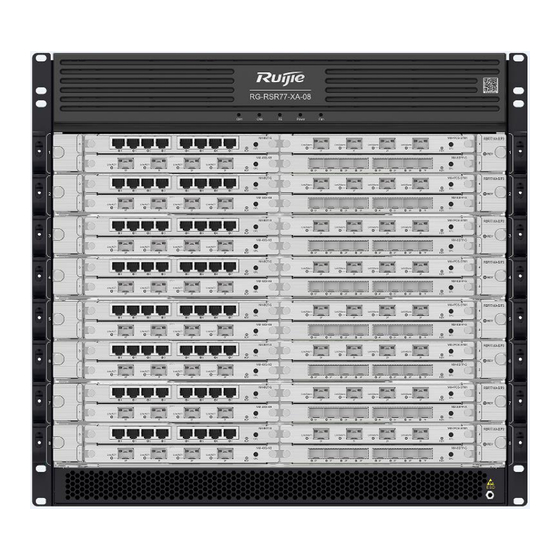
RG-RSR77-XA Series Router Hardware Installation and Reference Guide Product Overview Item Quantity Remarks Form (50 years) Ruijie router product software platform Rack Mounting Guide Note The product management software is pre-installed in the RG-RSR77-XA-08. 1.2.2 Product Appearance 1. Appearance of the RG-RSR77-XA-08... - Page 14 RG-RSR77-XA Series Router Hardware Installation and Reference Guide Product Overview Figure 1-1 Appearance of the RG-RSR77-XA-08 2. Front Panel Figure 1-2 shows the front panel of the RG-RSR77-XA-08; Table 1-2 describes numbers 1 to...
- Page 15 RG-RSR77-XA Series Router Hardware Installation and Reference Guide Product Overview Figure 1-2 Front Panel of the RG-RSR77-XA-08 Table 1-2 Ports, LEDs, and Other Items on the Front Panel Item Description CM1: Off: The module is not powered on. Solid red: An exception occurs in the module.
- Page 16 RG-RSR77-XA Series Router Hardware Installation and Reference Guide Product Overview Blinking green: The supervisor module is being initialized. If the LED blinks green continuously, an exception occurs in the supervisor module. Solid green: Module initialization is complete and the supervisor module works normally.
- Page 17 RG-RSR77-XA Series Router Hardware Installation and Reference Guide Product Overview 3. Rear Panel Figure 1-3 shows the rear panel of the RG-RSR77-XA-08; Table 1-3 describes numbers 1 to Figure 1-3 Rear Panel of the RG-RSR77-XA-08 Table 1-3 Description of the Rear Panel...
-
Page 18: Technical Specifications
RG-RSR77-XA Series Router Hardware Installation and Reference Guide Product Overview Module Slot and Grounding Description Stud Fan module slot It is used for installing a fan module. Grounding stud It is used to connect to the ground cable. 1.2.3 Technical Specifications... - Page 19 RG-RSR77-XA Series Router Hardware Installation and Reference Guide Product Overview Hot Swapping Supported RG-PA1600I: Rated voltage range: 100 V to 240 V AC Max. voltage range and power: 90V to 180V AC, 1200W; 180 V to 264 V AC, 1600 W...
-
Page 20: Power Supply
RG-RSR77-XA Series Router Hardware Installation and Reference Guide Product Overview 442 mm x 606.7 mm x 442.5 mm (17.40 in. x 23.89 in. x 17.42 in., excluding the cable management bracket), 10 RU Dimensions (W x D x H) The depth of the chassis with the cable management bracket is 670.1 mm (26.38 in.) - Page 21 RG-RSR77-XA Series Router Hardware Installation and Reference Guide Product Overview 08 uses fans to draw air for forced convection cooling, ensuring that the device works properly in the specified environment. Figure 1-4 Air Inlet for Heat Dissipation of the RG-RSR77-XA-08...
- Page 22 RG-RSR77-XA Series Router Hardware Installation and Reference Guide Product Overview Figure 1-5 Air Outlet for Heat Dissipation of the RG-RSR77-XA-08 Table 1-6 Description of Air Outlet for Heat Dissipation of the RG-RSR77-XA-08 Description Air outlet for heat dissipation of the system power module...
-
Page 23: Rg-Rsr77-Xa-03
RG-RSR77-XA Series Router Hardware Installation and Reference Guide Product Overview Supervisor module or switch fabric module: adopts bottom-to-rear airflow, with the fan module drawing air backwards to generate convection for heat dissipation. Note When placing the chassis, leave enough space around for air circulation, and maintain a minimum clearance of 10 cm (3.94 in.) around air inlet and outlet. -
Page 24: Product Appearance
RG-RSR77-XA Series Router Hardware Installation and Reference Guide Product Overview Note The product management software is pre-installed in the RG-RSR77-XA-03. 1.3.2 Product Appearance 1. Appearance of the RG-RSR77-XA-03 The RG-RSR77-XA-03 consists of the chassis, power supply system, system modules, and cooling system. - Page 25 RG-RSR77-XA Series Router Hardware Installation and Reference Guide Product Overview Figure 1-7 Front Panel of the RG-RSR77-XA-03 Table 1-8 Description of the Front Panel Item Description Supervisor It is used for installing a supervisor module. module slot Functional It is used for installing a functional module.
-
Page 26: Technical Specifications
RG-RSR77-XA Series Router Hardware Installation and Reference Guide Product Overview Figure 1-8 Rear Panel of the RG-RSR77-XA-03 Table 1-9 Description of the Rear Panel Item Description System power It is used for installing a power module. module slot It is used to connect the ground cable to prevent lightning Grounding screw strikes and interference. - Page 27 RG-RSR77-XA Series Router Hardware Installation and Reference Guide Product Overview The line card slot can have the RSR77-XA-SIP3 carrier card installed, and each carrier card supports up to four NM modules. Model of NM Module Module Name NM-4XS-KB 4-port 10GE optical interface...
-
Page 28: Power Supply
RG-RSR77-XA Series Router Hardware Installation and Reference Guide Product Overview Operating 10% to 90% RH (non-condensing) Humidity Storage –40º C to +70º C (–40º F to +158º F) Temperature MTBF 216,000 hours Ambient temperature: ≤ 70 dB Noise Maximum noise: < 77 dB Weight 12.5 kg (27.56 lbs) -
Page 29: Heat Dissipation
RG-RSR77-XA Series Router Hardware Installation and Reference Guide Product Overview 1.3.5 Heat Dissipation The operating environment temperature of the RG-RSR77-XA-03 ranges between 0° C (32° F) and 45° C (113° F). The thermal design must satisfy the requirement on the device's reliability in the temperature range while ensuring the device's safety and maintainability. - Page 30 RG-RSR77-XA Series Router Hardware Installation and Reference Guide Product Overview Figure 1-10 Air Outlet for Heat Dissipation of the RG-RSR77-XA-03 Table 1-12 Description of Air Outlet for Heat Dissipation of the RG-RSR77-XA-03 Description Air outlet for heat dissipation of the system power module Air outlet for heat dissipation of the line card and supervisor module ...
-
Page 31: Supervisor Module
RG-RSR77-XA Series Router Hardware Installation and Reference Guide Product Overview Supervisor Module 1.4.1 RSR77-XA-08-CM 1. Appearance The RSR77-XA-08-CM is the supervisor module of the RG-RSR77-XA-08 and provides management functions for the RG-RSR77-XA-08. Figure 1-11 shows the appearance of the RSR77-XA-08-CM. - Page 32 RG-RSR77-XA Series Router Hardware Installation and Reference Guide Product Overview Interface/Button/LED Description It is used to achieve device reset. The button distinguishes between long and short presses: Long press: presses the button for at least 5 FUNC button seconds. Short press: presses the button for shorter than 5 seconds.
- Page 33 RG-RSR77-XA Series Router Hardware Installation and Reference Guide Product Overview Interface/Button/LED Description Off: No fault occurs. Solid yellow: Faults such as the temperature alarm and power cord removal affect system running Fault alarm LED performance, but the system can continue to work.
- Page 34 RG-RSR77-XA Series Router Hardware Installation and Reference Guide Product Overview SDRAM DDR4 8 GB External Port 1 x console port for management and 1 x 10/100/1000BASE-T MGMT port Button One FUNC button Maximum 60 W Power Consumption Hot Swapping Supported...
-
Page 35: Rsr77-Xa-03-Cm
RG-RSR77-XA Series Router Hardware Installation and Reference Guide Product Overview Throwing the battery into a fire or oven, or mechanically crushing or cutting it may cause the battery to explode. 1.4.2 RSR77-XA-03-CM Appearance The RSR77-XA-03-CM is the supervisor module of the RG-RSR77-XA-03 and provides management functions for the RG-RSR77-XA-03. - Page 36 RG-RSR77-XA Series Router Hardware Installation and Reference Guide Product Overview Interface/Button/LED Description Alarm: Off: No fault occurs. Solid yellow: Faults such as the temperature alarm and power cord removal affect system running Fault alarm LED performance, but the system can continue to work.
- Page 37 RG-RSR77-XA Series Router Hardware Installation and Reference Guide Product Overview Note To ensure data security and prevent damage to your device, use USB flash drives of well- known brands and good quality. The USB port is compatible with most USB controllers and may not recognize some models of USB flash drives.
-
Page 38: Switch Fabric Module
RG-RSR77-XA Series Router Hardware Installation and Reference Guide Product Overview Safety GB 4943.1 Standard Operating 0º C to 45º C (32º F to 113º F) Temperature Storage –40º C to +70º C (–40º F to +158º F) Temperature Operating 10% to 90% RH (non-condensing) - Page 39 RG-RSR77-XA Series Router Hardware Installation and Reference Guide Product Overview Table 1-17 Description of the Interface, Button, and LEDs of the RSR77-XA-08-DSF Interface/Button/LED Description Serial port for commissioning. It uses the RS-232 interface level Console interface with a standard RJ45 connector.
-
Page 40: Line Cards
RG-RSR77-XA Series Router Hardware Installation and Reference Guide Product Overview External Port One console interface Status and offline LEDs Hot Swapping Supported Maximum Power 50 W Consumption EMC Standard GB/T 9254.1 Safety GB 4943.1 Standard Operating 0º C to 45º C (32º F to 113º F) - Page 41 RG-RSR77-XA Series Router Hardware Installation and Reference Guide Product Overview Figure 1-14 Appearance of the RSR77-XA-SIP3 Carrier Card Table 1-19 NM Module Slot List of the RSR77-XA-SIP3 Carrier Card Marker Supported Not Supported NM-4XS-KB NM-2XS-KA NM-8GT-G NM-1 (lower left corner)
- Page 42 RG-RSR77-XA Series Router Hardware Installation and Reference Guide Product Overview Table 1-20 Description of the LED on the RSR77-XA-SIP3 Carrier Card Description RDY, displaying the module status: Off: The module is not powered on. Solid red: An exception occurs in the module.
-
Page 43: Nm-4Xs-Kb
RG-RSR77-XA Series Router Hardware Installation and Reference Guide Product Overview Storage –40º C to +70º C (–40º F to +158º F) Temperature Operating 10% to 90% RH (non-condensing) Humidity MTBF 342,000 hours Weight 3 kg (6.61 lbs) Dimensions (W 438.5 mm x 346.0 mm x 40.1 mm (17.26 in. x 13.62 in. x 1.58 in.) - Page 44 RG-RSR77-XA Series Router Hardware Installation and Reference Guide Product Overview Table 1-22 Description of LEDs on the NM-4XS-KB Description RDY, displaying the module status: Off: The module is not powered on. Solid red: An exception occurs in the module. Blinking green: The module is being initialized. If the...
-
Page 45: Nm-2Xs-Ka
RG-RSR77-XA Series Router Hardware Installation and Reference Guide Product Overview RDY, Link/ACT LED Hot Swapping Supported Maximum Power Consumption EMC Standard GB/T 9254.1 Safety GB 4943.1 Standard Operating 0º C to 45º C (32º F to 113º F) Temperature Storage –40º... - Page 46 RG-RSR77-XA Series Router Hardware Installation and Reference Guide Product Overview Note The NM-2XS-KA supports the 10GE SFP+ module and GE SFP module. The 10GE SFP+ module cannot be used as the GE module. To hot swap the NM-2XS-KA, press and hold the OFL button for 5s, and wait until the LED is off.
-
Page 47: Nm-8Gt-G
RG-RSR77-XA Series Router Hardware Installation and Reference Guide Product Overview 1000BASE-LH (1310 nm): single-mode fiber 1000BASE-ZX (1550 nm): single-mode fiber 10GBASE-SR (850 nm): multimode fiber 10GBASE-LR (1310 nm): single-mode fiber 10GBASE-ER (1550 nm): single-mode fiber 10GBASE-ZR (1550 nm): single-mode fiber... - Page 48 RG-RSR77-XA Series Router Hardware Installation and Reference Guide Product Overview Figure 1-17 Appearance of the NM-8GT-G Note To hot swap the NM-8GT-G, press and hold the OFL button for 5s, and wait until the LED is off. Table 1-26 Description of LEDs on the NM-8GT-G...
-
Page 49: Nm-8Sfp-G
RG-RSR77-XA Series Router Hardware Installation and Reference Guide Product Overview RDY, 0–7 Hot Swapping Supported Maximum Power Consumption EMC Standard GB/T 9254.1 Safety GB 4943.1 Standard Operating 0º C to 45º C (32º F to 113º F) Temperature Storage –40º C to +70º C (–40º F to +158º F) - Page 50 RG-RSR77-XA Series Router Hardware Installation and Reference Guide Product Overview Note To hot swap the NM-8SFP-G, press and hold the OFL button for 5s, and wait until the LED is off. Table 1-28 Description of LEDs on the NM-8SFP-G Description RDY, displaying the module status: Off: The module is not powered on.
-
Page 51: Nm-8E1/Ce1
RG-RSR77-XA Series Router Hardware Installation and Reference Guide Product Overview 1000BASE-LH (1310 nm): single-mode fiber 1000BASE-ZX (1550 nm): single-mode fiber RDY, 0F–7F Hot Swapping Supported Maximum Power Consumption EMC Standard GB/T 9254.1 Safety GB 4943.1 Standard Operating 0º C to 45º C (32º F to 113º F) - Page 52 RG-RSR77-XA Series Router Hardware Installation and Reference Guide Product Overview Note To hot swap the NM-8E1/CE1, press and hold the OFL button for 5s, and wait until the LED is off. Table 1-30 Description of LEDs on the NM-8E1/CE1 Description RDY, displaying the module status: Off: The module is not powered on.
- Page 53 RG-RSR77-XA Series Router Hardware Installation and Reference Guide Product Overview EMC Standard GB/T 9254.1 Safety GB 4943.1 Standard Operating 0º C to 45º C (32º F to 113º F) Temperature Storage –40º C to +70º C (–40º F to +158º F)
- Page 54 If not, ensure that TTIP/TRING/RTIP/RRING of port A on the local device are respectively connected to RTIP/RRING/TTIP/TRING of port B on the remote device. When the port of the interconnected peer device uses BNC (75 ohm), use Ruijie's CAB-E1 unbalanced-2-BNC-RJ45M-75ohm-3m cable. Figure 1-21 shows the cable.
-
Page 55: Dnm-1Cq-Kc
RG-RSR77-XA Series Router Hardware Installation and Reference Guide Product Overview Figure 1-21 CAB-E1 unbalanced-2-BNC-RJ45M-75ohm-3m Cable Note When using the CAB-E1 unbalanced-2-BNC-RJ45M-75ohm-3m cable, run the impedance 75- BNC command on the E1 port to configure the impedance of the line card as 75 ohm. - Page 56 RG-RSR77-XA Series Router Hardware Installation and Reference Guide Product Overview The port splitting function will be available in future firmware updates. Currently, the Link/ACT LEDs for ports 0 to 3 are off. Table 1-34 Description of LEDs on the DNM-1CQ-KC...
-
Page 57: Power Modules
RG-RSR77-XA Series Router Hardware Installation and Reference Guide Product Overview Maximum 18 W Power Consumption GB/T 9254.1 Safety GB 4943.1 Standard Operating 0º C to 45º C (32º F to 113º F) Temperature Storage –40º C to +70º C (–40º F to +158º F) - Page 58 RG-RSR77-XA Series Router Hardware Installation and Reference Guide Product Overview Figure 1-23 Appearance of the RG-PA1600I Power Module The RG-PA1600I power module is equipped with two LEDs: AC LED and DC/FLT LED. The AC LED color is green. ...
- Page 59 RG-RSR77-XA Series Router Hardware Installation and Reference Guide Product Overview Table 1-36 Description of LEDs on the RG-PA1600I Power Module DC/FLT Description Solid green Solid green Normal operation Solid red No power input or input undervoltage Solid green Solid red...
-
Page 60: Rg-Pd600I Power Module
RG-RSR77-XA Series Router Hardware Installation and Reference Guide Product Overview 1.7.2 RG-PD600I Power Module 1. Module Appearance The RG-PD600I power module is a DC power module that provides –48 V DC power input for the RG-RSR77-XA-08. Figure 1-24 shows the appearance of the RG-PD600I power module. - Page 61 RG-RSR77-XA Series Router Hardware Installation and Reference Guide Product Overview Table 1-38 Description of LEDs on the RG-PD600I Power Module Description Solid green Solid green Normal operation Input power supply (the power Solid green Solid red module is not plugged into the...
-
Page 62: Rg-Pa460-Ri Power Module
RG-RSR77-XA Series Router Hardware Installation and Reference Guide Product Overview Warning When connecting the RG-PD600I power module, connect the power cords of different colors to the corresponding power cord terminals and tighten screws to prevent loosening. The maximum operating and storage altitudes are both 2,000 m (6561.68 ft.). - Page 63 RG-RSR77-XA Series Router Hardware Installation and Reference Guide Product Overview Table 1-40 Description of the LED of the RG-PA460-RI Power Module Description Off: There is no power input or the power module fails. Status LED Solid green: The power output is normal.
-
Page 64: Fan Modules
RG-RSR77-XA Series Router Hardware Installation and Reference Guide Product Overview Fan Modules 1.8.1 RG-RSR77-XA-08 Fan Module 1. Module Appearance The M10C-FAN is the fan module for line cards and supervisor modules of the RG-RSR77-XA- 08. Each M10C-FAN fan module consists of six fans and one fan monitoring card. It draws air out to form convection for heat dissipation. -
Page 65: Rg-Rsr77-Xa-03 Fan Module
RG-RSR77-XA Series Router Hardware Installation and Reference Guide Product Overview 2. Technical Specifications Table 1-43 Technical Specifications of the M10C-FAN Fan Module Model M10C-FAN Maximum < 220 W Power Dimensions (W 91 mm x 94 mm x 370 mm (3.58 in. x 3.70 in. x 14.57 in.) - Page 66 RG-RSR77-XA Series Router Hardware Installation and Reference Guide Product Overview Figure 1-27 Appearance of the FAN of the RG-RSR77-XA-03 Table 1-45 Description of Items on the Fan Module Item Description Captive screws Is used to fix the fan tray. Working status of the fan module: Off: The fan module is not receiving power or fails.
- Page 67 RG-RSR77-XA Series Router Hardware Installation and Reference Guide Product Overview 2. Technical Specifications Table 1-46 Technical Specifications of the Fan Module Model Maximum < 220 W Power Dimensions (W 167.5 mm x 132 mm x 133 mm (6.59 in. x 5.20 in. x 5.24 in.)
-
Page 68: Preparing For Installation
RG-RSR77-XA Series Router Hardware Installation and Reference Guide Preparing for Installation Preparing for Installation Safety Precautions Note To avoid personal injury and device damage, carefully read the safety precautions before you install the RG-RSR77-XA. The following safety precautions may not cover all possible dangers. -
Page 69: Electricity
RG-RSR77-XA Series Router Hardware Installation and Reference Guide Preparing for Installation Remove all supervisor modules, line cards, and power modules before you move the device, to reduce the chassis weight. The device must be installed and used in the location where movement is restricted. - Page 70 RG-RSR77-XA Series Router Hardware Installation and Reference Guide Preparing for Installation Use an anti-ESD bag to keep the module. Avoid clothing and other items in contact with the circuit board. The anti-ESD wrist strap can only prevent damage to the circuit board caused by static electricity on the body. Static electricity on clothing cannot be prevented.
- Page 71 RG-RSR77-XA Series Router Hardware Installation and Reference Guide Preparing for Installation Figure 2-1 ESD Prevention on the RG-RSR77-XA-08 Figure 2-2 ESD Prevention on the RG-RSR77-XA-03...
-
Page 72: Laser
RG-RSR77-XA Series Router Hardware Installation and Reference Guide Preparing for Installation 2.1.5 Laser The RG-RSR77-XA supports varying models of optical modules (Class I laser products). Pay attention to the following points: When an optical transceiver is working, ensure that the port has been connected to an optical cable or covered with a dust cap, to keep out dust and prevent it from burning your eyes. -
Page 73: Space
RG-RSR77-XA Series Router Hardware Installation and Reference Guide Preparing for Installation Warning Remove all foam packaging materials and protective plastics before you power on the RG- RSR77-XA. 2.2.3 Space It is recommended that the width of the equipment room corridor be greater than 0.8 m (31.50 in.) to ensure enough space for moving the chassis, and installing and removing modules. -
Page 74: Cleanliness
RG-RSR77-XA Series Router Hardware Installation and Reference Guide Preparing for Installation Note The ambient temperature and humidity are measured at the point that is 1.5 m (59.06 in.) above the floor and 0.4 m (15.75 in.) before the device rack when there is no protective plate in front or at the back of the rack. -
Page 75: Grounding
RG-RSR77-XA Series Router Hardware Installation and Reference Guide Preparing for Installation Note Average refers to the average value of harmful gases measured in one week. Maximum is the upper limit of the harmful gas measured in one week for up to 30 minutes every day. -
Page 76: Surge Protection
RG-RSR77-XA Series Router Hardware Installation and Reference Guide Preparing for Installation 2.2.8 Surge Protection The RG-RSR77-XA can guard against lightning strikes. As an electric device, too strong lightning strikes may still damage the device. Take the following surge protection measures: ... -
Page 77: Cabinet Installation Requirements
RG-RSR77-XA Series Router Hardware Installation and Reference Guide Preparing for Installation Cabinet Installation Requirements If you plan to install the device in a cabinet, ensure that the cabinet meets the following conditions. (1) Use a four-post 19-inch cabinet. (2) The left and right square hole rack posts are 465 mm (18.31 in.) apart. - Page 78 RG-RSR77-XA Series Router Hardware Installation and Reference Guide Preparing for Installation Figure 2-4 Cabinet Size Requirements (5) The guide rails or tray can bear the weight of the device and its accessories. (6) The cabinet has a reliable grounding terminal for the chassis to connect to earth ground.
-
Page 79: Tools
RG-RSR77-XA Series Router Hardware Installation and Reference Guide Preparing for Installation Tools Table 2-5 Tools Common Phillips screwdriver, power cords, Ethernet cables, cage nuts, diagonal plier, Tools and cable ties Special Anti-ESD gloves, wire stripper, common crimping plier, RJ45 crimping plier,... -
Page 80: Product Installation
RG-RSR77-XA Series Router Hardware Installation and Reference Guide Product Installation Product Installation The RG-RSR77-XA must be used indoors. Caution Ensure that requirements in Chapter 2 are all met. Installation Procedure Figure 3-1 Installation Procedure Preparations Mount a cabinet Mount the router to the... -
Page 81: Before You Begin
RG-RSR77-XA Series Router Hardware Installation and Reference Guide Product Installation Before You Begin Carefully plan and arrange the installation position, networking mode, power supply, and cabling before installation. Confirm the following requirements before installation: The installation site provides sufficient space for heat dissipation. -
Page 82: Installing The Cable Management Bracket For The Rg-Rsr77-Xa-03
RG-RSR77-XA Series Router Hardware Installation and Reference Guide Product Installation Figure 3-2 Installing the Cable Management Bracket for the RG-RSR77-XA-08 3.3.2 Installing the Cable Management Bracket for the RG-RSR77-XA-03 (1) Take out cable management brackets of the RG-RSR77-XA-03 from the accessory kit of the chassis. -
Page 83: Mounting A Cabinet
RG-RSR77-XA Series Router Hardware Installation and Reference Guide Product Installation Figure 3-3 Installing the Cable Management Bracket for the RG-RSR77-XA-03 Mounting a Cabinet 3.4.1 Precautions When mounting the cabinet, ensure that the following conditions are met: All expansion bolts for fastening the cabinet base to the ground are installed and tightened in sequence from bottom to up (large flat washer, spring washer, and nut), and installation holes on the base and expansion bolts are properly aligned. -
Page 84: Installation Steps
RG-RSR77-XA Series Router Hardware Installation and Reference Guide Product Installation The device is securely installed, and the screws on the panel are fastened tightly. All wiring outlets at the top and bottom of the cabinet are installed with rodent-resistant nets with clearance of no more than 15 mm (0.59 in.) in the diameter to prevent rodents and... -
Page 85: Mounting The Router To The Cabinet
RG-RSR77-XA Series Router Hardware Installation and Reference Guide Product Installation Figure 3-4 Slide Rail Warning Before installing a slide rail, make sure that the weight of the slide rail meets requirements. There are variable types of slide rails. The slide rail appearance and installation are subject to actual conditions. -
Page 86: Installation Steps
RG-RSR77-XA Series Router Hardware Installation and Reference Guide Product Installation The cabinet is secured. Modules in the cabinet are installed. There are no obstructions in and around the cabinet. The device is prepared and transported to a location close to the cabinet. -
Page 87: System Grounding
RG-RSR77-XA Series Router Hardware Installation and Reference Guide Product Installation (3) Use screws to secure the chassis mounting brackets and cage nuts on the square hole rack post of the cabinet. Figure 3-6 Mounting the Router into a Standard 19-Inch Cabinet... - Page 88 RG-RSR77-XA Series Router Hardware Installation and Reference Guide Product Installation Figure 3-7 Grounding Stud on the Rear of the RG-RSR77-XA-08...
-
Page 89: Installing A Power Module
RG-RSR77-XA Series Router Hardware Installation and Reference Guide Product Installation Figure 3-8 Grounding Stud on the Rear of the RG-RSR77-XA-03 Warning To avoid personal injury and device damage, connect the router to earth ground properly. The grounding resistance between the chassis and the ground should be less than 1 ohm. -
Page 90: Installing The Rg-Rsr77-Xa-08 Power Module
RG-RSR77-XA Series Router Hardware Installation and Reference Guide Product Installation Note The RG-RSR77-XA power system provides four power module slots. It is recommended that you configure 1+1 power module redundancy. When the RG-RSR77-XA uses two or more power modules, the power modules must use the same model. -
Page 91: Installing A Fan Module
RG-RSR77-XA Series Router Hardware Installation and Reference Guide Product Installation (2) Install the power module into the slot along the guide rail until the power module stays in good contact with the power slot. Figure 3-10 Installing the RG-RSR77-XA-03 Power Module... -
Page 92: Installing The Rg-Rsr77-Xa-03 Fan Module
RG-RSR77-XA Series Router Hardware Installation and Reference Guide Product Installation (2) Tighten the captive screws on the fan tray with a screwdriver. Figure 3-11 Installing the RG-RSR77-XA-08 Fan Module Warning Do not pull out the fan tray with excessive force. Instead, use the fan handle to prevent damage to the components. -
Page 93: Installing A Card
RG-RSR77-XA Series Router Hardware Installation and Reference Guide Product Installation Figure 3-12 Installing the RG-RSR77-XA-03 Fan Module Warning Do not pull out the fan tray with excessive force. Instead, use the fan handle to prevent damage to the components. If the fan tray is deformed, it cannot be removed. - Page 94 RG-RSR77-XA Series Router Hardware Installation and Reference Guide Product Installation Figure 3-13 Identification of the RG-RSR77-XA-08 Chassis (1) Table 3-1 Identification of the RG-RSR77-XA-08 Chassis (1) Description LED of supervisor module 1 LED of supervisor module 2 Switch fabric module status LED...
- Page 95 RG-RSR77-XA Series Router Hardware Installation and Reference Guide Product Installation Line card slot Figure 3-14 Identification of the RG-RSR77-XA-08 Chassis (2) Table 3-2 Identification of the RG-RSR77-XA-08 Chassis (2) Description Power module slot Supervisor module slot Switch fabric module slot...
-
Page 96: Installing A Module
RG-RSR77-XA Series Router Hardware Installation and Reference Guide Product Installation Grounding stud 3.9.2 Installing a Module 1. Installation Slots The procedure for installing a module of the RG-RSR77-XA-08 is as follows: (1) Rotate the ejector levers of the module outward (① in Figure 3-15). -
Page 97: Preparation
RG-RSR77-XA Series Router Hardware Installation and Reference Guide Product Installation 3.10.1 Preparation ESD prevention is required before installation. To prevent electrostatic damage to SFP/SFP+/QSFP+/electrical modules and electronic components in the device during installation, wear an anti-ESD wrist strap, tighten the lock, and ensure that the anti-ESD wrist strap is in good contact with the skin and is well grounded. -
Page 98: Installing The Sfp+ Electrical Module
RG-RSR77-XA Series Router Hardware Installation and Reference Guide Product Installation Figure 3-17 Installing the SFP/SFP+ Optical Module (2) Use the optical patch cord to connect the SFP/SFP optical module to the optical network. Select the optical patch cord with the connector corresponding to the port. - Page 99 RG-RSR77-XA Series Router Hardware Installation and Reference Guide Product Installation 1. Procedure for Installing the SFP+ Electrical Module (1) You can install the SFP+ electrical module with power supply. Hold the connector of the SFP+ electrical module with one hand and hold the cable perpendicular to the front panel of the router with the other hand.
-
Page 100: Connecting Power Cords
RG-RSR77-XA Series Router Hardware Installation and Reference Guide Product Installation example. If the cable diameter is 4.9 mm (0.19 in.), the bending radius should be 24.5 mm (0.96 in.) at least, as shown in Figure 3-19. Figure 3-19 Bending Radius and Cable Diameter 3. -
Page 101: Connecting The Power Cord Of The Dc Power Module
RG-RSR77-XA Series Router Hardware Installation and Reference Guide Product Installation Note Make sure that the socket is powered off before the power cord is connected. (1) Insert the AC power plug into the power receptacle. (2) Take out the power cord retention clip. -
Page 102: Checking After Installation
RG-RSR77-XA Series Router Hardware Installation and Reference Guide Product Installation Figure 3-21 Connecting Power Cords of the Chassis Warning Before connecting the power module, verify that the external power supply matches the power modules installed on the device. ... - Page 103 RG-RSR77-XA Series Router Hardware Installation and Reference Guide Product Installation After installing the device, verify that the front or rear cabinet doors can be closed. Verify that the cabinet has been fastened completely, and does not move or tilt.
-
Page 104: Verifying The Operating Status
RG-RSR77-XA Series Router Hardware Installation and Reference Guide Verifying the Operating Status Verifying the Operating Status Establishing the Configuration Environment Note If you log in to the router for the first time, use the console port. 4.1.1 Connecting the Console Cable (1) Connect one end of the DB-9 jack of the console cable to the serial port of the PC. -
Page 105: Setting Terminal Parameters
RG-RSR77-XA Series Router Hardware Installation and Reference Guide Verifying the Operating Status 4.1.2 Setting Terminal Parameters (1) Start the PC and run the terminal simulation program on the PC, such as Terminal on Windows 3.1 or HyperTerminal on Windows 95/98/NT/2000/XP. - Page 106 RG-RSR77-XA Series Router Hardware Installation and Reference Guide Verifying the Operating Status Figure 4-3 Connect To Interface d After selecting the serial port, click OK. The Port Settings window is displayed. Set Bits per second to 9600, Data bits to 8, Parity to None, Stop bits to 1, and Flow control to None.
-
Page 107: Powering On The Router
RG-RSR77-XA Series Router Hardware Installation and Reference Guide Monitoring and Maintenance After setting the serial port parameters, click OK. The Hyperterminal window will appear. Powering On the Router 4.2.1 Checklist Before Power-on The router is fully grounded. The power cord is correctly connected. -
Page 108: Cli Commands
RG-RSR77-XA Series Router Hardware Installation and Reference Guide Monitoring and Maintenance 5.1.2 CLI Commands RG-RSR77-XA allows you to monitor various system statuses by executing CLI commands, including: Module or card installation status Port configuration and status Working status of fan and power modules ... -
Page 109: Troubleshooting
RG-RSR77-XA Series Router Hardware Installation and Reference Guide Troubleshooting Troubleshooting Troubleshooting Flowchart Figure 6-1 Troubleshooting Flowchart The installed device does not work properly Check whether cabinet is installed correctly Check whether device is installed in cabinet Check whether power supply is... -
Page 110: Common Troubleshooting Cases
RG-RSR77-XA Series Router Hardware Installation and Reference Guide Troubleshooting Common Troubleshooting Cases 6.2.1 Fault 1: The AC Power Module Does Not Work 1. Fault Symptom The status LED of each line card is off, the power LED of the fan tray is off, the fan module does not work, and the LED on the panel of the power module is off. -
Page 111: Fault 4: The Led Of The Supervisor Module Is Abnormal
RG-RSR77-XA Series Router Hardware Installation and Reference Guide Troubleshooting 2. Handling Method (1) Check whether the line card is loose. If so, install the line card again and ensure that it is inserted into place before you tighten the fastening screws. -
Page 112: Fault 7: Information Of The Serial Port Console Contains Garbled Characters
(2) Check whether the configuration of the serial port on the HyperTerminal is the same as that of the router. If not, change serial port configuration parameters. (3) If there is still no serial port information, contact Ruijie technical support personnel. 6.2.7... - Page 113 RG-RSR77-XA Series Router Hardware Installation and Reference Guide Troubleshooting (1) Check whether the receiving end and transmitting end are reversed. The transmitting end of an optical port must be connected to the corresponding receiver at the other end. You can confirm both ends by exchanging the connection order of two fiber cables.
-
Page 114: Replacing Modules
RG-RSR77-XA Series Router Hardware Installation and Reference Guide Replacing Modules Replacing Modules Removing, Cleaning, and Installing a Dust Filter If the RG-RSR77-XA is equipped with a dust filter, clean the dust filter regularly. Caution If the dust filter has been used for a long time, dust in the air may block air vents of the dust filter and affect heat dissipation of the system. -
Page 115: Removing An Sfp+ Electrical Module
RG-RSR77-XA Series Router Hardware Installation and Reference Guide Replacing Modules Figure 7-1 Removing the SFP/SFP+ Optical Module 2. Precautions Unplug the fiber cable before replacing the module. Do not pull out the module without excessive force before turning down the handle of the module. -
Page 116: Replacing A Card
RG-RSR77-XA Series Router Hardware Installation and Reference Guide Replacing Modules Figure 7-2 Removing the SFP+ Electrical Cable 2. Precautions Pull the tab out before unplugging the cables. Otherwise, the module or slot may be damaged. Immediately install the dust plug to the module port and the device optical port. - Page 117 RG-RSR77-XA Series Router Hardware Installation and Reference Guide Replacing Modules (5) Drive the levers close to the card until the card hits the rear panel. The card will be fastened. Figure 7-3 Replacing a Line Card of the RG-RSR77-XA-08 or RG-RSR77-XA-03...
- Page 118 RG-RSR77-XA Series Router Hardware Installation and Reference Guide Replacing Modules Figure 7-5 Replacing a Supervisor Module of the RG-RSR77-XA-08 Figure 7-6 Replacing a Functional Module Warning To ensure good system ventilation and heat dissipation and prevent dust, install a filler panel in the unoccupied slot.
-
Page 119: Replacing A Power Module
RG-RSR77-XA Series Router Hardware Installation and Reference Guide Replacing Modules 7.2.4 Replacing a Power Module 1. Preparation (1) Wear an anti-ESD wrist strap and ensure that it is well grounded. (2) Take out the power module from the package. (3) Power off the module before replacing it. - Page 120 RG-RSR77-XA Series Router Hardware Installation and Reference Guide Replacing Modules Figure 7-7 Replacing the Power Module of the RG-RSR77-XA-08 Table 7-1 Markings for Replacing the Power Module Description Power module to be removed Power module to be installed 3. Procedure for Replacing the Power Module of the RG-RSR77-XA-03 (1) Remove the power cord so that the plug at the end of the power cord is separated from the plug of the power module.
-
Page 121: Replacing A Fan Module
RG-RSR77-XA Series Router Hardware Installation and Reference Guide Replacing Modules Figure 7-8 Replacing the Power Module of the RG-RSR77-XA-03 Table 7-2 Markings for Replacing the Power Module Description Power module to be removed Power module to be installed 7.2.5 Replacing a Fan Module Warning ... - Page 122 RG-RSR77-XA Series Router Hardware Installation and Reference Guide Replacing Modules (2) Take out the fan module from the package. 2. Procedure (1) Unloosen the captive screws on the fan tray with the Phillips screwdriver. (2) Pull out the fan tray along the slide rail and put it in the ESD shielding bag.
- Page 123 RG-RSR77-XA Series Router Hardware Installation and Reference Guide Replacing Modules Figure 7-11 Installing the Fan Module of the RG-RSR77-XA-03...
-
Page 124: Cables
RG-RSR77-XA Series Router Hardware Installation and Reference Guide Cables Cables Note This chapter describes the precautions and simple steps for cable connection and bundling. See Appendix D cabling Recommendations in Installation for detailed cabling and bundling. Connecting External Port Cables 8.1.1... - Page 125 RG-RSR77-XA Series Router Hardware Installation and Reference Guide Cables (2) On both sides of the chassis, fasten the fibers and twisted pairs to the cabinet cable management ring or cabling chute. (3) For the power cords, you should bundle them closely along the bottom of the chassis, in a...
-
Page 126: Appendix A Connectors And Connection Media
RG-RSR77-XA Series Router Hardware Installation and Reference GuideAppendix A Connectors and Connection Media Appendix A Connectors and Connection Media 1000BASE-T/100BASE-TX/10BASE-T The 1000BASE-T/100BASE-TX/10BASE-T supports auto-negotiation of three rates and automatic MDI/MDIX crossover at these three rates. Conforming to IEEE 802.3ab, 1000BASE-T requires 100-ohm CAT5 or CAT5e, or higher 100- ohm UTP or STP (recommended) with a maximum distance of 100 meters (328 feet). -
Page 127: Fiber Cable Connections
RG-RSR77-XA Series Router Hardware Installation and Reference GuideAppendix A Connectors and Connection Media Figure 9-3 100BASE-TX/10BASE-T Twisted Pair Connection Fiber Cable Connections Select single-mode or multimode fiber cables according to the module types. Figure 9-4 Fiber Cable Connection... -
Page 128: Appendix B Mini-Gbic And 10Ge Modules
RG-RSR77-XA Series Router Hardware Installation and Reference GuideAppendix B Mini-GBIC and 10GE Modules Appendix B Mini-GBIC and 10GE Modules Ruijie provides 1000M SFP modules (mini-GBIC modules), 10GE XFP modules, and 10GE SFP+ modules. You can select modules to suit your specific needs. The following models and technical specifications of some 1000M SFP modules, 10GE XFP modules, and 10GE SFP+ modules are listed for your reference. - Page 129 RG-RSR77-XA Series Router Hardware Installation and Reference GuideAppendix B Mini-GBIC and 10GE Modules Table 10-2 of the Mini-GBIC (SFP) Module Cabling Specifications Wavele Fiber Core Size GBIC/SFP ngth Max. Cabling Distance (μm) Type (nm) FE-SFP-LX-MM1310 1310 62.5/125 2 km FE-SFP-LH15-...
-
Page 130: Models And Technical Specifications Of The 10Ge Sfp+ Module
RG-RSR77-XA Series Router Hardware Installation and Reference GuideAppendix B Mini-GBIC and 10GE Modules 10.2 Models and Technical Specifications of the 10GE SFP+ Module Table 10-3 Models of the 10GE SFP+ Module Transmit Receive Power Core Modal Max. Power (dBm) Waveleng... - Page 131 RG-RSR77-XA Series Router Hardware Installation and Reference GuideAppendix B Mini-GBIC and 10GE Modules XG-SFP- Passive SFP+ 10.3125 AOC5M Warning The optical module is a laser device. Do not look directly into the laser beam. Ensure that the port is covered with a dust cap prevent dust if it is not connected to a fiber...
-
Page 132: Appendix C Surge Protection
RG-RSR77-XA Series Router Hardware Installation and Reference Guide Appendix C Surge Protection Appendix C Surge Protection 11.1 Installing the AC Power Arrester (Surge Protection Power Strip) The AC power port must be connected to an external surge protection power strip. This prevents the router from being struck by lightning when the AC power cord is introduced from the outdoor and directly connected to the power port of the router. -
Page 133: Installing The Ethernet Port Arrester
RG-RSR77-XA Series Router Hardware Installation and Reference Guide Appendix C Surge Protection After the AC power plug of the router is connected to the socket of the power arrester (surge protection power strip), the surge protection function is implemented only if the RUN indicator is green and the ALARM indicator is OFF. -
Page 134: Precautions
RG-RSR77-XA Series Router Hardware Installation and Reference Guide Appendix C Surge Protection Figure 11-2 Ethernet Port Arrester Installation Warning The Ethernet port arrester is only for the 10M/100M electrical ports with an RJ-45 connector. The Ethernet port arrester is not delivered with the device. Purchase it as needed. -
Page 135: Appendix D Cabling
RG-RSR77-XA Series Router Hardware Installation and Reference Guide Appendix D Cabling Appendix D Cabling When the RG-RSR77-XA is installed in a standard 19-inch cabinet, route cable bundles upward or downward along the sides of the rack depending on the actual situation in the equipment room. - Page 136 RG-RSR77-XA Series Router Hardware Installation and Reference Guide Appendix D Cabling Figure 12-1 Bundling Up Cables (1) Route and bundle power, signal, and grounding cables separately. Mixed bundling is not allowed. When they are close to each other, crossover cabling is recommended. In the case of parallel cabling, maintain a minimum distance of 30 mm (1.18 in.) between power cords...
- Page 137 RG-RSR77-XA Series Router Hardware Installation and Reference Guide Appendix D Cabling Figure 12-2 Bundling Up Cables (2) When cables need to be bent, bundle them up but do not tie them where the cables will be bent. When cables need to be bent, bundle them up but do not tie them where the cables will be bent.
- Page 138 RG-RSR77-XA Series Router Hardware Installation and Reference Guide Appendix D Cabling cables, to avoid stress on the cable. When moving parts are installed. When moving parts are installed, the remaining cable part should not touch heat sources, sharp corners, or sharp edges.
- Page 139 RG-RSR77-XA Series Router Hardware Installation and Reference Guide Appendix D Cabling...
- Page 140 RG-RSR77-XA Series Router Hardware Installation and Reference Guide Appendix E Site Selection Appendix E Site Selection The equipment room should be at least 5 km away from heavy pollution sources, such as the smelter works, coal mine, and thermal power plant. The equipment room should be at least 3.7 km away from medium pollution sources, such as the chemical factory, rubber...
Need help?
Do you have a question about the RG-RSR77-XA Series and is the answer not in the manual?
Questions and answers