
Related Manuals for Ruijie RG-MTFi-M520


Summary of Contents for Ruijie RG-MTFi-M520
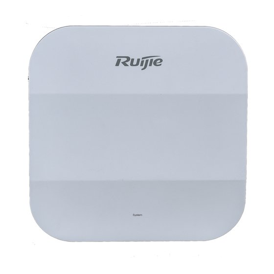
- Page 1 RG-MTFi-M520 Mobile LTE WiFi Router Installation and Basic Configuration Guide V1.0...
- Page 2 This document is provided “as is”. The contents of this document are subject to change without any notice. Please obtain the latest information through the Ruijie Networks website. Ruijie Networks endeavors to ensure content accuracy and will not shoulder any responsibility for losses and damages caused due to content omissions, inaccuracies or errors.
- Page 3 It is intended for the users who have some experience in installing and maintaining network hardware. At the same time, it is assumed that the users are already familiar with the related terms and concepts. Obtaining Technical Assistance Ruijie Networks Website: http://www.ruijienetworks.com/ Service Email: service_rj@ruijienetworks.com ...
-
Page 4: Preparation Before Installation
Single 3G/4G module, one external GPS antenna Single 3G/4G module, six external antennas Dual 3G/4G modules, three external antennas Dual 3G/4G modules, seven external antennas 1.1.2 RG-MTFi-M520 Front Panel Figure 1-1 Front Panel Rear Panel Figure 1-2 Single 3G/4G Module and One External GPS Antenna... - Page 5 Installation and Basic Configuration Guide Preparation Before Installation Figure 1-4 Dual 3G/4G Modules and Three External Antennas Figure 1-5 Dual 3G/4G Modules and Seven External Antennas Top View Figure 1-6 Top View...
- Page 6 Installation and Basic Configuration Guide Preparation Before Installation LED Indicators Color Status Description Green Solid on RG-MTFi-M520 is powered on. RG-MTFi-M520 is powered off. System Green Blinking Initialization in progress. Solid on Startup completed. WiFi1 Green 2.4 GHz WiFi is disabled.
-
Page 7: Temperature And Humidity Requirements
Please maintain a minimum clearance of 10cm at both sides and rear panel of the chassis to facilitate ventilation. To ensure the normal operation and a prolonged useful life of RG-MTFi-M520, you must maintain an appropriate temperature and humidity in the equipment room. Inappropriate temperature or humidity may damage the device. -
Page 8: Anti-Interference Requirements
Verify the installation position and the power supply way before the installation. For better maintenance experience, it is recommended that RG-MTFi-M520 should be installed on the rack above the driver seat. Then please verify the power cable, antenna specifications and installation positions. Install RG-MTFi-M520 in a position free from collisions, overheat, direct sunlight, waste, water, oil, and dust, and away from the gasbag controller, stereo equipment, ABS system, and other electrostatic-sensitive devices. - Page 9 Installation and Basic Configuration Guide Preparation Before Installation Screwdriver (Phillips screwdriver, hexagon socket-head screwdriver) Diagonal pliers Multimeter (or electrical tester pen) Headlamp (flashlight) 20-mm hole saw Nylon straps No tools are shipped with device. Users need to prepare the necessary tools and accessories.
-
Page 10: Product Installation
The power supply is properly deployed and power requirements are met. There is sufficient space for installing the device. Install RG-MTFi-M520 to a mounting bracket. The following figure shows the installation procedure. Insert the SIM card Install the anti-theft panel Install the antenna... - Page 11 Install RG-MTFi-M520 in a corresponding position according to the installation procedure above. Ensure that components are secured. Ensure that the power supply is disconnected before installing or moving RG-MTFi-M520. Make sure that RG-MTFi-M520 is installed in a proper position so that the LED indicators can be conveniently observed. Ensure that screws are fastened.
-
Page 12: Installing The Antenna
Hardware Installation and Reference Guide Product Installation For RG-MTFi-M520 with a single 3G/4G module, insert the SIM card into SIM Card-1 slot with adapter. For RG-MTFi-M520 with dual 3G/4G modules, insert the SIM cards into SIM Card-1 slot and SIM Card-2 slot with adapters. - Page 13 Check whether the antennas are properly connected. Power-off Power off RG-MTFi-M520 before maintenance to avoid damage to the SIM card, the hard disk, and the radio frequency (RF) module. After RG-MTFi-M520 is powered on, if PWR is steady on green, it indicates that RG-MTFi-M520 runs properly. If the indicator 3G/4G starts blinking, it indicates that a 3G/4G network is connected.
-
Page 14: Starting Up The Device
Hardware Installation and Reference Guide Product Installation Figure 2-7 Dual 3G/4G Modules and Three External Antennas Figure 2-8 Dual 3G/4G Modules and Seven External Antennas The LTE antennas is 9cm*5cm panel type with one side adhesive, the WiFi antennas is 5cm*5cm panel type with one side adhesive, the Bluetooth antenna is the same as WiFi antennas, the GPS antenna is 4.5cm*4cm panel type with one side adhesive. -
Page 15: Configuring The Device
You are also able to configure the ACS URL at Advanced > CWMP to make your device manageable via a cloud AC platform. The ACS URL is directed to Ruijie public cloud AC platform, MACC-BASE, which is “http://cloud.ruijienetworks.com/service/tr069servlet” by default. To manage the device in MACC-BASE, you are also required to perform actions in MACC-BASE, please refer to RG-MACC-BASE User Guide. -
Page 16: Troubleshooting
If 3G/4G indicator is off after the SIM card is inserted, check whether the 3G/4G signal is available and whether the SIM card is inserted properly. 3.1.3 WiFi Signal is Weak Check whether RG-MTFi-M520 is properly configured, and whether the indicator WiFi is on. Adjust the installed orientation of RG-MTFi-M520. ... -
Page 17: Maintenance
Pay attention to the following items during maintenance: Ensure that RG-MTFi-M520 is not wet or damaged when cleaning the vehicle. Keep RG-MTFi-M520 away from charged items, and keep RG-MTFi-M520 and the vehicle insulated. Do not replace modules or components of RG-MTFi-M520 when it is powered on.
Need help?
Do you have a question about the RG-MTFi-M520 and is the answer not in the manual?
Questions and answers