Table of Contents
Advertisement
Quick Links
Advertisement
Table of Contents

Related Manuals for Ruijie RG-RSR20-X-28 Series


Summary of Contents for Ruijie RG-RSR20-X-28 Series
- Page 1 RG-RSR20-X-28 Series Routers Hardware Installation and Reference Guide 1.0...
- Page 2 This document is provided “as is”. The contents of this document are subject to change without any notice. Please obtain the latest information through the Ruijie Networks website. Ruijie Networks endeavors to ensure content accuracy and will not shoulder any responsibility for losses and damages caused due to content omissions, inaccuracies or errors.
- Page 3 It is intended for the users who have some experience in installing and maintaining network hardware. At the same time, it is assumed that the users are already familiar with the related terms and concepts. Obtaining Technical Assistance Ruijie Networks Website: https://www.ruijienetworks.com/ Technical Support Website: https://ruijienetworks.com/support...
-
Page 5: Product Overview
1 Product Overview The RSR20-X-28 series routers are data communication products independently developed by Ruijie Networks Co. Ltd. by using advanced semiconductor technologies and communication control technologies. Ruijie series routers are developed in full compliance with international standards, therefore, it is similar to major routers in terms of use and configuration approach. - Page 6 Slot 5 RG-PA60, HSIC-2E1/CE1, HSIC-2HS, HSIC-4G-LTE Up to four HSIC modules are supported per router. Modules with OFL buttons are hot-swappable, while modules without OFL buttons are not hot-swappable. HSIC-2E1/CE1 and HSIC-2HS support hot swapping. HSIC-4G-LTE does not support hot swapping. Up to two power supply modules are supported.
-
Page 7: Product Features
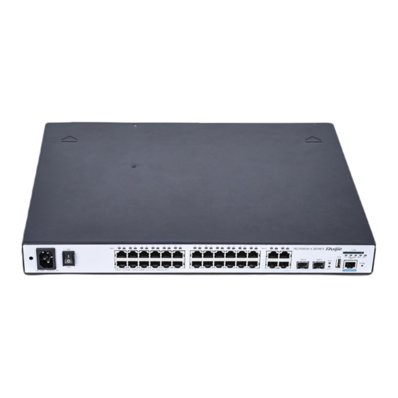
-40° C to 70° C (-40° F to 158° F) Storage Temperature Operating Humidity 5% to 95% RH (non-condensing) 5% to 95% RH (non-condensing) Storage Humidity 1.1.1 Product Features Access density and processing capability The RSR20-X-28 supports four HSIC slots, 24 GE Ethernet ports, and four GE copper ports (including two GE combo ports). - Page 8 11 12 13 14 Note: 1: Mounting hole for the power cord buckle 8: Two SFP fiber/copper combo ports 2: Power port 9: Two LEDs for SFP fiber/copper combo ports 10: USB slot 3: Power switch 11: Console/AUX combo port 4: 24 10/100/1000M Ethernet ports (GE1/0~GE1/23) 12: SD card slot...
- Page 9 Solid red The USB device is faulty. No SD card is inserted. The SD card is initialized and is not exchanging Solid green data. SD card status Blinking green The SD card is exchanging data. Solid red The SD card is faulty. The port is NOT connected.
-
Page 10: About Fixed Ports
If you cannot determine the number of the slot where the current module resides, you can run the show slots command in privileged EXE mode. The router version information includes the slot number of each module. SLOT 4 and SLOT 5 support DHSIC/power modules. 1.2 About Fixed Ports This section describes fixed ports on the RSR20-X-28 series router. - Page 11 The following table describes the basic features of the copper ports. Table 1-5 Specifications of GE ports Protocol IEEE Std 802.3-2012 Quantity Interface Type 10Base-T/100Base-TX/1000Base-T interfaces Cables 1000BASE-T interfaces: 100-ohm Category 5e UTP/STP cables, maximum cabling distance 100m 100BASE-TX interfaces: 100-ohm Category 5/5e UTP/STP cables, maximum cabling distance 100m 10BASE-T interfaces: 100-ohm Category 3/4/5/5e UTP/STP cables, maximum cabling distance 100m If the port supports Auto-MDI/MDI-X, both straight-through and crossover cables can be used.
- Page 12 Media Dependent Interface C- Media Dependent Interface D- Media Dependent Interface B- Media Dependent Interface A- Media Dependent Interface D+ Media Dependent Interface C+ Media Dependent Interface D- Media Dependent Interface C- When 1000BASE-T interfaces are in use, connect all four pairs of pins. The pin connection rule is shown in Table 1-7. Table 1-7 1000BASE-T Connection Table 1-8 100BASE-TX/10BASE-T Pin Assignments MDI Mode...
-
Page 13: Ge And Sfp Ports
Table 1-9 100BASE-TX/10BASE-T Connection 1.2.3 GE and SFP Ports Two among the four GE ports are combo ports. SFP ports support 100/1000M optical modules. Port Image and LED Indicators The following figure shows the fixed GE and SFP ports. Figure 1-5 GE and SFP Ports For descriptions of GE and SFP port Link/ACT LED indicators, see the “LED Indicators”... -
Page 14: Usb Port
Mini-GBIC-ZX50 1-port 1000BASE-ZX mini GBIC transceiver 50km Mini-GBIC-ZX80 1-port 1000BASE-ZX mini GBIC transceiver 80km Table 1-11 Available 100M SFP Module Specifications SFP Module Module Type Fiber FE-SFP-LX-MM1310 155M multi-mode FE-SFP-LX-MM1310 62.5/125um multimode optical fiber FE-SFP-LH15-SM1310 155M single-mode FE-SFP-LH15-SM1310 9/125um single-mode optical fiber The optional transmission media are as followings: Table 1-12 Optional Transmission Media and Transmission Distances Media... -
Page 15: Sd Card Slot
For descriptions of USB port indicator, see the “LED Indicators” section. Features The RSR20-X-28 series router provides one fixed USB port, through which the user can read configurations from the USB device, or save configurations to the USB device. Table 1-13 Specifications of the USB Port Index Parameters Interface Standard... -
Page 16: Func Button
5Mbps/sec max Interface Type Device SD Card Ruijie Networks SDHC card/ Kingston/ 4GB/ class_4 Hot Swapping Supported The hot swapping for the SD device must strictly follow the “Configuring Reliability” chapter in the related software configuration guide. For the avoidance of system abnormality, hot swapping is not allowed unless the command for unplugging the SD card is entered. - Page 17 Features When an SD card or a USB flash disk is inserted into the device, press the FUNC button. Then, the system searches for the installation packages and configuration files that are applicable to the current device in the root directories of the SD card and USB flash disk in sequence.
- Page 18 The module is not receiving power; the module is not properly inserted; or the module is removable. Module status LED Blinking green Initialization is in progress Initialization is complete and the module is Solid green operational. The port is not connected. The port is connected properly and is transceiving Port 0-1 status LED Link/ACT...
- Page 19 Cables The following cables can be used: V.24 DTE V.24 DCE V.35 DTE V.35 DCE V.35 DTE-V.35 DCE The figures of these cables are as below. V.24 DTE One end of this cable is the DB25 male connector, and the other end is the DB26 male connector. Figure 1-10 V.24 DTE Cable V.24 DCE One end of this cable is the DB25 female connector, and the other end is the DB26 male connector.
-
Page 20: Interface Module
Figure 1-12 V.35 DTE Cable V.35 DCE One end of this cable is the DB34 female connector, and the other end is the DB26 male connector. Figure 1-13 V.35 DCE cable V.35 DTE-V.35 DCE Both ends of this cable are DB26 male connectors. Figure 1-14 V.35 DTE-V.35 DCE Cable The cables are customer supplied. - Page 21 Figure 1-15 HSIC-2E1-CE1 Each module has an interface status indicator (Link/ACT indicator) and the module RDY indicator. And an OFL hot swapping button is provided. The following table describes LED indicators. Table 1-17 LED Indicators on the SIC-1E1-F Module Panel Identification State Meaning The module is not receiving power;...
- Page 22 Operating temperature: 0° C to 45° C (32° F to 113° F) Operating Temperature Storage temperature: -40° C to 70° C (-40° F to 158° F) Humidity Operating humidity: 5% to 95% RH EMI: GB 9254-2008 Class A EMS: GB/T 17618-1998 Cables The following cables are provided: ...
- Page 23 Figure 1-17 Balanced Cable with the RJ-45 jack Considering that you may customize cables, the following section describes connection modes and the signal. Table 1-20 Signals of the DB9 Male to RJ-45 Jack Cable DB9M RJ-45 Jack Signal RX Ring RX Tip TX Tip TX Ring...
- Page 24 Figure 1-19 HSIC-4G-LTE Module Table 1-21 LED Indicators on the HSIC-4G-LTE Module Panel Identification State Meaning The module is not receiving power. Module status LED Solid green Initialization is complete. Indicates failed dialing. Network status LED WWAN Blinking green The module is transceiving data. Solid green Indicates successful dialing.
-
Page 25: Power Supply Module
Two SMA-J connectors for antenna connection Interface Type Cables 4G antenna Mode Maximum rate for downlink Maximum rate for uplink LTE-FDD 100Mbps 50Mbps LTE-TDD 61Mbps 18Mbps UMTS HSPA+ 42Mbps 5.76Mbps Rate CDMA2000 1xEV-DO 14.7Mbps 5.4Mbps TD-SCDMA 4.2Mbps 2.2Mbps EGDE 236.8Kbps 118Kbps GPRS 85.6Kbps... - Page 26 Figure 1-20 RG-PA60 Indicator Table 1-23 LED Indicators on the RG-PA60 Module Panel Identification State Meaning The module is faulty. Module status LED Solid green The module is operational. Features Table 1-24 Specifications of the RG-PA60 Module Model RG-PA60 Rated AC Voltage Range 100VAC to 240VAC, 50-60Hz Max AC Voltage Range 90VAC to 264VAC, 50-60Hz...
-
Page 27: Supporting Multiple Protocols
5% to 95% RH (non-condensing) Storage Humidity 1.5 Features of RSR20-X-28 Series Routers For software functions, see the supporting software description. 1.5.1 Supporting Multiple Protocols Applicable to various network environments. Providing RJ-45 interfaces for twisted pairs and SFP ports, supporting Ethernet, ARP, and 802.1Q protocols. ... -
Page 28: Multiple Diagnosis And Management Tools
1.5.4 Multiple Diagnosis and Management Tools Providing complete debugging and tracing tools as well as complete DEBUG commands for easier accurate location of various network faults. Providing rich statistics and information display functions to allow the users to easily know the network performance and running status. -
Page 29: Easy Upgrade
Risk of Explosion if battery is replaced by an incorrect type. Dispose or used batteries according to the instructions. 2.2 Installation Environment Requirements Ruijie routers are intended for indoor use. For their normal operation and maximum service life, they must be installed at locations that meet the following requirements:... -
Page 30: Temperature And Humidity Requirements
Electrostatic absorption of dust occurs more easily when the relative humidity is low, which may shorten the useful life of the device and cause communication failures. The following table describes Ruijie routers' requirements for the dust content and granularity in the equipment room: Maximum diameter (μm) -
Page 31: System Grounding Requirements
0.03 0.04 0.15 0.05 0.15 0.01 2.2.3 Anti-static Requirements The router circuitry is designed with anti-static protection, but excessive static electricity may still damage router circuit boards. The static electricity of the network connected with the routers comes largely from the following sources: ... -
Page 32: Installation Tools
RSR20-X-28. 2.2.8 Anti-Lightning Requirements Ruijie series routers are provided with anti-lighting protection. However, as an electric device, it is still vulnerable to powerful lightning. Therefore, the following measures must be taken to prevent lightning: ... -
Page 33: Installing The Router
Configuration terminal that can be a terminal or a PC installed with HyperTerminal Router modules Power socket 3 Installing the Router 3.1 Installation Flowchart The following is the flowchart of installing a Ruijie series router. Follow the process to ensure a smooth installation and avoid any damage to the router. -
Page 34: Fastening The Router
Routers are usually mounted: In the cabinet On the workbench 3.2.1 Mounting on the Cabinet The Ruijie Networks RSR series router is designed with the 19-inch standard cabinet. Use the supplied fixing accessory for installation when needed. - Page 35 RSR20-X-28 can be mounted on the cabinet using the shipped sunk screw and fixing accessories. Sufficient space (1U as recommended) should be reserved above and beneath the router. The following figures show how to install an RSR20-X-28 on a rack. Figure 3-1 Brackets Mounting: Figure 3-2 Step1-Mouting the Router on a Rack...
-
Page 36: Mounting On The Workbench
No weight is placed on the top of the router. 3.3 Installing the Grounding Cable and the Power Cable Ruijie RSR20-X-28 series routers support the following AC power supply: AC: 100–240 VAC; 50 Hz to 60 Hz; Verify that the power supply meets the requirement. -
Page 37: Installing The Power Cable
grounded in the building. For common buildings, the neutral points have been buried into the ground during construction and wiring. You must verify if the power supply of the building has been properly grounded. 3.3.2 Installing the Power Cable The following table describes the procedure for installing the power cable: Verify that the router switch is off. -
Page 38: Removing The Power Cable
2) Loosen the power cord buckle, and then unplug the power cord from the power slot in the power supply module. 3.4 Connecting the Console Ruijie series routers supply an EIA/TIA-232 configuration console for local configuration. This interface enables user to complete the local configuration of the routers. - Page 39 Baud Rate Default: 9600 bps 1. Command line interface Supported Services 2. Connection to the character terminal To connect the console port of the router: Connect one end of the supplied configuration cable to the console port of the router and the other end to the DB-9 male connector used to configure the router.
-
Page 40: Installing Power Supply Modules
When you remove a service module, keep it distant from the passage in the working room to avoid any damage or accident due to bumping during removal. 3.5.3 Troubleshooting Line Modules Troubleshooting service modules as follows if the router fails to operate after you have installed a service module: ... -
Page 41: Removing Power Supply Modules
Figure 3-8 Flushing the Module and the Router Base Push the service module to the router until the interface board closely touches the backplane of the router. Tighten the fastening screws on the service module. Figure 3-9 Tightening the Fastening Screws Repeat Step 3 through Step 4 until all the service modules have been installed. -
Page 42: Starting And Configuring The Router
At Step 3, operate gently. A power supply module should be removed gently and smoothly. If you find it difficult to pull the module, do not adopt forcible measures. Instead, check if the module has been aligned with the edge of the opening on the rear panel at the base of the router. -
Page 43: Startup Process
Switch on the power supply. Switch the router to the ON position. Verification after Power-up The indicators on the front panel operate properly. Check method: For the RSR20-X-28, the SYS indicator is solid green when the router is operational after powered-on. - Page 44 Self decompressing the image succeed and will jump to 0x00010000... Ruijie General Operating System Software Release Software (tm), RGOS 10.4(3b66) Release(198287), Compiled Thu Feb 25 21:12:06 CST 2016 by ngcf67 Copyright (c) 1998-2016s by Ruijie Networks. All Rights Reserved. Neither Decompiling Nor Reverse Engineering Shall Be Allowed.
-
Page 45: Configuring The Router
4.2 Configuring the Router You need to configure a router before using it. For more information about router configuration, see the related Configuration Guide and Command Reference. 5 Troubleshooting 5.1 Power Troubleshooting For the RSR20-X-28 series, you can determine whether the power system has faults by the PWR indicator on the front panel. -
Page 46: Physical Cable Connection
Device Mode Cable 1 Peer V.35 V.35 DTE GV converter, and V.35 DTE mode cables Modem V.35 V.35 DCE Devices working in HSIC-1HS DCE mode cables V.35 DTE mode Ruijie Networks Back-to- V.35 DTE-V.35 HSIC-1HS back mode DCE cables NMX-4HSH... -
Page 47: Connecting The E1 Interface
DB9F-to- PC’s DB9M serial interface RJ45 cable interface 6.2 Ordering Information Ruijie Networks provides all previously mentioned cables, except for modem cables shown in the following table are provided by the modem manufacturer. Table: Cable ordering information Number Model Name V-03260 CAB-V.35DTE/POS26-34PM/3M... -
Page 48: Appendix A Switch Lightning Protection
V-03260 CAB-V.24DTE/POS26-DB25M/3M V.24DTE cable 030-000 V-03260 CAB-V.24DCE/POS26-DB25F/3M V.24DCE cable 031-000 V-03260 CAB-Rolled/RJ45M-RJ45M/3m Rollover cable 034-000 V-03260 RJ-45 (crystal jack)-DB9 ADAPTER/RJ45F-DB9F 060-000 female converter V-03260 RJ-45 (crystal jack)-DB25 ADAPTER/RJ45F-DB25M 061-000 male converter V-03260 RJ-45 (crystal jack)-DB25 ADAPTER/RJ45F-DB25F 062-000 female converter V-03260 CAB-E1 Non-balanced cable 035-000... - Page 49 The power arrester is not provided and the user shall purchase it to address the practical requirement. Precautions for installation: Make sure that the PE terminal of the power arrester has been well-grounded; After connecting the switch AC power plug to the socket of the power arrester (lightning protection socket), lightning protection function implements if the RUN LED is Green and the ALARM LED is OFF.
- Page 50 paste the Ethernet port arrester to the switch framework. The paste location for the Ethernet port arrester shall be as close to the grounding terminal of the switch. Based on the distance of the switch grounding terminal, cut the grounding line for the Ethernet port arrester and firmly tighten the grounding line to the grounding terminal of the switch.
-
Page 51: Appendix B Cabling Recommendations In Installation
Poor arrester grounding. The length of the grounding line should be as short as possible to ensure that it is in good contact with the switch grounding terminal. Use the multimeter to confirm the contact condition after the grounding. ... - Page 52 Route and bundle power, signal, ground cables separately. When the cables are close to each other, cross them. When power cables run parallel to signal cables, the distance between them must b All cable trays and their accessories shall be smooth and free from sharp edges. ...
- Page 53 Wrap up unnecessary or excess cables and bind them to the appropriate rack position, where device operation is not affected and no damages occur to the device and cables during debugging. Do not bind power cords to the rails for moving parts. ...
-
Page 54: Appendix C Site Selection
Bundle cables of the same type and running in the same direction into groups. Keep cables clean and straight. Cables shall be tied according to the following table. Diameter of Cable Bundle (mm) Space between Bundles (mm) 80 to 150 10 to 30 150 to 200 200 to 300... - Page 55 Pay attention to the location of the air conditioner. Keep the air conditioner from blowing wind straight toward the device or blowing water drops from the window or air vent toward the device.
Need help?
Do you have a question about the RG-RSR20-X-28 Series and is the answer not in the manual?
Questions and answers