Table of Contents
Advertisement
Advertisement
Table of Contents

Related Manuals for Ruijie RG-EG210G-E Series


Summary of Contents for Ruijie RG-EG210G-E Series
- Page 1 Ruijie RG-EG210G-E Series Routers Hardware Installation and Reference Guide...
- Page 2 This document is provided “as is”. The contents of this document are subject to change without any notice. Please obtain the latest information through the Ruijie Networks website. Ruijie Networks endeavors to ensure content accuracy and will not shoulder any responsibility for losses and damages caused due to content omissions, inaccuracies or errors.
- Page 3 It is intended for the users who have some experience in installing and maintaining network hardware. At the same time, it is assumed that the users are already familiar with the related terms and concepts. Obtaining Technical Assistance Ruijie Networks Website: https://www.ruijienetworks.com/ Technical Support Website: https://ruijienetworks.com/support...
-
Page 4: Product Overview
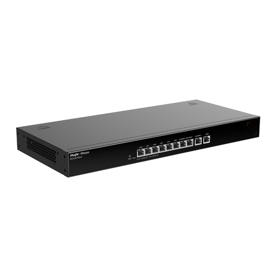
Featured with global-leading semiconductor technologies and communication control technologies, Ruijie RG-EG210G-E series router is a data communication product developed by Ruijie Networks with independent intellectual property right. The RG-EG210G-E series router is designed according to international standards, similar to the mainstream router products in the international market. - Page 5 Ruijie RG-EG210G-E Series Routers Hardware Installation and Reference Guide Product Overview ETSI EN 300 386 V2.1.1 (2016-07) Safety Standards GB4943-2011 EN 62368-1 Dimensions Width: 440mm Depth: 201.5mm (including panel) Height: 43.6mm 2.35kg Weight RG-EG210G-E is a class A product. In a domestic environment, this product may cause radio interference in which case the user may be required to take adequate measures.
- Page 6 Status Blinking green (0.5Hz): The device is not connected to Ruijie Cloud. Solid green: The device has started up, and is connected to Ruijie Cloud. Blinking green (10Hz): The device is restoring the factory settings or starting up. Solid green: The port is up.
-
Page 7: Preparation Before Installation
Ruijie RG-EG210G-E Series Routers Hardware Installation and Reference Guide Preparation before Installation 2 Preparation before Installation 2.1 Safety Suggestions To avoid personal injury and equipment damage, please carefully read the safety suggestions before you install the RG-EG210G-E series router. The following safety suggestions do not cover all possible dangers. -
Page 8: Static Discharge Damage Prevention
Ruijie RG-EG210G-E Series Routers Hardware Installation and Reference Guide Preparation before Installation supplies (that is, Action current of the leakage protector/2/Maximum leakage current of each power supply = 30/2/3.5 = 4.28). In other words, the leakage protector with 30 mA rated action current supports no more than four power supplies. -
Page 9: Temperature And Humidity
In an environment with high temperature, the equipment is subject to even greater harm, as its performance may degrade significantly and various hardware faults may occur. Table 2-1 Temperature and Humidity Requirements of the RG-EG210G-E Series Router Temperature Relative Humidity 0 º... - Page 10 2.2.5 Grounding A good grounding system is the basis for the stable and reliable operation of the RG-EG210G-E series router. It is the chief condition to prevent lightning stroke and resist interference. Please carefully check the grounding conditions on the installation site according to the grounding requirements, and perform grounding operations properly as required.
-
Page 11: Installation Tool Requirements
Ruijie RG-EG210G-E Series Routers Hardware Installation and Reference Guide Preparation before Installation The grounding device of the router must not be used as the grounding device of the electrical equipment or anti- lightning grounding device. In addition, the grounding device of the router must be deployed far away from the grounding device of the electrical equipment and anti-lightning grounding device. -
Page 12: Installing The Router
Ruijie RG-EG210G-E Series Routers Hardware Installation and Reference Guide Installing the Router 3 Installing the Router 3.1 Installation Flowchart Please take the following steps: Figure 3-1 Installation Flowchart Preparation before installation Install the device to the specified position Ground the device... -
Page 13: Mounting The Router
3.3.1 Mounting the Router to a Standard 19-inch Cabinet The RG-EG210G-E series routers follow the EIA standard dimensions and can be installed in 19-inch cabinet. Step 1: Attach the mounting brackets to the router with the supplied screws, as shown in Figure 3-1. -
Page 14: Installing Power Cables
Ruijie RG-EG210G-E Series Routers Hardware Installation and Reference Guide Installing the Router Do not use bare wire. The grounding electric resistance should be less than 1Ω. To guarantee the security of the body and the device, the router must be well-grounded. The grounding resistance for combined grounding should be less than 1Ω. - Page 15 Ruijie RG-EG210G-E Series Routers Hardware Installation and Reference Guide Installing the Router Verify that the fibers and twisted pairs match the ports. Verify that the cables have been bound properly.
-
Page 16: System Debugging
Ruijie RG-EG210G-E Series Routers Hardware Installation and Reference Guide System Debugging 4 System Debugging 4.1 Establishing the Debugging Environment Establishing the Debugging Environment Connect the PC to the LAN port of the router, and configure the PC to obtain an IP address automatically. -
Page 17: Configuring Router
Ruijie RG-EG210G-E Series Routers Hardware Installation and Reference Guide System Debugging 4.3 Configuring Router To use the router, more configuration should be made on the device. Please refer to the corresponding command reference and configuration guide. -
Page 18: Maintenance And Troubleshooting
Ruijie RG-EG210G-E Series Routers Hardware Installation and Reference Guide Maintenance and Troubleshooting 5 Maintenance and Troubleshooting 5.1 General Troubleshooting Procedure The device is not working properly after installation Check the cabinet installation Check whether the device is properly mounted on the cabinet... -
Page 19: Appendix A Connectors And Connection Media
Appendix A Connectors and Connection Media 1000BASE-T/100BASE-TX/10BASE-T Ports The 1000BASE-T/100BASE-TX/10BASE-T is a port that supports adaptation of three rates, and automatic MDI/MDIX Crossover at these three rates. The 1000BASE-T complies with IEEE 802.3ab, and uses the cable of 100-ohm Category-5 or Supper Category-5 UTP or STP, which can be up to 100 m. - Page 20 Optical Fiber Connection For the optical fiber ports, select single-mode or multiple-mode optical fibers for connection according to the fiber module connected. The connection schematic diagram is shown in Figure A-4: Figure A-4 Optical Fiber Connections...
-
Page 21: Appendix B: Cabling Recommendations In Installation
Appendix B: Cabling Recommendations in Installation When the device is installed in standard 19-inch cabinets, the cables are tied in the binding rack on the cabinet by the cabling rack, and top cabling or bottom cabling is adopted according to the actual situation in the equipment room. All cable connectors should be placed at the bottom of the cabinet in an orderly manner instead of outside the cabinet easy to touch. - Page 22 Cables of different types (such as power cords, signal cables, and grounding cables) should be separated in cabling and bundling. When they are close, crossover cabling can be adopted. In the case of parallel cabling, power cords and signal cables should maintain a space equal to or greater than 30 mm. ...
- Page 23 When cables need to bend, you should first bundle them up. However, the buckle cannot be bundled within the bend area. Otherwise, significant stress may be generated in cables, breaking cable cores. As shown in Figure D-3. Figure B-3 Bundling Up Cables (3) ...
- Page 24 The hard power cable should be fastened by the terminal connection area to prevent stress. Do not use self-tapping screws to fasten terminals. Power cables of the same type and in the same cabling direction should be bundled up into cable bunches, with cables in cable bunches clean and straight.
Need help?
Do you have a question about the RG-EG210G-E Series and is the answer not in the manual?
Questions and answers