
Subscribe to Our Youtube Channel
Related Manuals for Ruijie RG-RSR830W Series


Summary of Contents for Ruijie RG-RSR830W Series
- Page 1 Ruijie RG-RSR830W Series Router Hardware Installation and Reference Guide Document version: V1.2 Date: 2024-07-23 Copyright © 2024 Ruijie Networks...
- Page 2 All rights are reserved in this document and this statement. Any reproduction, excerption, backup, modification, transmission, translation or commercial use of this document or any portion of this document, in any form or by any means, without the prior written consent of Ruijie Networks is prohibited.
-
Page 3: Preface
Preface Intended Audience This document is intended for: Network engineers Technical support and servicing engineers Network administrators Technical Support Ruijie Networks website: https://www.ruijienetworks.com/ Technical support website: https://ruijienetworks.com/support Case portal: https://caseportal.ruijienetworks.com Community: https://community.ruijienetworks.com ... -
Page 4: Table Of Contents
Contents Preface ..............................I 1 Product Overview ..........................1 1.1 Introduction to the RG-RSR830W ..................... 1 1.2 RG-RSR830W ........................... 2 1.2.1 Product Appearance ...................... 2 1.2.2 Package Contents ......................5 1.2.3 Technical Specifications ....................6 1.2.4 LEDs and Buttons ......................10 1.3 RG-RSR830W-P ........................ - Page 5 2.1.3 Electricity ........................31 2.1.4 Storage ......................... 32 2.2 Installation Environment Requirements ................... 32 2.2.1 Load Bearing ........................ 32 2.2.2 Ventilation ........................32 2.2.3 Clearance ........................32 2.2.4 Temperature and Humidity ................... 32 2.2.5 Cleanliness ........................33 2.2.6 Anti-interference ......................33 2.2.7 Surge Protection ......................
- Page 6 3.6.2 Bundling Steps ......................40 3.7 Verifying Installation ......................... 41 3.7.1 Checking the Device ....................41 3.7.2 Checking the Cable Connection .................. 41 3.7.3 Checking Power Supply ....................41 4 Verifying the Operating Status ......................42 4.1 Setting Up the Configuration Environment ................42 4.2 Powering On the Device ......................
- Page 7 7.3 Cabling Recommendations...................... 49...
-
Page 8: Product Overview
The Wi-Fi port adopts the latest 802.11ax standard and dual-radio technology. Warning In a domestic environment, the RG-RSR830W series router may cause radio interference. The RG-RSR830W series router is not suitable for use in locations where children are likely to be present. -
Page 9: Rg-Rsr830W
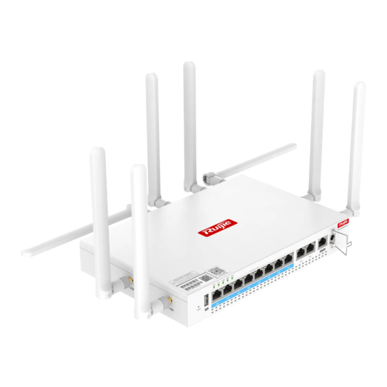
Hardware Installation and Reference Guide Product Overview Warning Replacement of a battery with an incorrect type may defeat a safeguard. Disposal of a battery into fire or a hot oven, or mechanically crushing or cutting of a battery, may result in an explosion. - Page 10 Hardware Installation and Reference Guide Product Overview 1. Front Panel Figure 1-2 Front View of the RG-RSR830W Table 1-2 Ports and Buttons on the Front Panel Port/Button Description FUNC button Multi-function button USB port USB 2.0 port, for connecting to the USB flash drive SYS LED System status LED CTL LED...
- Page 11 Hardware Installation and Reference Guide Product Overview 2. Rear Panel Figure 1-3 Rear View of the RG-RSR830W 3. Product Nameplate Figure 1-4 Nameplate of the RG-RSR830W...
-
Page 12: Package Contents
5 GHz antenna Note To obtain relevant product documentation, log in to the official website of Ruijie Networks (https://www.ruijienetworks.com). Choose Support > Download. On the displayed page, select the corresponding product category to find the product and download relevant documentation. -
Page 13: Technical Specifications
Hardware Installation and Reference Guide Product Overview 1.2.3 Technical Specifications 1. Port Specifications Table 1-4 Port Specifications Port Specifications RG-RSR830W Uplink WAN ports: 2 x 10/100/1000Base-T ports Fixed service port Downlink LAN ports: 8 x 10/100/1000Base-T portss, which can be switched to WAN ports Fixed management port 1 x RJ45 console port 1 x system status LED... - Page 14 Hardware Installation and Reference Guide Product Overview Wi-Fi Radio RG-RSR830W Radio 1: 2.4 GHz, 575 Mbps Radio 2: 5 GHz, 1.2 Gbps The following data rates (in Mbps) of 802.11 protocols are supported: 2.4 GHz 802.11b: 1, 2, 5.5, 11 ○...
- Page 15 Hardware Installation and Reference Guide Product Overview Wi-Fi Radio RG-RSR830W (54 Mbps) 802.11b/g: –91 dBm (1 Mbps), –90 dBm (5 Mbps), –87 dBm (11 Mbps) 802.11n: –85 dBm (MCS0), –67 dBm (MCS7) 11ac: VHT20: –85 dBm (MCS0), –62 dBm (MCS8) 11ac: VHT40: –82 dBm (MCS0), –57 dBm (MCS9) 11ac: VHT80: –79 dBm (MCS0), –53 dBm (MCS9) 11ax: HE80: –79 dBm (MCS0), –53 dBm (MCS9), –52 dBm (MCS11)
- Page 16 Hardware Installation and Reference Guide Product Overview Specifications RG-RSR830W Mean Time Between 100000 hours (11 year) Failure (MTBF) Caution The RG-RSR830W router adopts a fanless design. Therefore, maintain sufficient clearance around the router for air circulation. 5. Dimensions and Weight Table 1-8 Dimensions and Weight Dimensions and Weight...
-
Page 17: Leds And Buttons
Hardware Installation and Reference Guide Product Overview EN 301 489-3 EN 301 489-17 EN 300 328 Radio standard EN 301 893 EN IEC 62311 1.2.4 LEDs and Buttons Table 1-10 LEDs and Buttons LEDs Description Off: The device is not powered on. Blinking green: The motherboard is powered on, and the device is starting up. -
Page 18: Rg-Rsr830W-P
Hardware Installation and Reference Guide Product Overview With no USB flash drive inserted: DHCP deployment: Press and hold the FUNC button until SYS LED blinks green. Release the button and press it twice within 6s to import DHCP deployment configuration. Then, reset the device. - Page 19 Hardware Installation and Reference Guide Product Overview 1. Front Panel Figure 1-7 Front View of the RG-RSR830W-P Table 1-11 Ports and Buttons on the Front Panel Port/Button Description FUNC button Multi-function button USB port USB 2.0 port, for connecting to the USB flash drive SYS LED System status LED CTL LED...
- Page 20 Hardware Installation and Reference Guide Product Overview 2. Rear Panel Figure 1-8 Front View of the RG-RSR830W-P 3. Product Nameplate Figure 1-9 Nameplate of the RG-RSR830W-P...
-
Page 21: Package Contents
5 GHz antenna Note To obtain relevant product documentation, log in to the official website of Ruijie Networks (https://www.ruijienetworks.com). Choose Support > Download. On the displayed page, select the corresponding product category to find the product and download relevant documentation. -
Page 22: Technical Specifications
Hardware Installation and Reference Guide Product Overview 1.3.3 Technical Specifications 1. Port Specifications Table 1-13 Port Specifications Port Specifications RG-RSR830W-P Uplink WAN ports: 2 x 10/100/1000Base-T ports Fixed service port Downlink LAN ports: 8 x 10/100/1000Base-T ports, which can be switched to WAN ports LAN ports 2 to 9 support PoE/PoE+ Fixed management port 1 x RJ45 console port... - Page 23 Hardware Installation and Reference Guide Product Overview Wi-Fi Radio RG-RSR830W-P Peak data rate: 1.775 Gbps Data rates Radio 1: 2.4 GHz, 575 Mbps Radio 2: 5 GHz, 1.2 Gbps The following data rates (in Mbps) of 802.11 protocols are supported: 2.4 GHz 802.11b: 1, 2, 5.5, 11 ○...
- Page 24 Hardware Installation and Reference Guide Product Overview Wi-Fi Radio RG-RSR830W-P 802.11a: –89 dBm (6 Mbps), –82 dBm (24 Mbps), –78 dBm (36 Mbps), –72 dBm (54 Mbps) 802.11b/g: –91 dBm(1 Mbps), –90 dBm(5 Mbps), –87 dBm(11 Mbps) 802.11n: –85 dBm@MCS0, –67 dBm@MCS7 11ac: VHT20: –85 dBm (MCS0), –62 dBm (MCS8) Receive sensitivity 11ac: VHT40: –82 dBm (MCS0), –57 dBm (MCS9)
- Page 25 Hardware Installation and Reference Guide Product Overview Specifications RG-RSR830W-P Operating humidity: 10% RH to 90% RH (non-condensing) Humidity Storage humidity: 5% RH to 95% RH (non-condensing) Operating altitude: –500 m to +4000 m (–1640.42 ft. to +13123.36 ft.) Altitude Storage altitude: –500 m to +5000 m (–1640.42 ft. to +16404.20 ft.) Fanless design, natural heat dissipation IP rating IP30...
-
Page 26: Leds And Buttons
Hardware Installation and Reference Guide Product Overview 6. Certifications and Regulatory Compliance Table 1-18 Certifications and Regulatory Compliance of the RG-RSR830W-P Certifications and RG-RSR830W-P Regulatory Compliance Safety Regulation EN 62368-1 EN 55035 EN IEC 61000-3-2 EN 55032 EMC Regulation EN 61000-3-3 EN 301 489-1 EN 301 489-3 EN 301 489-17... -
Page 27: Eu And Uk Declaration Of Conformity
Solid yellow: indicates the PoE status. EU and UK declaration of conformity Ruijie Networks Co., Ltd. hereby declares that the device is in compliance with the essential requirements and other relevant provisions of directives 2014/53/EU, 2009/125/EC, 2011/65/EU and (EU)2015/863, and UK Radio Equipment Regulations 2017. -
Page 28: Expansion Modules
Hardware Installation and Reference Guide Product Overview Restrictions in the 5 GHz band: The 5150 to 5350 MHz frequency range is restricted to indoor use only in: AT, BE, BG, CH, CY, CZ, DE, DK, EE, EL, ES, FI, FR, HR, HU, IE, IS, IT, LI, LT, LU, LV, MT, NL, NO, PL, PT, RO, SE, SI, SK, TR, UK. Frequency Bands and Power The frequency bands and transmitting power (radiated and/or conducted) nominal limits applicable to this radio equipment are as follows:... - Page 29 Hardware Installation and Reference Guide Product Overview Table 1-20 Panel Button and LED Button and LED Description LTE antenna connector LTE antenna connector Button of the SIM card slot Button of the SIM card slot, with SIM card slots inside LTE status LED LTE status LED Note...
- Page 30 Hardware Installation and Reference Guide Product Overview Communication Standard 3GPP E-UTRA Release 12 Safety Regulation EN 62368-1 EMC Regulation EN 301 489-1 EN 301 489-52 Radio Standard EN301 908-1 EN301 908-2 EN301 908-13 EN IEC 62311 3. Product Nameplate Figure 1-12 Nameplate of the SIC-LTE-GD Figure 1-13 Nameplate Style...
-
Page 31: Sic-Lte-Gs
Hardware Installation and Reference Guide Product Overview 1.5.2 SIC-LTE-GS 1. Product Appearance The SIC-LTE-GS is a 4G Dual SIM Single Standby module that supports the WCDMA, TD-LTE, LTE FDD standards. It can be inserted into an RG-RSR830 series router with SIC slots to enable wired routing and wireless data transmission on 3G/4G public network. - Page 32 Hardware Installation and Reference Guide Product Overview LTE-FDD: Class 3 (23 dBm± 2 dB) Transmit power LTE-TDD: Class 3 (23 dBm± 2 dB) WCDMA: Class 3 (23 dBm± 2 dB) Excluding antennas: 155 mm x 93 mm x 21 mm (6.10 in. x 3.66 in. x 0.83 in.) Unit dimensions (W x D x H) Including external antennas: 155 mm x 138.3 mm x 176.5 mm (6.10 in.
-
Page 33: Sic-5G-G
Hardware Installation and Reference Guide Product Overview Figure 1-16 Nameplate Style 1.5.3 SIC-5G-G 1. Product Appearance The SIC-5G-G is a Dual SIM Single Standby 5G data module that supports the WCDMA, TD-LTE, LTE FDD, and 5G standards. It can be inserted into the RG-RSR830 series device with SIC slots to enable wired routing and wireless data transmission on 3G/4G/5G public network. - Page 34 Hardware Installation and Reference Guide Product Overview Table 1-27 Panel LED Name Description LED Status Off: System services are not available. Solid green: 5G services are available, with strong signal strength. SIM card status Blinking green: 5G services are available, with weak signal strength. Solid orange: 4G services are available, with strong signal strength.
-
Page 35: Sic-2Sfp
Hardware Installation and Reference Guide Product Overview 3. Product Nameplate Figure 1-18 Nameplate of the SIC-5G-G Figure 1-19 Nameplate Style 1.5.4 SIC-2SFP 1. Product Appearance The SIC-2SFP is a 1000M expansion module for optical transceiver expansion. It can be inserted into the RG- RSR830 series device with SIC slots and provides two 1000M SFP ports, as shown in Figure 1-20. - Page 36 Hardware Installation and Reference Guide Product Overview Table 1-29 Panel Button and LED Button and LED Description SFP port SFP port Port status LED SFP port status LED Table 1-30 Panel LED Name Description LED Status Off: The port is Down. Solid green: The optical port is Up at the rate of 1G.
- Page 37 Hardware Installation and Reference Guide Product Overview 3. Product Nameplate Figure 1-21 Nameplate of the SIC-2SFP Figure 1-22 Nameplate Style...
-
Page 38: Preparing For Installation
Hardware Installation and Reference Guide Preparing for Installation Preparing for Installation Safety Precautions Note To avoid personal injury and device damage, carefully read the safety precautions before you install the device. The following safety precautions do not cover all possible dangers. 2.1.1 General Safety Precautions ... -
Page 39: Storage
Hardware Installation and Reference Guide Preparing for Installation Check whether there are potential risks in the working area. For example, check whether the ground is wet. Find out the position of the indoor emergency power switch before installation. Cut off the power switch in the case of accidents. -
Page 40: Cleanliness
Hardware Installation and Reference Guide Preparing for Installation A high temperature can accelerate the aging process of insulation materials, greatly reducing the reliability of the device and severely affecting its service life. Note The ambient temperature and humidity are measured at the point that is 1.5 m (59.06 in.) above the floor and 0.4 m (15.75 in.) before the device rack when there is no protective plate in front or at the back of the rack. -
Page 41: Surge Protection
Anti-ESD glove, wire stripper, common crimping plier, RJ45 crimping plier, and wire cutter Meter Multimeter and bit error rate tester (BERT) Relevant PC, display, and keyboard Device Note The RG-RSR830W series router is not shipped with a tool kit. You need to prepare a tool kit by yourself. -
Page 42: Installation
Hardware Installation and Reference Guide Installation Installation Secure the RG-RSR830W series router indoors. Caution Before installing the device, make sure that you have carefully read the requirements described in Chapter 2 . -
Page 43: Installation Procedure
Hardware Installation and Reference Guide Installation Installation Procedure Figure 3-1 Installation Procedure Checking Before Installation Carefully plan and arrange the installation location, networking, power supply, and cabling before installing the device. -
Page 44: Precautions
3.4.2 Installing the Device Against a Wall The RG-RSR830W series router can be wall mounted against a wall: (1) Drill two holes in parallel on the wall, with a spacing of 200 mm (7.87 in.). (2) Tap the wall anchors into the holes and drive the screws into the wall anchors. -
Page 45: Installing A Sim Card On A Lte Expansion Module
Hardware Installation and Reference Guide Installation Do not place the router in a place where it will be exposed to moisture or excessive heat. Keep the router away from devices with strong electromagnetic interference, such as Bluetooth devices, microwave ovens, or cordless phones. - Page 46 Hardware Installation and Reference Guide Installation Figure 3-4 Removing the Rear Faceplate of the Device (2) Align the expansion module with the opening edge of the expansion module slot in the rear panel of the router, and push the expansion module into the router until the expansion module is flush with the rear panel of the router.
-
Page 47: Connecting Cables
Hardware Installation and Reference Guide Installation (4) Install the antenna clockwise on the expansion module. Figure 3-6 Installing the Antenna Connecting Cables Connect a twisted pair cable to the LAN port of the device. For details about the twisted-pair cable connection sequence supported by the device, see Connectors and Media. -
Page 48: Verifying Installation
Hardware Installation and Reference Guide Installation Verifying Installation 3.7.1 Checking the Device Verify that the external power supply matches the device. Verify that the device is securely fastened. 3.7.2 Checking the Cable Connection Make sure that the twisted pair cable matches the port. ... -
Page 49: Verifying The Operating Status
Hardware Installation and Reference Guide Verifying the Operating Status Verifying the Operating Status Setting Up the Configuration Environment Power on the router using a power adapter. When setting up the environment, pay attention to the following points: When the device is powered through a power adapter, ensure that the power cord is properly connected and meets safety requirements. -
Page 50: Monitoring And Maintenance
You can run related commands on the CLI of the device to remotely monitor the device status, including: Port configuration and status System logs Note For details about the commands, see the configuration guide. The device supports remote maintenance. Hardware Maintenance If the hardware is faulty, contact Ruijie technical support. -
Page 51: Faqs
Check whether the power er supply is properly connected Check whether LEDs are normal Check whether cables are properly connected to ports Contact Ruijie technical support to check k whether hardware faults exist Common Faults 6.2.1 Ethernet Port Is Not Working After the Ethernet Cable Is Installed Check whether the device at the other end of the Ethernet cable is working properly. - Page 52 Hardware Installation and Reference Guide FAQs (4) Move the Wi-Fi client closer to the device.
-
Page 53: Appendix
Appendix Mini-GBIC (SFP) Modules Ruijie provide supporting SFP modules (mini-GBIC modules) based on the port types of switch modules. You can select a module to suit your specific needs. This document provides models and technical specifications of some 1000M SFP modules for reference. For details about the technical specifications, see the Ruijie Transceiver Installation and Reference Guide. - Page 54 Hardware Installation and Reference Guide Appendix GE-SFP-LX20-SM1550- 1550TX/131 Single- BIDI mode Table 7-2 Cabling Specifications of SFP Modules Optical Fiber Max Cabling SFP Model Port Type Core Size (um) Type Distance 62.5/125 275m MINI-GBIC-SX-MM850 Multi-mode 50/125 550m MINI-GBIC-LX-SM1310 Single-mode 9/125 10 km 62.5/125 275 m...
-
Page 55: Connectors And Media
Hardware Installation and Reference Guide Appendix GE-SFP-LX Single-mode 9/125 10 km Cat 5 unshielded or shielded twisted Mini-GBIC-GT RJ45 cable 100 m pair cables or higher Cuation An optical module is a laser transmitter. Do not stare at any light source to prevent it from burning your eyes. - Page 56 Hardware Installation and Reference Guide Appendix 100BASE-TX/10BASE-T uses CAT 3, CAT 4, and CAT 5 100-ohm UTP/STP, and 1000BASE-T uses CAT 5 100- ohm UTP/STP for connections with a maximum distance of 100 meters (328 ft.). Table 7-3 shows 100BASE- TX/10BASE-T pin assignments.
- Page 57 Hardware Installation and Reference Guide Appendix ○ The minimum bend radius of a high-speed cable such as an SFP+ cable should be over five times its diameter. If the cable is constantly bent, plugged, or unplugged, the bend radius should be over 10 times greater than its diameter.
- Page 58 Hardware Installation and Reference Guide Appendix Figure 7-4 Bundling Up Cables (2) ○ When cables need to be bent, bundle them up but do not tie cable them where the cables will be bent, as shown in Figure 7-5. Figure 7-5 Bundling Up Cables (3) ○...
- Page 59 Hardware Installation and Reference Guide Appendix Figure 7-6 Cable Fastening ① Flat washer ③ Spring washer Notes: ② Nut ④ Flat washer ○ When using a stiff cable, fix it near the cable lug to avoid stress on the lug and cable. ○...
Need help?
Do you have a question about the RG-RSR830W Series and is the answer not in the manual?
Questions and answers