
Subscribe to Our Youtube Channel
Related Manuals for Ruijie RG-RSR30-XA Series


Summary of Contents for Ruijie RG-RSR30-XA Series
- Page 1 RG-RSR30-XA Series Router Hardware Installation and Reference Guide Document Version: V1.3 Date: 2022-10-31 Copyright © 2023 Ruijie Networks...
- Page 2 All rights are reserved in this document and this statement. Any reproduction, excerption, backup, modification, transmission, translation or commercial use of this document or any portion of this document, in any form or by any means, without the prior written consent of Ruijie Networks is prohibited.
-
Page 3: Preface
Preface Intended Audience This document is intended for: Network engineers Technical support and service engineers Network administrators Technical Support Ruijie Networks website: https://www.ruijienetworks.com/ Technical support website: https://ruijienetworks.com/support Case portal: https://caseportal.ruijienetworks.com Community: https://community.ruijienetworks.com ... - Page 4 Warning An alert that calls attention to important rules and information that if not understood or followed can result in data loss or equipment damage. Caution An alert that calls attention to essential information that if not understood or followed can result in function failure or performance degradation.
-
Page 5: Table Of Contents
Contents Preface ..............................i 1 Product Overview ..........................7 1.1 Introduction to RG-RSR30-XA Series ..................7 1.2 RG-RSR30-XA-24........................7 1.2.1 Package Contents ......................7 1.2.2 Product Appearance ...................... 8 1.2.3 Technical Specifications ....................12 1.3 RG-PA150IB-F Power Module ....................13 1.3.1 Module Appearance ..................... - Page 6 2.1 Safety Precautions ........................24 2.1.1 General Safety Precautions ..................24 2.1.2 Movement ........................24 2.1.3 Electricity ........................24 2.1.4 ESD ..........................25 2.1.5 Laser ..........................25 2.1.6 Storage ......................... 26 2.2 Installation Site Requirements ....................26 2.2.1 Bearing ......................... 26 2.2.2 Ventilation ........................
- Page 7 3.3.2 Installing the Device on a Workbench ................. 32 3.4 Installing a Power Module ......................33 3.4.1 Installing a Power Module .................... 33 3.4.2 Removing a Power Module ..................34 3.4.3 Installing Power Cords and Grounding Cables ............34 3.4.4 Removing Power Cords and Grounding Cables ............35 3.5 Installing Service Modules .......................
- Page 8 6 Troubleshooting ..........................40 6.1 Configuration System Troubleshooting ................... 40 7 Appendix ............................41 7.1 Self-made Cable Connection Modes ..................41 7.2 Labeling Process ........................43 7.2.1 Manual Writing of Labels ..................... 43 7.2.2 Pasting Labels ......................43 7.2.3 Label Contents ......................44 7.3 Cabling .............................
-
Page 9: Product Overview
Product Overview Introduction to RG-RSR30-XA Series RG-RSR30-XA series multi-service routers are centralized devices with high-performance processing and high- density access capabilities. It supports the Border Gateway Protocol (BGP), IP multicast protocols, and rich QoS features, provides power modules in redundancy mode, and allows users to configure optional modules. They can function as core routers on small- and medium-sized enterprise networks, or aggregation routers on large- scale industry networks. -
Page 10: Product Appearance
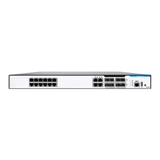
Hardware Installation and Reference Guide Product Overview Product Appearance 1. Front Panel Figure 1-1 Front Panel Ports, LEDs, and Buttons on the Front Panel Item Description Solid yellow: A link is set up on the port at a rate of 10/100 Mbps. LED of the Blinking yellow: A link is set up on the port at a rate of 10/100 Mbps and data is transmitted on the link. - Page 11 Hardware Installation and Reference Guide Product Overview Item Description Solid green: The USB flash drive works properly. USB port LED Solid red: The USB flash drive encounters an exception. Off: The USB flash drive is not installed. Console port It is connected to the console for onsite configuration. Fan module status: Green: The fan module works properly.
- Page 12 Hardware Installation and Reference Guide Product Overview Figure 1-2 Location of the Nameplate 2. Rear Panel Figure 1-3 Rear Panel...
- Page 13 Hardware Installation and Reference Guide Product Overview Description of the Rear Panel Module Slot and Description Grounding Stud Slot 1 HSIC-E and HSIC service module slot 1 Slot 3 HSIC-E and HSIC service module slot 3 Slot 4 HSIC-E and HSIC service module slot 4 Grounding stud Protection against lightning strikes and interference Power module slot 0: Install the power module first and then connect the AC...
-
Page 14: Technical Specifications
Hardware Installation and Reference Guide Product Overview Technical Specifications Technical Specifications of the RG-RSR30-XA-24 Model RG-RSR30-XA-24 Service Module Slots Four slots, and HSIC and HSIC-E service modules supported Number of Power Slots Supported (the power module and HSIC-2E1/CE1 service module support hot Hot Swapping swapping) Power Redundancy... -
Page 15: Rg-Pa150Ib-F Power Module
Hardware Installation and Reference Guide Product Overview RG-PA150IB-F Power Module Module Appearance Figure 1-4 Appearance of the RG-PA150IB-F Power Module RG-PA150IB-F LED Description Green: The power output is normal. Power module status Red: The power output is abnormal. Off: The power cord is not inserted, the power module is not installed properly, or the power module has no output. -
Page 16: Technical Specifications
Hardware Installation and Reference Guide Product Overview Technical Specifications Technical Specifications of the RG-PA150IB-F Power Module Model RG-PA150IB-F Rated AC Input Voltage 100 V AC to 240 V AC, 50 Hz to 60 Hz Range Maximum AC Input Voltage 90 V AC to 264 V AC, 50 Hz to 60 Hz Range Maximum Output Power 150 W... -
Page 17: Service Modules
Hardware Installation and Reference Guide Product Overview Service Modules HSIC-2E1/CE1 Service Module 1. Module Appearance Figure 1-5 Appearance of the HSIC-2E1/CE1 Service Module Description of LEDs and Button of the HSIC-2E1/CE1 Service Module Description Function module status LED: Blinking green: The module is being initialized. Solid green: Initialization is complete, and the module works properly. -
Page 18: Hsic-4G-Lte Service Module
Hardware Installation and Reference Guide Product Overview 2. Technical Specifications Technical Specifications of the HSIC-2E1/CE1 Service Module Number of Ports Connector Type DB9 female connector Cable Balanced or unbalanced cable Standards ITU-T G.703 Compliance Operating temperature: 0º C to 50º C (32º F to 122º F) Temperature Storage temperature: –40º... - Page 19 Hardware Installation and Reference Guide Product Overview Description Network status LED: Solid green: The dial-up is successful. WWAN Blinking green: The port is receiving or sending data. Off: The dial-up fails. 4G service LED: Solid green: 4G services are available. Off: 4G services are unavailable.
-
Page 20: Pluggable Modules
Hardware Installation and Reference Guide Product Overview 3. Cables One HSIC-4G-LTE service module needs to be used with two antennas. You only need to connect the external antenna to the external antenna interface ANT 0 or ANT 1 correctly, and rotate and fasten them. -
Page 21: 10Ge Optical Modules
An optical module is a laser transmitter. Do not look directly into the optical module to prevent it from burning your eyes. Note SFP+ module types are subject to change without prior notice. For more accurate information about the optical modules, contact Ruijie marketing or technical support personnel. -
Page 22: Cables
Hardware Installation and Reference Guide Product Overview For XG-SFP-ER-SM1550 and XG-SFP-ZR-SM1550 modules, do not use short-distance optical cables for interconnection to avoid overload on the optical receiver of the module. If the optical power at the receiving end of the module is greater than or equal to –1 dBm, you need to add an appropriate attenuator at the receiving end of the module to make the optical power at the receiving end less than –1 dBm. - Page 23 Hardware Installation and Reference Guide Product Overview Max. Connector Core Size (μm) SFP Type Fiber Type Cabling Type Distance GE-eSFP-LX-SM1310 Single-mode 9/125 10 km Mini-GBIC-LH40 Single-mode 9/125 40 km GE-SFP-LX20-SM1310-BIDI Single-mode 9/125 20 km GE-SFP-LX20-SM1550-BIDI Single-mode 9/125 20 km GE-SFP-LH40-SM1310-BIDI Single-mode 9/125 40 km...
-
Page 24: E1 Cables
Hardware Installation and Reference Guide Product Overview E1 Cables 1. Balanced Cable (Standard RJ45 Connector) The cable has a DB9 male connector on one end and a standard RJ45 connector on the other end. The characteristic impedance of the cable is 120 ohm. Figure 1-7 Balanced Cable (Standard RJ45 Connector) Description of Signal Connections of the Balanced Cable (Standard RJ45 Connector) - Page 25 Hardware Installation and Reference Guide Product Overview DB9M RJ45 Signal RX Tip TX Tip TX Ring 3. Unbalanced Cable The cable has a DB9 male connector on one end and two BNC male connectors on the other end. The characteristic impedance of the cable is 75 ohm. Figure 1-9 Unbalanced Cable Cables are not delivered and need to be purchased separately or supplied.
-
Page 26: Preparing For Installation
Hardware Installation and Reference Guide Preparing for Installation Preparing for Installation Safety Precautions Note To avoid personal injury and device damage, carefully read the safety precautions before you install the device. The following safety precautions may not cover all possible dangers. General Safety Precautions Danger ●... -
Page 27: Esd
Hardware Installation and Reference Guide Preparing for Installation ● Direct or indirect contact with high voltage or mains power supply through wet objects may cause fatal dangers. ● Replacement of a battery with an incorrect type that can defeat a safeguard (for example,in the case of some lithium battery types). -
Page 28: Storage
Hardware Installation and Reference Guide Preparing for Installation When an optical transceiver is working, ensure that the port has been connected to a fiber cable or covered with a dust cap, to keep out dust and prevent it from burning your eyes. ... -
Page 29: Cleanliness
Hardware Installation and Reference Guide Preparing for Installation A high temperature can accelerate the aging of insulation materials, greatly reducing the reliability of the device and severely affecting its service life. For details about the operating temperature and operating humidity, see Technical Specifications. Note The ambient temperature and humidity of the device are measured at the point that is 1.5 m (59.06 in.) above the floor and 400 mm (15.75 in.) before the device when there is no protective plate in front or at the rear of the... -
Page 30: Grounding
Hardware Installation and Reference Guide Preparing for Installation Grounding A good grounding system is the basis for stable and reliable operation of the device, preventing lightning strokes and resisting interference. Carefully check the grounding conditions at the installation site according to the grounding requirements, and perform grounding operations properly as required. -
Page 31: Cabinet Installation Requirements
Hardware Installation and Reference Guide Preparing for Installation Maintain a proper clearance around air intakes and outlets for heat dissipation. Maintain a minimum clearance of 150 mm (5.91 in.) around the ventilation openings for heat dissipation. You are advised to install the device in a standard 19-inch rack. Or, place the device on a clean workbench. In hot areas, air-conditioning is recommended. -
Page 32: Tools
Hardware Installation and Reference Guide Preparing for Installation Tools Tools Category Description Common tools Phillips screwdriver, power cords, Ethernet cables, cage nuts, diagonal plier, and cable ties Special tools ESD gloves, wire stripper, common crimping plier, RJ45 crimping plier, and wire cutter Meters Multimeter Relevant... -
Page 33: Installing The Device
Hardware Installation and Reference Guide Installing the Device Installing the Device Verify that requirements described in chapter 2 have been me Installation Procedure Figure 3-1 Installation Procedure (1) Installation Preparation (2) Fixing the Device Location (3) Installing a Power Module (4) Installing Service Modules... -
Page 34: Installation Preparation
Hardware Installation and Reference Guide Installing the Device Installation Preparation The installation site provides sufficient space for heat dissipation. The installation site meets the temperature and humidity requirements of the device. The power supply is available in the installation site and meets current requirements. ... -
Page 35: Installing A Power Module
Hardware Installation and Reference Guide Installing the Device Installing a Power Module Figure 3-2 Installing the Power Module Figure 3-3 Removing the Power Module Installing a Power Module (1) Remove the filler panel in the slot where the power module needs to be installed. (2) Align the device power module with the opening edge of the power module slot on the rear panel of the device. -
Page 36: Removing A Power Module
Hardware Installation and Reference Guide Installing the Device (3) Push the power module into the slot until the power module is in close contact with the rear panel of the device, and snap metal latch on the power module to the right. Danger Before installing the power module, ensure that the power control switch of the power module is off and that the power cord is not connected to the power module and the power outlet. -
Page 37: Removing Power Cords And Grounding Cables
Hardware Installation and Reference Guide Installing the Device (3) Check whether the power LED on the front panel of the device is on. If the LED is on, the power supply is connected correctly. Danger Use the delivered power cords. Otherwise, security accidents may occur. Removing Power Cords and Grounding Cables The procedure for removing power cords is as follows: (1) Verify that the circuit breaker switch on the power supply side is off. -
Page 38: Removing A Service Module
Hardware Installation and Reference Guide Installing the Device Removing a Service Module (1) Unplug the Ethernet cable from the service module to be removed. (2) Use a Phillips screwdriver to remove fastening screws on both sides of the service module counterclockwise. (3) Grasp screws at both ends of the service module with both hands, and drag the service module out of the slot. -
Page 39: Verifying The Operating Status
Hardware Installation and Reference Guide Verifying the Operating Status Verifying the Operating Status Setting Up the Configuration Environment Connect a PC to the console port of the device by using an Ethernet cable. Figure 4-1 Setting Up the Configuration Environment When the device is used for the first time, the device must be configured through the console port: (1) Connect the terminal's serial port to the device's console port (configuration port) through a standard RS232 cable. -
Page 40: Powering On The Device
Hardware Installation and Reference Guide Verifying the Operating Status Powering On the Device Checklist Before Power-on Verify that the device is fully grounded. Verify that fan modules and power modules are securely seated. Verify that power cords are properly connected. ... -
Page 41: Monitoring And Maintenance
Hardware Installation and Reference Guide Monitoring and Maintenance Monitoring and Maintenance Monitoring Devices Through CLI Commands You can run related commands on the CLI of the device to remotely monitor the device status, including: Module or card installation status ... -
Page 42: Troubleshooting
Hardware Installation and Reference Guide Troubleshooting Troubleshooting Configuration System Troubleshooting After the device is powered on, if the configuration system fails, no information is display or garbled characters are displayed on the terminal. If the terminal does not display any information, perform the following check: ... -
Page 43: Appendix
Hardware Installation and Reference Guide Appendix Appendix Self-made Cable Connection Modes The connection method and signal description are provided considering self-made cables. Keep the back of the RJ45 locking clip facing yourself. The signal lines are numbered 1 to 8 from left to right. Figure 7-1 Cable Connection Modes and Signals 1000BASE-T Pin Assignments... - Page 44 Hardware Installation and Reference Guide Appendix Figure 7-2 1000BASE-T Twisted Pair Connections 100BASE-TX/10BASE-T Pin Assignments MDI Mode MDI-X Mode Output Transmit Data+ Input Receive Data+ Output Transmit Data- Input Receive Data- Input Receive Data+ Output Transmit Data+ Input Receive Data- Output Transmit Data- 4, 5, 7, 8 Not used...
-
Page 45: Labeling Process
Hardware Installation and Reference Guide Appendix Labeling Process Manual Writing of Labels Writing tool: black gel pen Pasting Labels Fill in the label content on the full-page label paper before attaching the label, and then uncover and paste it on the power cord or signboard wire buckle. -
Page 46: Label Contents
Hardware Installation and Reference Guide Appendix Figure 7-5 Steps and Methods for Attaching Signal Line Labels Label Contents The contents of the two sides of the label identify the location of the ports connected to the two ends of the power cord. -
Page 47: Cabling
Hardware Installation and Reference Guide Appendix Cabling When the device is installed in a standard 19-inch cabinet, secure the cables around the cable management brackets. Top or bottom cabling is adopted according to the actual situation in the equipment room. All cable connectors should be placed at the bottom of the cabinet, and cannot be exposed outside the cabinet. - Page 48 Hardware Installation and Reference Guide Appendix Route and bundle power, signal, ground cables separately. When the cables are close to each other, cross them. Mixed bundling is not allowed. When they are close to each other, crossover cabling is recommended. In the case of parallel cabling, maintain a minimum distance of 30 mm (1.18 in.) between power cords and signal cables.
- Page 49 Hardware Installation and Reference Guide Appendix The power cords connecting moving parts such as grounding cables should be reserved with some access after being assembled to avoid suffering tension or stress. After the moving part is installed, the remaining cable part should not touch heat sources, sharp corners, or sharp edges.
-
Page 50: Equipment Room Selection
Hardware Installation and Reference Guide Appendix Equipment Room Selection The equipment room should be at least 5 km away from heavy pollution sources, such as the smelter works, coal mine, and thermal power plant. The equipment room should be at least 3.7 km away from medium pollution sources, such as the chemical factory, rubber factory, and electroplating factory.
Need help?
Do you have a question about the RG-RSR30-XA Series and is the answer not in the manual?
Questions and answers