Table of Contents

Related Manuals for Cabletron Systems SmartSTACK ETHERNET ELS10-27


Summary of Contents for Cabletron Systems SmartSTACK ETHERNET ELS10-27
- Page 1 SmartSTACK ETHERNET ELS10-27 USER GUIDE ETHERNET SWITCH PORT STATUS MODE STATUS ELS10-27TX TX ACT FDX MON RESET RX COL 100 USR 9032800-01 EPIM100 10BASE-T/100BASE-TX...
- Page 3 NOTICE Cabletron Systems reserves the right to make changes in specifications and other information contained in this document without prior notice. The reader should in all cases consult Cabletron Systems to determine whether any such changes have been made. The hardware, firmware, or software described in this manual is subject to change without notice. IN NO EVENT SHALL CABLETRON SYSTEMS BE LIABLE FOR ANY INCIDENTAL, INDIRECT, SPECIAL, OR CONSEQUENTIAL DAMAGES WHATSOEVER (INCLUDING BUT NOT LIMITED TO LOST PROFITS) ARISING OUT OF OR RELATED TO THIS MANUAL OR...
-
Page 4: Fcc Notice
Notice FCC NOTICE This device complies with Part 15 of the FCC rules. Operation is subject to the following two conditions: (1) this device may not cause harmful interference, and (2) this device must accept any interference received, including interference that may cause undesired operation. NOTE: This equipment has been tested and found to comply with the limits for a Class A digital device, pursuant to Part 15 of the FCC rules. -
Page 5: Program License Agreement
CABLETRON SYSTEMS, INC. PROGRAM LICENSE AGREEMENT IMPORTANT: THIS LICENSE APPLIES FOR USE OF PRODUCT IN THE FOLLOWING GEOGRAPHICAL REGIONS: CANADA MEXICO CENTRAL AMERICA SOUTH AMERICA BEFORE OPENING OR UTILIZING THE ENCLOSED PRODUCT, CAREFULLY READ THIS LICENSE AGREEMENT. This document is an agreement (“Agreement”) between You, the end user, and Cabletron Systems, Inc. - Page 6 Notice If the Program is exported from the United States pursuant to the License Exception TSR under the U.S. Export Administration Regulations, in addition to the restriction on transfer set forth in Sections 1 or 2 of this Agreement, You agree not to (i) reexport or release the Program, the source code for the Program or technology to a national of a country in Country Groups D:1 or E:2 (Albania, Armenia, Azerbaijan, Belarus, Bulgaria, Cambodia, Cuba, Estonia, Georgia, Iraq, Kazakhstan, Kyrgyzstan, Laos, Latvia, Libya, Lithuania, Moldova, North Korea, the People’s Republic of China,...
- Page 7 CABLETRON SYSTEMS SALES AND SERVICE, INC. PROGRAM LICENSE AGREEMENT IMPORTANT: THIS LICENSE APPLIES FOR USE OF PRODUCT IN THE UNITED STATES OF AMERICA AND BY UNITED STATES OF AMERICA GOVERNMENT END USERS. BEFORE OPENING OR UTILIZING THE ENCLOSED PRODUCT, CAREFULLY READ THIS LICENSE AGREEMENT. This document is an agreement (“Agreement”) between You, the end user, and Cabletron Systems Sales and Service, Inc.
- Page 8 Notice If the Program is exported from the United States pursuant to the License Exception TSR under the U.S. Export Administration Regulations, in addition to the restriction on transfer set forth in Sections 1 or 2 of this Agreement, You agree not to (i) reexport or release the Program, the source code for the Program or technology to a national of a country in Country Groups D:1 or E:2 (Albania, Armenia, Azerbaijan, Belarus, Bulgaria, Cambodia, Cuba, Estonia, Georgia, Iraq, Kazakhstan, Kyrgyzstan, Laos, Latvia, Libya, Lithuania, Moldova, North Korea, the People’s Republic of China,...
- Page 9 CABLETRON SYSTEMS LIMITED PROGRAM LICENSE AGREEMENT IMPORTANT: THIS LICENSE APPLIES FOR THE USE OF THE PRODUCT IN THE FOLLOWING GEOGRAPHICAL REGIONS: EUROPE MIDDLE EAST AFRICA ASIA AUSTRALIA PACIFIC RIM BEFORE OPENING OR UTILIZING THE ENCLOSED PRODUCT, CAREFULLY READ THIS LICENSE AGREEMENT. This document is an agreement (“Agreement”) between You, the end user, and Cabletron Systems Limited (“Cabletron”) that sets forth your rights and obligations with respect to the Cabletron software program (“Program”) in the package.
- Page 10 Notice If the Program is exported from the United States pursuant to the License Exception TSR under the U.S. Export Administration Regulations, in addition to the restriction on transfer set forth in Sections 1 or 2 of this Agreement, You agree not to (i) reexport or release the Program, the source code for the Program or technology to a national of a country in Country Groups D:1 or E:2 (Albania, Armenia, Azerbaijan, Belarus, Bulgaria, Cambodia, Cuba, Estonia, Georgia, Iraq, Kazakhstan, Kyrgyzstan, Laos, Latvia, Libya, Lithuania, Moldova, North Korea, the People’s Republic of China,...
-
Page 11: Declaration Of Conformity
DECLARATION OF CONFORMITY Application of Council Directive(s): Manufacturer’s Name: Manufacturer’s Address: European Representative Name: European Representative Address: Conformance to Directive(s)/Product Standards: Equipment Type/Environment: We the undersigned, hereby declare, under our sole responsibility, that the equipment packaged with this notice conforms to the above directives. Manufacturer Mr. - Page 12 Notice...
-
Page 13: Table Of Contents
CHAPTER 1 INTRODUCTION 1.1 About This Manual ...1-1 1.2 Getting Help ...1-2 1.3 Document Conventions ...1-3 1.4 Related Documentation...1-4 1.5 Overview ...1-4 1.5.1 SmartSTACK Ethernet ELS10-27 Architecture...1-5 1.5.2 SmartSTACK Ethernet ELS10-27 Functionality ...1-5 1.5.3 SmartSTACK Ethernet ELS10-27 Bridge Address Table...1-10 1.5.4 SmartSTACK Ethernet ELS10-27 Port Mirroring...1-11 1.5.5 SmartSTACK Ethernet ELS10-27 Sample Applications ...1-12 1.5.6 VLANs...1-13... - Page 14 Contents 3.6 Displaying Bridging Functions ...3-10 3.7 Enabling Trunking ...3-10 3.8 Disabling Trunking ...3-12 3.9 Displaying Trunking Status...3-12 3.10 Port Mirroring...3-14 3.11 Defining and Deleting Workgroups...3-14 3.12 Assigning a ComMunity Name ...3-16 3.13 Configuring Broadcast/Multicast Storm Protection...3-17 3.14 Modifying MIB Variables...3-17 3.15 System Contact ...3-18 3.16 System Name ...3-18 3.16.1 System Location ...3-18...
- Page 15 CHAPTER 5 SMARTSTACK ETHERNET ELS10-27 DIAGNOSTICS AND TROUBLESHOOTING 5.1 Power-up Diagnostics ...5-1 5.1.1 Power-up LED Sequence ...5-1 5.1.2 Specific Power-up Tests ...5-2 5.1.3 Power-up Diagnostics Results ...5-2 5.2 Responses to Failures at Power-up ...5-2 5.3 Status and Activity Indicators...5-3 5.4 Troubleshooting ...5-5 5.5 SmartSTACK Ethernet ELS10-27 Does Not Power Up...5-5 5.5.1 Connectivity Problems...5-5 5.5.2 SmartSTACK Ethernet ELS10-27 Has Rebooted ...5-5...
- Page 16 Contents...
-
Page 17: Chapter 1 Introduction
1.1 ABOUT THIS MANUAL This manual is for system administrators responsible for conÞguring, monitoring, and maintaining the SmartSTACK Ethernet ELS10-27TX (also referred to as ELS10-27). You should have a familiarity with networking concepts and principles. In addition, a basic understanding of SNMP is helpful. -
Page 18: Getting Help
Introduction ¥ Chapter 5, SmartSTACK Ethernet ELS10-27 Diagnostics and Troubleshooting, describes the SmartSTACK Ethernet ELS10-27 diagnostics and provides information on troubleshooting common problems. ¥ Appendix A, Technical Specifications, provides the SmartSTACK Ethernet ELS10-27 speciÞcations and basic cabling pin assignments. ¥ Index provides a glossary of terms speciÞc to the SmartSTACK Ethernet ELS10-27 and the page(s) on which they are explained within this manual. -
Page 19: Document Conventions
¥ Network load and frame size at the time of trouble (if known) ¥ The device history (i.e., have you returned the device before, is this a recurring problem, etc.) ¥ Any previous Return Material Authorization (RMA) numbers 1.3 DOCUMENT CONVENTIONS The following conventions are used throughout this document: LCM commands, prompts, and information displayed by the computer appear in Courier typeface, for example:... -
Page 20: Related Documentation
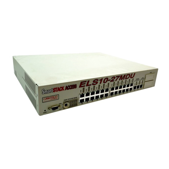
10/100 Mbps ports. The device also features two EPIM- 100 slots that allow the user to install up to two EPIM-100s to provide multimode Þber uplinks (with potential for single mode Þber). It also includes an RS232C port for out-of-band management. ETHERNET SWITCH PORT STATUS MODE STATUS ELS10-27TX... -
Page 21: Smartstack Ethernet Els10-27 Architecture
¥ Provides port trunking to increase bandwidth. ¥ Provides a user selectable monitor port for enhanced troubleshooting. ¥ Supports Auto-negotiation. ¥ Operates in either Half Duplex or Full Duplex modes on all ports. ¥ Implements the Spanning Tree protocol (802.1D). ¥... - Page 22 ¥ Per Ethernet and Fast Ethernet port packet buffer supporting (1,061) 128-byte packets or (88) 1518-byte packets per port. ¥ Per switch packet buffering is (28,672) 128-byte packets and (2,389) 1518-byte packets. Two modes of operation are supported, 802.1D and 802.1Q. These are mutually exclusive.
- Page 23 ¥ IEEE 802.1Q is a standard for virtual bridged local area networks (VLANs). Thirty-two simultaneous VLANs are supported. Support RMON Ethernet Statistics, Alarms, Events, and History group. Network interfaces supported. ¥ All twisted pair copper ports are RJ-45 with internal crossover. ¥...
-
Page 24: Store And Forward Switching
ELS10-27 does not need to learn network topology, requiring less programming and conÞguration time. Store and Forward Switching As an intelligent Ethernet switch, the SmartSTACK Ethernet ELS10-27 uses store and forward switching. Store and forward switching allows the SmartSTACK Ethernet ELS10-27 to temporarily store packets until network resources, typically an unused link, are available for forwarding. -
Page 25: Discarding Local Traffic
Introduction This allows for complete error checking, and limits the amount of time between a device request access to the network, and permission to transmit. In addition, full store and forward switching ensures data integrity; preventing network error conditions from being generated throughout the network. -
Page 26: Spanning Tree Algorithm
Introduction Spanning Tree Algorithm The SmartSTACK Ethernet ELS10-27 supports the IEEE 802.1D Spanning Tree algorithm. The Spanning Tree algorithm converts multiple LANs into a Òspanning treeÓ of networks. It is used to prevent bridging loops. This standard deÞnes a logical (not physical) network conÞguration consisting of one extended LAN without active duplicate paths between spanning tree bridges. -
Page 27: Chapter 5 Smartstack Ethernet
¥ The age of the entry The SmartSTACK Ethernet ELS10-27 database allows for 2048 entries. Some of these entries will be used for permanent entries needed by the switch, and temporary entries dependent on the feature set selected. The remainder will be available for user addresses. -
Page 28: Smartstack Ethernet Els10-27 Sample Applications
With address mirroring, a unicast MAC address and a destination port are speciÞed. Any time a valid packet is received on any port with that destination MAC address within the switch, that packet will be monitored to the destination port. If the address form of the mirror command is issued multiple times, all unicast MAC addresses selected will be mirrored. -
Page 29: Vlans
The operator is able to display the trunking state on each port or enable/disable trunking functionality on a port or a range of ports. 10BASE-T Cables ETHERNET SWITCH PORT STATUS MODE STATUS ELS10-27TX TX ACT... -
Page 30: Ieee 802.1Q Vlans
IEEE 802.1Q is a standard for virtual bridged local area networks (VLANs). It provides an alternate method for forwarding packets through a switch. In an 802.1D (Spanning Tree) bridge, packets are forwarded in accordance with the spanning tree as dynamically created by the 802.1D protocol (Bridge Protocol Data Units (BPDUs), and the... -
Page 31: Configuration Commands
Introduction issue of address translation on a packet that is having the VLAN tag stripped. This only applies to multi-protocol environments, such as a combination of Ethernet, FDDI, and Token Ring protocols and does not apply to the SmartSTACK Ethernet ELS10-27. 802.1Q does NOT replace 802.1D but limits the relaying of packets on the spanning tree to a subset. -
Page 32: Local Console Manager
Introduction GVRP Enable This indicates if the GVRP protocol is selected. If selected, the GVRP application propagates that information to other GVRP applications. GVRP is enabled on a per port basis. GVRP Filter You are able to specify a list of VLAN IDÕs that should not be dynamically learned by GVRP. -
Page 33: Chapter 4 Monitoring And Managing Your Smartstack Ethernet
¥ LCM commands used for conÞguring the SmartSTACK Ethernet ELS10-27 are described in Chapter 3, Configuring Your SmartSTACK Ethernet ELS10-27. ¥ LCM commands used for monitoring and managing the SmartSTACK Ethernet ELS10-27 are described in Chapter 4, Monitoring and Managing Your SmartSTACK Ethernet ELS10-27. Note: The Getting Started with the SmartSTACK Ethernet ELS10-27 guide lists the available LCM commands, including each commandÕs options. -
Page 34: Exit Or Logout
Introduction Exit or Logout This command logs you out of LCM. (The equivalent to the logout Traplog Traplog displays the traps messages captured by the SmartSTACK Ethernet ELS10-27. The following is an example of a traplog display: ELS10-27TX> traplog Trap 16 0:00:00 The unit has booted. - Page 35 The following conventions apply as you use LCM commands: ¥ Press the Enter key to execute a command after you type it in. ¥ A port range is either a single port number, or a list of port numbers separated by commas or hyphens. For example, ports 7;...
-
Page 36: Lcm Command Summary
SECONDS to display routing table information to display current LCM sessions to set or display switch parameters to set or display st age time to print the route taken to a host to set or display traps control value... - Page 37 If a line contains the text Ò[? for syntax]Ó one of the following displays will detail the syntax. additional command syntax: switch [802.1d | 802.1Q] cut[-through] | store[-and-forward] [back[pressure] {on | off}] enable [PORT-RANGE [RIP]] [TransmitPacing]]] port [PORT-RANGE [speed {auto | 10[Mbps] | 100[Mbps]}]...
- Page 38 Introduction Status When the status command alone is typed, the following is displayed: ELS10-27> status Software Currently Running: Version 1.00.00 Mon 1/15/99--14:49:29 Next Bootstrap: Version 1.00.00 Mon 1/15/99--14:49:29 Power-up test failures: none System Up Time: 4 weeks 3 days, 16:49:20 Current Number of Learned Addresses: 76 CPU utilization is heavy Port...
- Page 39 GVRP Port Mirroring: Duplex Mode: Bridging: Enabled/Disabled: Spanning Tree: Trunking State: Pkts Transmitted: Pkts Received: Carrier Losses: Total Collisions: Excess Collisions: RX Filtered Pkts: RX Runt Pkts: RX FCS/Align Errs: Internal TX Errs: Type <CR> to display port 2 status ... > If the status command is issued followed by a port number the following is displayed.
- Page 40 Introduction Carrier Losses: Total Collisions: Excess Collisions: RX Filtered Pkts: RX Runt Pkts: RX FCS/Align Errs: Internal TX Errs: Enable If the enable command is typed without any parameters, the following is displayed. It does not enable any of the ports. ELS10-27>...
- Page 41 If a port range is included, the following is displayed and the ports are disabled. ELS10-27> disable 5-6 Port 5: Disabled Port 6: Disabled Switch The switch command, switch [802.1d | 802.1Q] [cut[-through] | store[-and-forward]] [back[pressure] {on | off}] allows you to select the mode in which the ELS10-27 operates. The two modes are 802.1D (spanning tree) or 802.1Q (spanning tree with IEEE...
- Page 42 Backpressure off The command by itself displays the following: ELS10-27>switch The present switch mode is: 802.1d The switch mode upon the next reboot will be: 802.1d The forwarding mode in use is: Store and Forward Backpressure is off Port The Port command,...
- Page 43 The access option speciÞes when operating in 802.1Q mode, that these ports act as access ports. All devices attached to this segment are non-tag aware devices, Therefore, all tags are stripped on egress, and the default tag is always added on ingress. In addition, the Þrmware creates additional address database entries when needed to ensure connectivity without ßooding.
- Page 44 Introduction To set the storm protection, enter the following: ELS10-27>port 1 storm 100000 10 port 1 threshold = 100000, interval = 10 To set the default VLAN ID the following would be entered. In 802.1Q mode, the factory default would be a value of 0x001 on every port. ELS10-27>port 5 vlan 0x003 port 5 vlan id = 0x003 Commands cannot be combined.
- Page 45 Diagnostic data: Last Image File name Last Server IP Address Flash Size Boot Revision Operational Status Exit or Logout Either of these commands logs you out of LCM. Erase The erase command allows you to erase all of the conÞguration material and restore the factory defaults to the unit.
-
Page 46: Address Display
Introduction reboot [SECONDS [down[load]] | off] [par[ameters] PATH [IP-ADDR [GATEWAY-ADDR]]] If you enter a reboot command, the following is displayed: ELS10-27>reboot 300 Re-boot pending in 300 seconds If you then follow this with the reboot ÔoffÕ command within 300 seconds, the following is displayed: ELS10-27>reboot off No re-boot pending... - Page 47 08:00:20:72:0b:1d Learned 08:00:09:56:01:fe Learned 00:00:c0:aa:08:0e Learned 00:04:ac:26:bd:8b Learned 08:00:69:07:19:a8 Learned 00:a0:c9:37:eb:17 Learned 00:00:1d:1a:80:d7 Learned 00:00:c0:1a:7a:0e Learned Enter <CR> to continue, Cntl-C to exit: Optionally, you can specify the ÔanyÕ option. This will also display any permanent addresses that are conÞgured and any entries that have been created for Þltering.
- Page 48 Introduction 01:80:c2:00:00:0e 01:80:c2:00:00:0f 01:80:c2:00:00:10 01:40:27:00:54:72 00:00:1d:66:88:4e 01:00:0e:00:00:01 Enter <CR> to continue, Cntl-C to exit: If desired, you can specify a MAC address to be searched for and optionally a mask. ELS10-27> address display 08:00:20:79:fb:df Address 08:00:20:79:fb:df Bridge The bridge command allows you to specify whether transparent bridging (Spanning Tree) should be enabled on a per port basis.
- Page 49 Port 10 bridging: Port 11 bridging: Port 12 bridging: Type <CR> to continue the display ... > Optionally, you can select to turn transparent bridging off, or not to send BPDUs out of a group of ports. ELS10-27> bridge 9-10 off Port 9 bridging: Port 10 bridging: ELS10-27>...
- Page 50 Introduction Ipaddr The Ipaddr (IP Address) command is used to conÞgure an IP address for the unit. Optionally, a gateway address is conÞgured to act as a default path in the event that a path to the peer cannot be determined. Refer to the Route Command to conÞgure a gateway.
- Page 51 Route The route command allows you to display routing entries. Only one static route entry can be conÞgured; the default gateway. route display [IPADDR][[GATE[WAY-ADDR]] IPADDR] ELS10-27> route Gateway 134.141.110.14 Destination Next Hop 000.000.000.000 134.141.109.018 100.000.000.000 134.141.105.153 101.000.000.000 134.141.105.155 102.000.000.000 134.141.105.153 103.000.000.000 134.141.105.154 134.141.000.000...
- Page 52 Introduction Ping The ping command allows you to attempt to contact a device using a particular IP address. The HOST parameter is actually an IP Address. Host name to IP address mapping is not available. The command operates in a manner similar to the ping command on an UNIX operating system and is useful in determining connectivity in the network.
- Page 53 When the traceroute command itself is used, the usage statement is displayed. ELS10-27>traceroute ? traceroute [-m max_hops] [-q nqueries] [-w wait] host_ip [data_size] The following is a sample traceroute: ELS10-27> traceroute 192.168.37.20 traceroute to (192.168.37.20), 30 hops max, 40 byte packets 1 134.141.109.18 6 ms 91 ms 99 ms 2 192.168.37.20 99 ms 99 ms 99 ms Traplog...
- Page 54 NOT be changed. Refer to the port command to change the default VLAN ID for a port. If the restriction option is speciÞed, the switch will not allow a VLAN to be established for that ID from either a user interface or GVRP.
- Page 55 Note: Workgroups are only valid in 802.1D mode. ELS10-27> workgroup [NAME [del[ete] | PORT_RANGE]] To display all of the present workgroups, simply enter the command. ELS10-27>workgroup Name: default Port: 8,10,13-27 Name: lab_e Port: 9,12 Name: lab_a Port: 9,11 To display a particular workgroup specify the name. ELS10-27>workgroup lab_a Name: lab_a...
- Page 56 Introduction IPMRouter You can enter the following command to specify the ports to be included in all IP Multicast Þlters. These are expected IGMP Router ports that would be sending IGMP Queries. The command is also used to add non- IGMP capable ports so that they would also be included in all the Þlters.
- Page 57 Display the state of Dynamic IP Multicast Filtering and all the IP Multicast Group entries by entering the command by itself. ELS10-27> ipmulticast Dynamic IP Multicast Þltering is ON GroupAddress 224.0.0.1 224.0.0.9 224.0.0.200 Ipmfilter The ipmÞlter command is used to Þlter IP Multicast packets from a particular port.
- Page 58 Introduction IP Multicast Þltering is ON GroupAddress Ports 224.0.0.24 1-27 224.0.0.9 224.0.0.200 1, 9, 13 Query Use the following command to enable or disable the device to act as a querier. In an 802.1D Workgroup environment, you may specify the name of the workgroup on which to initiate IGMP Queries.
- Page 59 By entering the command alone, the present mirror selections are displayed. ELS10-27>mirror port 5 is being mirrored to port 25. ELS10-27>mirror The mirror port is 7 02:98:10:03:10:09 98:45:82:94:54:76 Trunk The command has the following format: ELS10-27>trunk [PORT-RANGE {on | off}] You are able to enable/disable trunking functionality on a port or a range of ports.
-
Page 60: Trap Control
Introduction Trap control Trap control gives you the ability to allow all traps or to disallow all traps. SNMP MIB variables are available to disable a particular trap, or all traps of a particular severity. The default for trap control is ÒdisabledÓ. Telnet Telnet support allows you to telnet to the device and gain access to LCM. -
Page 61: Chapter 2 Unpacking And Installing Your Smartstack Ethernet Els10-27
UNPACKING AND INSTALLING YOUR SMARTSTACK ETHERNET ELS10-27 Only qualified personnel should perform installation procedures. Carefully unpack the SmartSTACK Ethernet ELS10-27 from the shipping carton and inspect it for possible damage. If any damage is evident, contact your supplier. The shipping carton contains the following: ¥... -
Page 62: Smartstack Ethernet Els10-27 Front Panel
EPIM-100s to provide multimode Þber uplinks (with potential for single mode Þber). Figure 2-1 shows the front panel of the SmartSTACK Ethernet ELS10-27. The LEDs and buttons are described in Tables 2-1 and 2-2. Reset Switch ETHERNET SWITCH PORT STATUS MODE STATUS... - Page 63 Unpacking and Installing Your SmartSTACK Ethernet ELS10-27 Table 2-1. Meaning of SmartSTACK Ethernet ELS10-27 LEDs Port Status Mode On Ð Indicates port is transmitting a packet. On Ð Indicates port is receiving a packet. On Ð Indicates port is transmitting or receiving. On Ð...
-
Page 64: Indicators
Unpacking and Installing Your SmartSTACK Ethernet ELS10-27 Table 2-2. Description of SmartSTACK Ethernet ELS10-27 Buttons Button Status Cycles through the Segment Status options (TX, RX, Act, Col, FDX, 100, MON, and Usr) for all ports. The right-hand port status LEDs of the ports you are monitoring are activated based on what function you chose with the Select button. -
Page 65: System Leds
Unpacking and Installing Your SmartSTACK Ethernet ELS10-27 Monitor Port LED Operation When the port status indicator is selected to ÒMONÓ the following deÞnes the operation of the LEDs for ports that are being mirrored. For ports that have trafÞc mirrored to the monitor port, the LED is on solid. -
Page 66: Installing The Smartstack Ethernet Els10-27
Unpacking and Installing Your SmartSTACK Ethernet ELS10-27 10BASE-T/100BASE-TX Note: Installing an EPIM replaces one of the 100TX ports. 2.3 INSTALLING THE SMARTSTACK ETHERNET ELS10-27 Rack-mounting a SmartSTACK Ethernet ELS10-27 Table 2-3 describes some general considerations you should be aware of before mounting a SmartSTACK Ethernet ELS10-27 in a rack assembly. - Page 67 19-inch equipment cabinet. To mount the SmartSTACK Ethernet ELS10-27 in a rack assembly, apply the following steps: 1. Attach the rackmount brackets to both sides of the SmartSTACK Ethernet ELS10-27 chassis, as shown in Figure 2-3. ETHERNET SWITCH ELS10-27TX RESET Figure 2-3. Attaching Rackmount Brackets 2.
-
Page 68: Checking The Power-Up Diagnostics Sequence
Unpacking and Installing Your SmartSTACK Ethernet ELS10-27 3. Secure the SmartSTACK Ethernet ELS10-27 with the rackmount fasteners by inserting and securing a fastener through each of the four slots in the rack-mount brackets, as shown in Figure 2-4. ETHERNET SWITCH PORT STATUS MODE STATUS ELS10-27TX... -
Page 69: Connecting The Local Console Manager
Unpacking and Installing Your SmartSTACK Ethernet ELS10-27 4. All Segment Status LEDs remain on. 5. All remaining LEDs turn on for several seconds. 6. All LEDs turn OFF, leaving the PWR and CPU LEDs ON. 7. In addition, the Port Link LEDs will turn on for those ports with good links and the Segment Status LEDs will turn on (or ßash) when the selected status condition is present. -
Page 70: Connecting To The Network
Unpacking and Installing Your SmartSTACK Ethernet ELS10-27 2.6 CONNECTING TO THE NETWORK This section provides the procedures for connecting UTP and multimode Þber optic segments from the network or other devices to the SmartSTACK Ethernet ELS10-27. Ports 1 through 24 have RJ45 connectors for UTP connections. Ports 25-27 support FE-100TX UTP connections, with ports 26 and 27 being transferable to optional EPIM100-FX Fast Ethernet Interface Modules. - Page 71 Unpacking and Installing Your SmartSTACK Ethernet ELS10-27 Figure 2-5. SmartSTACK Ethernet ELS10-27 Twisted Pair Connection 3. Verify that a Link exists by checking that the port LINK LED is on (solid green). If the LINK LED is off, perform the following steps until it is on: a.
-
Page 72: Connecting A Multimode Segment To The Epim100-Fx
Unpacking and Installing Your SmartSTACK Ethernet ELS10-27 2.6.2 Connecting a Multimode Segment to the EPIM100-FX The EPIM100-FX has an SC style network port (see Figure 2-8). Cabletron Systems supplies Þber optic cable that uses SC style connectors that are keyed to ensure proper crossing over of the transmit and receive Þbers. Caution: An odd number of crossovers (preferably one) must be maintained between devices so that the transmit port of one device is connected to the receive port of the other device and vice versa. - Page 73 Unpacking and Installing Your SmartSTACK Ethernet ELS10-27 10BASE-T/100BASE-TX 4. Verify that a Link exists by checking that the port LINK LED is solid green. If the LINK LED is off, perform the following steps until it is a. Check that the power is turned on for the device at the other end of the Link.
- Page 74 Unpacking and Installing Your SmartSTACK Ethernet ELS10-27 2-14...
-
Page 75: Chapter 3 Configuring Your Smartstack Ethernet Els10-27
SMARTSTACK ETHERNET ELS10-27 The SmartSTACK Ethernet ELS10-27 does not require any additional conÞguration to operate as a standard, transparent switch. However, if you want to use any of the SmartSTACK Ethernet ELS10-27Õs advanced functions, you must Þrst assign an IP (Internet Protocol) address on the SmartSTACK Ethernet ELS10-27 to communicate with a Simple Network Management Protocol (SNMP) manager. -
Page 76: Assigning Ip Addresses
Configuring Your SmartSTACK Ethernet ELS10-27 ¥ Assigning a community name Note: You can use the LCM information and return the unit to default settings on the next system reset. If you are using a network management tool other than LCM, refer to its accompanying documentation. - Page 77 Configuring Your SmartSTACK Ethernet ELS10-27 User Interfaces (Telnet) If the IP address is modiÞed via Telnet you are prompted to ensure this change is desired. If this mechanism is used to make the change, the change will not take affect until the next reboot. In 802.1d mode the SmartSTACK Ethernet ELS10-27 allows for a single IP address set for the entire device.
-
Page 78: Displaying Ip Addresses
Configuring Your SmartSTACK Ethernet ELS10-27 BOOTP is not supported in 802.1Q mode. If the system is running in 802.1Q mode, and a reboot of the unit takes place, the unit begins operating from Flash Boot sectors. While in Flash Boot sectors, the BOOTP function will not tag packets. -
Page 79: Deleting An Ip Address
00:00:c0:aa:08:0e Learned 00:04:ac:26:bd:8b Learned 08:00:69:07:19:a8 Learned 00:a0:c9:37:eb:17 Learned 00:00:1d:1a:80:d7 Learned 00:00:c0:1a:7a:0e Learned Enter <CR> to continue, Cntl-C to exit: 3.1.3 Deleting an IP Address To delete an IP address, at the LCM prompt: Type ipaddr 0.0.0.0 LCM responds by redisplaying the current IP address table. 3.1.4 Changing a Subnet Mask You can optionally set the subnet mask. -
Page 80: Operational Image
Configuring Your SmartSTACK Ethernet ELS10-27 3.2 OPERATIONAL IMAGE SmartSTACK Ethernet ELS10-27 supports the in-band TFTP loading of Þrmware images. The method for downloading Þrmware into ßash is an Òon-lineÓ download method. Functionality of the download process is supported by the ctdownload mib. On-line download means that the operation of the device is not affected by the downloading process. -
Page 81: Igmp
IDENT Command The IDENT command is enhanced to support displaying the following variables: Part Number: Power-up test code: Diagnostic data: Last Image File Name Last Server IP Address Flash Size Boot Revision Tephra Revision Operational Status Error String 3.3 IGMP The Internet Group Management Protocol allows the establishment of IP multicast groups. - Page 82 Configuring Your SmartSTACK Ethernet ELS10-27 routing protocols to determine their location and adjust the Þlters accordingly. When subsequent queries are heard by the CPU, the CPU notes if any response is heard for each group. A count is kept for each group indicating the number of times a query was heard and there was no response received.
-
Page 83: Enabling Bridging
3.4 ENABLING BRIDGING The LCM command allows you to set bridging options for a single bridge port or a range of ports. The options include: ¥ off ¥ on (the default with ¥ no BPDU BPDU (Bridge Protocol Data Unit) is a data unit transmitted as part of the IEEE 802.1d Spanning Tree protocol. -
Page 84: Displaying Bridging Functions
Configuring Your SmartSTACK Ethernet ELS10-27 3.6 DISPLAYING BRIDGING FUNCTIONS To display the bridging functions that are enabled for all ports, at the LCM prompt: 1. Type bridge LCM responds with a list of all ports and the bridging function that is enabled. -
Page 85: Trunk Groups
As ports within a Trunk Group become forwarding ports, trafÞc within the Trunk Group is momentarily halted to guarantee the Þrst-in, Þrst-out ordering of the Ethernet packets. Configuring Your SmartSTACK Ethernet ELS10-27 ETHERNET SWITCH PORT STATUS MODE ELS10-27TX STATUS TX ACT... -
Page 86: Disabling Trunking
Configuring Your SmartSTACK Ethernet ELS10-27 Note: The SmartSTACK Ethernet ELS10-27-to-SmartSTACK Ethernet ELS10-27 connections must be point-to-point. There cannot be any other devices on those Ethernets. The ports used for trunking can be in any order. However, both ends of the SmartSTACK Ethernet ELS10-27-to- SmartSTACK Ethernet ELS10-27 connections must have trunking turned on for the ports that are being used for the connections. - Page 87 The display could look like the following: ELS10-27 > status 1 Port 1 Status Type/Speed: Port Mirroring: Duplex Mode: Bridging: Enabled/Disabled: Spanning Tree: Trunking State: Pkts Transmitted: Pkts Received: Carrier Losses: Total Collisions: Excess Collisions: RX Missed pkts: RX Runt pkts: RX FCS/Align Errs: Internal TX Errs: Type <CR>...
-
Page 88: Port Mirroring
Configuring Your SmartSTACK Ethernet ELS10-27 3.10 PORT MIRRORING The mirror command has two forms. One will allow the user to mirror all inbound and outbound trafÞc from one port to another. The second will allow all packets with speciÞc destination MAC addresses to be mirrored to a particular port. - Page 89 ETHERNET SWITCH ELS10-27TX RESET Workgroup A Figure 3-2. Defining Virtual Workgroups The LCM commands used to create the previous conÞguration are as follows: 1. To create workgroup A on ports 3, 4, 5, 13, and 16: SmartSTACK Ethernet ELS10-27 > workgroup A 3-5,13,16...
-
Page 90: Assigning A Community Name
Configuring Your SmartSTACK Ethernet ELS10-27 Port 16 has been assigned to a segment that includes ports that belong to workgroup A and workgroup B. Port 13 connects workgroup A to the router and port 24 connects workgroup B to the router. All packets remain within the workgroup. -
Page 91: Configuring Broadcast/Multicast Storm Protection
3. If one has not been assigned, 4. Enter the new community name. 5. LCM prompts you to verify the new community name by retyping 6. Retype the new community name. 3.13 CONFIGURING BROADCAST/MULTICAST STORM PROTECTION The SmartSTACK Ethernet ELS10-27 provides automatic protection against broadcast/multicast storms. -
Page 92: System Contact
Configuring Your SmartSTACK Ethernet ELS10-27 This section provides several common MIB variables you may want to change. Refer to the SmartSTACK Ethernet ELS10-27MIB Reference Guide for a complete listing and description of MIB variables. Each variable is Þrst described in words, and is then identiÞed in MIB form, for example, els10-27adminGetPass - {els10-27admin 3} Display String line shows the range of values that can be used for the... -
Page 93: Community Names
3.16.2 Community Names The set community name variable (from the Cabletron proprietary MIB), must be initialized with the correct community name passwords. All requests from any SNMP manager contain a community name Þeld. For set requests, the community name must match the set password; otherwise, the request will be rejected by the SmartSTACK Ethernet ELS10-27. - Page 94 Configuring Your SmartSTACK Ethernet ELS10-27 3-20...
-
Page 95: Chapter 4 Monitoring And Managing Your Smartstack Ethernet Els10-27
MONITORING AND MANAGING YOUR SMARTSTACK ETHERNET ELS10-27 Monitoring the SmartSTACK Ethernet ELS10-27 consists of collecting and analyzing statistics and system status information. You can use the Select button on the front panel of the SmartSTACK Ethernet ELS10-27 to monitor segment status on any of the Ethernet ports. Refer to Section 2.1 for a description of the segment status options. -
Page 96: Mib Support
Monitoring and Managing Your SmartSTACK Ethernet ELS10-27 4.2 MIB SUPPORT This section lists the SNMP MIBs supported by SmartSTACK ELS10-27. These MIBs allow the user to conÞgure virtually all features and functions of the product. These MIBs also allow this device to be managed by an SNMP management application. -
Page 97: Rmon High Level Description
Monitoring and Managing Your SmartSTACK Ethernet ELS10-27 ¥ The Alarm Group: The Alarm Group periodically takes statistical samples from variables in the system and compares them to thresholds that have been conÞgured. This group stores conÞguration entries that each deÞne, a variable, polling period, and threshold parameters. ¥... -
Page 98: Rmon Details
Monitoring and Managing Your SmartSTACK Ethernet ELS10-27 As soon as you create a History control group, a timer is set up and the process of collecting statistics begins. Waiting for the system clock to reach a special time does NOT happen. Alarm Group, the Event Group, and the Log Group These three groups work together to take statistical samples and process them. - Page 99 Monitoring and Managing Your SmartSTACK Ethernet ELS10-27 You are, when creating entries in these groups, under no obligation to make sure they are in chronological order. However, to make the output display more readable they should be in chronological order. This means, when the entries for the groups are created or restored they should be made into some type of linked list, so new entries can be placed where they are needed to make a more understandable or readable output.
-
Page 100: Smartstack Ethernet Els10-27 Statistics
Monitoring and Managing Your SmartSTACK Ethernet ELS10-27 Modifying The Number Of Statistic Samples Saved The number of buckets (snapshots) of Ethernet statistics saved is set via an SNMP command. The number may be modiÞed at any time. When the number of buckets reaches the value set, the saved statistics in the oldest bucket associated with this History Control Group entry are replaced by the values of the current statistics. -
Page 101: Gathering Statistics
Monitoring and Managing Your SmartSTACK Ethernet ELS10-27 a dedicated, rather than a shared, network connection. In addition, Ethernet port statistics can help you identify a network device that is the source of numerous multicast packets due to a possible malfunction. 4.4.1 Gathering Statistics For purposes of network management, managed objects must be identiÞed. -
Page 102: Using Lcm To Check Smartstack Ethernet Els10-27
Monitoring and Managing Your SmartSTACK Ethernet ELS10-27 The following statistics are available with SNMP: ¥ The number of non-unicast (multicast and broadcast) and unicast packets received from the port. ¥ The number of bytes in the packets that were forwarded. ¥... - Page 103 Monitoring and Managing Your SmartSTACK Ethernet ELS10-27 LCM displays the following type of information. Software Currently Running: version xx.xx.xx software, Tue 08/23/94 15:0 Next Bootstrap: version xx.xx.xx software Tue 08/23/94 15:03:09 Power-up test failures: none System Up Time: 2:25:57 Current Number of Learned Addresses: 133 CPU utilization is light.
-
Page 104: Displaying Mac Addresses
Monitoring and Managing Your SmartSTACK Ethernet ELS10-27 Port 1 Status Type/Speed: VLAN ID: GVRP: Port Mirroring: Duplex Mode: Bridging: Enabled/Disabled: Spanning Tree: Trunking State: Pkts Transmitted: Pkts Received: Carrier Losses Total Collisions Excess Collisions: RX Missed pkts: RX Runt pkts: RX FCS/Align Errs: Internal TX Errs: Type <CR>... -
Page 105: Dynamic (Learned)
Monitoring and Managing Your SmartSTACK Ethernet ELS10-27 ¥ Type of address, including: ¥ Dynamic (learned) ¥ Ethernet port (for the MAC address of an Ethernet port) ¥ BPDU (the MAC address to which all BPDUs are directed) ¥ Reserved (an address reserved by 802.1d, but not yet assigned) ¥... - Page 106 Monitoring and Managing Your SmartSTACK Ethernet ELS10-27 You can display a range of addresses by using a net mask. This is helpful when determining the status associated with stations containing the same make of Ethernet network interface cards. At the LCM prompt: Type addresses display <MAC-ADDRESS>...
-
Page 107: Displaying Manufacturing Information
Monitoring and Managing Your SmartSTACK Ethernet ELS10-27 4.5.3 Displaying Manufacturing Information command identiÞes SmartSTACK Ethernet ELS10-27 ident manufacturing information, including the part number and any power- up test codes and diagnostic data. To display the manufacturing information, at the LCM prompt: Type ident LCM displays the following type of information:... - Page 108 Monitoring and Managing Your SmartSTACK Ethernet ELS10-27 4-14...
-
Page 109: Chapter 5 Smartstack Ethernet Els10-27
SMARTSTACK ETHERNET ELS10-27 DIAGNOSTICS AND TROUBLESHOOTING The SmartSTACK Ethernet ELS10-27 incorporates built-in diagnostic and testing capabilities which are convenient to use and cause minimal or no disruption to the rest of the operational network. These capabilities are effective for isolating problems within the SmartSTACK Ethernet ELS10-27 unit. -
Page 110: Specific Power-Up Tests
SmartSTACK Ethernet ELS10-27 Diagnostics and Troubleshooting 7. In addition, the Port Link LEDs will turn on for those ports with good links and the Segment Status LEDs will turn on (or ßash) when the selected status condition is present. Note: If a critical component fails diagnostics, the CPU LED will turn off and the SmartSTACK Ethernet ELS10-27 will attempt to reboot. -
Page 111: Status And Activity Indicators
Figure 5-1 shows the SmartSTACK Ethernet ELS10-27 front panel LEDs and buttons. The LEDs and buttons are described in Tables 5-1 and 5-2. Segment Status LEDs ETHERNET SWITCH PORT STATUS MODE STATUS ELS10-27TX... - Page 112 SmartSTACK Ethernet ELS10-27 Diagnostics and Troubleshooting Table 5-1 describes the SmartSTACK Ethernet ELS10-27 LEDs. Table 5-1. Meaning of SmartSTACK Ethernet ELS10-27 LEDs Port Status Mode On Ð Indicates port is transmitting a packet. On Ð Indicates port is receiving a packet. On Ð...
-
Page 113: Troubleshooting
SmartSTACK Ethernet ELS10-27 Diagnostics and Troubleshooting 5.4 TROUBLESHOOTING This section lists several situations that could happen while using the SmartSTACK Ethernet ELS10-27, and suggests appropriate action. Because every situation is potentially unique, the corrective actions suggested here should be considered as guidelines only. 5.5 SMARTSTACK ETHERNET ELS10-27 DOES NOT POWER UP If your SmartSTACK Ethernet ELS10-27 does not power up, check each... -
Page 114: Smartstack Ethernet Els10-27 Does Not Respond To Nms
SmartSTACK Ethernet ELS10-27 Diagnostics and Troubleshooting 5.5.3 SmartSTACK Ethernet ELS10-27 Does Not Respond to NMS ¥ Check the port status using LCM. ¥ Check to see if the Spanning Tree topology is stable using LCM. ¥ Check that a pathway to the SmartSTACK Ethernet ELS10-27 exists. ¥... -
Page 115: Appendix A Technical Specifications
TECHNICAL SPECIFICATIONS A.1 SMARTSTACK ETHERNET ELS10-27 SPECIFICATIONS Physical Height Width Depth Weight Installation options Electrical Input voltage Frequency AC power consumption Connector Ports 24 RJ45 Ethernet ports (MDI-X) 3 RJ45 Fast Ethernet port 1 RS232C port for Local Console Manager (LCM) 2 slots for optional Ethernet Port Interface Module Environmental Requirements Operating temperature... -
Page 116: Address Table Size
SmartSTACK Ethernet ELS10-27 Specifications Diagnostic LEDs Individual port link status Individual port segment status Segment status, specifying: - Transmit activity - Receive activity - Both Transmit and Receive activity - Collision - 100 (Mbps) - Duplex - MON (monitor) - User-deÞned Power (Pwr) Standard Support ¥... -
Page 117: Management Support
Management Support ¥ MIB II, 802.1d, 802.3, and Cabletron Enterprise MIB ¥ Cabletron Systems Local Console Manager (LCM) ¥ Any SNMP-based network management system Regulatory Compliance Safety Electromagnetic Compatibility A.2 SERIAL CABLE PIN ASSIGNMENTS For a PC running a Windows terminal connected to the RS232C Network Management Port on the front panel of the SmartSTACK Ethernet ELS10-27, the following serial cable pin assignments (tables A-1 and A-2) are required to manage the SmartSTACK Ethernet ELS10-27 using the... -
Page 118: 10Base-T Pin Assignments
10BASE-T Pin Assignments Table A-2. DB9 Pin Assignments SmartSTACK Ethernet ELS10-27 RJ45 (female) Pin 1 (Rx) Pin 4 (Tx) Pin 5 (GND) A.3 10BASE-T PIN ASSIGNMENTS An Ethernet twisted-pair link segment requires two pairs of wires. Each wire pair is identiÞed by solid and striped colored wires. For example, one wire in the pair might be red and the other wire, red with white stripes. -
Page 119: Straight-Through Wiring
A.4 STRAIGHT-THROUGH WIRING If the twisted-pair link segment is to join two ports on a switch, and only one of the ports has an internal crossover, the two pairs of wires must be straight-through, as shown in Table A-4. -
Page 120: - 4 - 3 Rule
5 - 4 - 3 Rule Table A-5. Crossover RJ45 Pin Assignments SmartSTACK Ethernet ELS10-27 1 (Rx+) 2 (Rx-) 3 (Tx+) 6 (Tx-) A.6 5 - 4 - 3 RULE Between any two nodes (i.e., PCs or other stations) on the network, there can be: ¥... -
Page 121: Epim-100Fx
A.7 EPIM-100FX The EPIM-100FX shown in Figure E-2 supports Multimode Fiber Optic cabling. The EPIM-100FX is equipped with an SC style connector. Specifications for the EPIM-100FX are listed in Table E-3. 1510_10 Table E-3 Transmitter Power (EPIM-100FX) Cable Type 50/125 µm fiber optic 62.5/125 µm fiber optic 100/140 µm fiber optic The transmitter power levels listed above are peak power levels after... - Page 122 EPIM-100FX...
- Page 123 Numerics 10BASE-T connection 2-10 10BASE-T pin assignments A-4 5 - 4 - 3 rule A-6 802.1D Spanning Tree 3-11 adding IP addresses 3-3 address table dynamic entry 1-11 size A-2 addresses adding IP 3-3 deleting IP 3-5 displaying IP 3-4, 4-12 aging time, defined 3-19 assigning community name 3-16...
- Page 124 Index manufacturing information 4-12 Document Conventions 1-3 dynamic entry Bridge Address Table 1-11 ELS10-27TX Bridge Address Table 1-10 certification A-3 management tools 4-1 power-up diagnostics 5-1 specifications A-1 statistics 4-6 ELS10-27TX diagnostics 5-1 enabling bridging functions 3-9 environmental specifications A-1 EPIM specifications EPIM-100FX A-6 erase configuration 3-2...
- Page 125 power-up LED sequence 2-8, 5-1 power-up diagnostics 2-8, 5-1 results 5-2 specific tests 5-2 rack-mount installation 2-7 Ready LED 2-3 Reset button 2-4, 5-4 Segment Status LED 2-3, 5-4 Select button 2-4, 5-4 serial cable DB-9 (female) A-3 DB-9 (male) A-4 pin assignments A-3 set password, defined 3-19 setting...
- Page 126 Index...
Need help?
Do you have a question about the SmartSTACK ETHERNET ELS10-27 and is the answer not in the manual?
Questions and answers