Table of Contents
Advertisement
Quick Links
Advertisement
Table of Contents

Related Manuals for Cabletron Systems SmartSTACK ELS100-8TXUF2


Summary of Contents for Cabletron Systems SmartSTACK ELS100-8TXUF2
- Page 1 SmartSTACK ELS100-8TXUF2 FAST ETHERNET SWITCH INSTALLATION USER GUIDE 9033029...
-
Page 3: Fcc Notice
Only qualified personnel should perform installation procedures. Cabletron Systems reserves the right to make changes in specifications and other information contained in this document without prior notice. The reader should in all cases consult Cabletron Systems to determine whether any such changes have been made. The hardware, firmware, or software described in this manual is subject to change without notice. -
Page 4: Industry Canada Notice
Notice INDUSTRY CANADA NOTICE This digital apparatus does not exceed the Class A limits for radio noise emissions from digital apparatus set out in the Radio Interference Regulations of the Canadian Department of Communications. Le présent appareil numérique n’émet pas de bruits radioélectriques dépassant les limites applicables aux appareils numériques de la class A prescrites dans le Règlement sur le brouillage radioélectrique édicté... -
Page 5: Program License Agreement
CABLETRON SYSTEMS, INC. PROGRAM LICENSE AGREEMENT IMPORTANT: THIS LICENSE APPLIES FOR USE OF PRODUCT IN THE FOLLOWING GEOGRAPHICAL REGIONS: CANADA MEXICO CENTRAL AMERICA SOUTH AMERICA BEFORE OPENING OR UTILIZING THE ENCLOSED PRODUCT, CAREFULLY READ THIS LICENSE AGREEMENT. This document is an agreement (“Agreement”) between You, the end user, and Cabletron Systems, Inc. - Page 6 Notice If the Program is exported from the United States pursuant to the License Exception TSR under the U.S. Export Administration Regulations, in addition to the restriction on transfer set forth in Sections 1 or 2 of this Agreement, You agree not to (i) reexport or release the Program, the source code for the Program or technology to a national of a country in Country Groups D:1 or E:2 (Albania, Armenia, Azerbaijan, Belarus, Bulgaria, Cambodia, Cuba, Estonia, Georgia, Iraq, Kazakhstan, Kyrgyzstan, Laos, Latvia, Libya, Lithuania, Moldova, North Korea, the People’s Republic of China,...
- Page 7 CABLETRON SYSTEMS SALES AND SERVICE, INC. PROGRAM LICENSE AGREEMENT IMPORTANT: THIS LICENSE APPLIES FOR USE OF PRODUCT IN THE UNITED STATES OF AMERICA AND BY UNITED STATES OF AMERICA GOVERNMENT END USERS. BEFORE OPENING OR UTILIZING THE ENCLOSED PRODUCT, CAREFULLY READ THIS LICENSE AGREEMENT. This document is an agreement (“Agreement”) between You, the end user, and Cabletron Systems Sales and Service, Inc.
- Page 8 Notice If the Program is exported from the United States pursuant to the License Exception TSR under the U.S. Export Administration Regulations, in addition to the restriction on transfer set forth in Sections 1 or 2 of this Agreement, You agree not to (i) reexport or release the Program, the source code for the Program or technology to a national of a country in Country Groups D:1 or E:2 (Albania, Armenia, Azerbaijan, Belarus, Bulgaria, Cambodia, Cuba, Estonia, Georgia, Iraq, Kazakhstan, Kyrgyzstan, Laos, Latvia, Libya, Lithuania, Moldova, North Korea, the People’s Republic of China,...
- Page 9 CABLETRON SYSTEMS LIMITED PROGRAM LICENSE AGREEMENT IMPORTANT: THIS LICENSE APPLIES FOR THE USE OF THE PRODUCT IN THE FOLLOWING GEOGRAPHICAL REGIONS: EUROPE MIDDLE EAST AFRICA ASIA AUSTRALIA PACIFIC RIM BEFORE OPENING OR UTILIZING THE ENCLOSED PRODUCT, CAREFULLY READ THIS LICENSE AGREEMENT. This document is an agreement (“Agreement”) between You, the end user, and Cabletron Systems Limited (“Cabletron”) that sets forth your rights and obligations with respect to the Cabletron software program (“Program”) in the package.
- Page 10 Notice If the Program is exported from the United States pursuant to the License Exception TSR under the U.S. Export Administration Regulations, in addition to the restriction on transfer set forth in Sections 1 or 2 of this Agreement, You agree not to (i) reexport or release the Program, the source code for the Program or technology to a national of a country in Country Groups D:1 or E:2 (Albania, Armenia, Azerbaijan, Belarus, Bulgaria, Cambodia, Cuba, Estonia, Georgia, Iraq, Kazakhstan, Kyrgyzstan, Laos, Latvia, Libya, Lithuania, Moldova, North Korea, the People’s Republic of China,...
-
Page 11: Declaration Of Conformity
DECLARATION OF CONFORMITY Application of Council Directive(s): Manufacturer’s Name: Manufacturer’s Address: European Representative Name: European Representative Address: Conformance to Directive(s)/Product Standards: Equipment Type/Environment: We the undersigned, hereby declare, under our sole responsibility, that the equipment packaged with this notice conforms to the above directives. Manufacturer Mr. - Page 12 Notice 9033029...
-
Page 13: Table Of Contents
Mounting the Switch on a Table or Shelf ......8 Mounting the Switch on a Wall ....... . 9 Powering the Switch . - Page 14 Memory ..........16 Port Specifications .
-
Page 15: Preface
Chapter 2. Installation: Describes the content of your switch shipment, lists site requirements, and provides mounting instructions. Instructions for making connections and powering up the switch are provided as well. Appendix A. Technical Specifications: Provides a list of standards compliance and certifications as well as physical and operational specifications. - Page 16 Appendix B. Flow Control: Describes how the flow control features are used to provide a mechanism for protecting the switch from overload conditions and to keep additional traffic off the network. Appendix C. Acronyms and Abbreviations: Provides definitions for a list of common acronyms and abbreviations used within the user guide and the networking industry.
-
Page 17: Product Overview
The ELS100-8TXUF2 switch can be conveniently mounted on a desk or shelf. LEDs on the front panel provide information about the operating status of the switch. The back panel of the switch contains a connector for an external power adapter that is provided with the switch. -
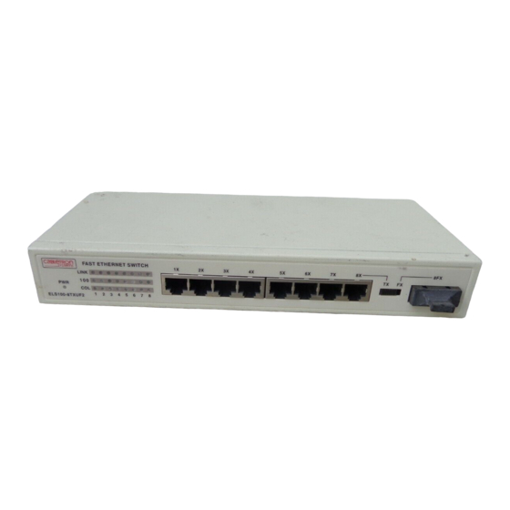
Page 18: Front Panel
100Base-FX Fiber Ports (Port 8)* Ports LEDs Power LED * When using Port 8, use the toggle switch on the front panel to select the RJ-45 con- nector or fiber connector. 2 Product Overview Function Copper port using RJ-45 port connectors. These ports are wired MDI-X. -
Page 19: Rear Panel
Figure 1-2 shows the port Link, Speed and Collision LEDs. The port LEDs are grouped to the left of their corresponding RJ-45 ports. Table 1-2 defines the performance of the port LEDs. Function Link LED On: Indicates a valid connection (link) on the associated port. Off: Indicates no link on the associated port. -
Page 20: Feature Summaries
10Mbps or 100Mbps, and the type of communication setting, half or full duplex. The port is then automatically set by the switch to operate in the proper mode without user intervention. It is not required that the network device being connected to the switch supports auto-negotiation as the ELS100-8TXUF2 switch automatically adjusts to the network device’s... -
Page 21: Leds
A broadcast cutoff threshold rate has been set in the switch for the forwarding of broadcast and unknown destination address packets. If the cutoff rate is exceeded, further packets of these types are dropped. This capability helps to alleviate broadcast storms, a problem often encountered in Ethernet networks. -
Page 22: Client/Server Network Application
10Mbps and 100Mbps speeds, through 10Mbps switches with 100Mbps uplinks, or through direct connections. The fiber uplink is available to connect the switch to a remote location, such as another building floor or a separate building. -
Page 23: Installation
• Rubber feet • Power adapter • This document Site Requirements Before you install the switch, make sure the site meets the following requirements: • Mounting Provide a flat table, wall or shelf surface. • Power source Provide a power source within six feet (1.8 m) of the installation loca- tion. -
Page 24: Mounting The Switch On A Table Or Shelf
First attach the rubber feet to the indentations on the bottom of the switch. Then mount the switch on a table or shelf in a position that allows access to the front panel RJ-45 ports, visibility of the port LEDs, and access to the power cord. -
Page 25: Mounting The Switch On A Wall
The module ships with one (1) velcro strip. the switch to the wall Do not attach rubber feet to the switch when mounting the switch to the wall with velcro. Figure 2-1 illustrates two recommended orientations for wall mounting the switch. -
Page 26: Powering The Switch
Connect the power adapter to the switch and to a grounded three- prong wall outlet (Figure 2-2). Secure the power cord to the tiedown bracket on the back of the switch to prevent it from being accidentally disconnected from the switch. See Appendix A, “Power Adapter Set Requirements,”... -
Page 27: Network Cable Requirements
Network Cable Requirements Copper Table 2-1 specifies the cable types and length constraints for the various copper interfaces on the ELS100-8TXUF2. Table 2-1. Copper Cable Specifications Interface Type 10Base-T 100Base-TX Fiber Table 2-2 specifies the fiber types, bandwidth requirements, and length constraints for the Fast Ethernet fiber interface on the ELS100-8TXUF2. -
Page 28: 10Base-T/100Base-Tx Ports
10Base-T, Section 14 of the IEEE 802.3 specification. The ports are wired with the MDI-X function implemented. Workstations or servers can be connected to the ELS100-8TXUF2 switch using standard straight-through wired cables. For connections to hubs or other switches, a crossover cable may be necessary (refer to the “MDI/MDI-X Crossover Cable Wiring”... -
Page 29: 100Base-Fx Fiber Ports
100Base-FX Fiber Ports The 100Base-FX Fiber port uses SC connectors. Figure 2-4 shows an SC fiber connector being inserted into the fiber port on the ELS100-8TXUF2. Figure 2-4. Inserting a Dual SC Connector into a Port This port supports multi-mode 62.5/125mm fiber. The 100Base-FX port uses SC fiber connectors. - Page 30 14 Installation ELS100-8TXUF2...
-
Page 31: Appendix A. Technical Specifications
APPENDIX A. TECHNICAL SPECIFICATIONS General Standards Compliance IEEE 802.1D Transparent Bridging Specifications (ISO/IEC 10038) IEEE 802.2 Local Area Networks, Logical Link Control (LLC) IEEE 802.3 CSMA/CD 9 (ISO/IEC 8802-3) IEEE 802.3i 10Base-T (ISO/IEC 8802-3, clause 14) IEEE 802.3u 100Base-TX (ISO/IEC 8802-3, clause 25) IEEE 802.3x Flow Control Certification Emissions: FCC Part 15, Subpart B, Class B;... -
Page 32: Physical
Figure A-1 shows the wiring scheme for implementing a crossover cable if needed for connection to the switch’s 10Base-T or 100Base-TX ports. Such a cable may be required when connecting the switch to another switch or a hub device. Figure A-1. External Crossover Cable Wiring 16 Technical Specifications 1.46 in. -
Page 33: Power Adapter Requirements
Power Adapter Requirements Table A-2 shows the power adapter requirements. Table A-2. Power Adapter Requirements Country Adapter P/N USA: 0950-3274 Japan: 0950-3267 Australia: 0950-3269 0950-3270 Europe: T4190800SE * Specifications are shown on the adapter label. 9033029 Input Specifications* 110-127 VAC, 60Hz 90-110 VAC, 50 Hz 230-240 VAC, 50 Hz 220-240 VAC, 50 Hz... - Page 34 18 Technical Specifications ELS100-8TXUF2...
-
Page 35: Appendix B. Flow Control
Figure B-1. Flow Control for Full and Half Duplex Applications Each port of the switch has a transmit queue which buffers frames to be sent out on that port. In this example, large amounts of data are being sent from Workstation A (connected to port X) and other ports on the switch to Workstation B (connected to port Y).The buffer on port Y starts... - Page 36 20 Flow Control ELS100-8TXUF2...
-
Page 37: Appendix C.acronyms And Abbreviations
Institute of Electrical and Electronics Engineers Local Area Network Media Access Control Light Emitting Diode Media Device Interface Media Device Interface-crossover cable wiring Request for Comment Unshielded Twisted Pair A switch that terminates a branch. Also known as a leaf switch. Acronyms and Abbreviations 21... - Page 38 22 Acronyms and Abbreviations ELS100-8TXFU2...
-
Page 39: Index
Port Specifications, 16 Power Adapter Requirements, 17 power cord, 10 power LED, 2 defined, 2 power source, 7 powering the switch, 10 rear panel, 3 RJ-45 connectors, 12 SC fiber connector, 13 site requirements, 7 Spanning Tree, 5 Standards Compliance... - Page 40 24 Index ELS100-8TXUF2...
Need help?
Do you have a question about the SmartSTACK ELS100-8TXUF2 and is the answer not in the manual?
Questions and answers