Table of Contents
Advertisement
Quick Links
Advertisement
Table of Contents
Troubleshooting

Related Manuals for Cabletron Systems SmartSTACK 100


Summary of Contents for Cabletron Systems SmartSTACK 100
-
Page 1: User Guide
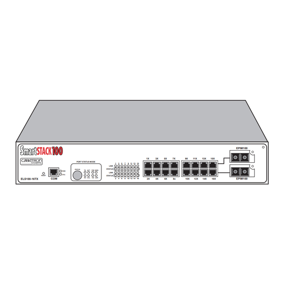
PORT STATUS MODE STATUS RESET ELS100-16TX 9032405-01 SmartSTACK 100 ELS100-16TX USER GUIDE 9 11 13 15 LINK STATUS TX ACT FDX MON LINK STATUS RX COL 100 USR 8 10 12 14 16 EPIM100 EPIM100... -
Page 3: Fcc Notice
Only qualified personnel should perform installation procedures. Cabletron Systems reserves the right to make changes in specifications and other information contained in this document without prior notice. The reader should in all cases consult Cabletron Systems to determine whether any such changes have been made. - Page 4 IMPORTANT: Before utilizing this product, carefully read this License Agreement. This document is an agreement between you, the end user, and Cabletron Systems, Inc. (“Cabletron”) that sets forth your rights and obligations with respect to the Cabletron software program (the “Program”) contained in this package.
- Page 5 Government is subject to restrictions as set forth in subparagraph (c) (1) (ii) of the Rights in Technical Data and Computer Software clause at 252.227-7013. Cabletron Systems, Inc., 35 Industrial Way, Rochester, New Hampshire 03867-0505. Notice...
-
Page 6: Declaration Of Conformity
Principal Compliance Engineer ___________________________________ Title Rochester, NH, USA ___________________________________ Location 89/336/EEC 73/23/EEC Cabletron Systems, Inc. 35 Industrial Way PO Box 5005 Rochester, NH 03867 Mr. J. Solari Cabletron Systems Limited Nexus House, Newbury Business Park London Road, Newbury Berkshire RG13 2PZ, England... -
Page 7: Table Of Contents
1.3 DOCUMENT CONVENTIONS ...1-3 1.4 RELATED DOCUMENTATION ...1-4 1.5 OVERVIEW...1-5 1.5.1 SmartSTACK 100 ELS100-16TX Architecture...1-6 1.5.2 SmartSTACK 100 ELS100-16TX Bridge Address Table...1-11 1.5.3 SmartSTACK 100 ELS100-16TX Port Mirroring...1-12 1.5.4 SmartSTACK 100 ELS100-16TX Sample Applications ...1-12 1.6 LOCAL CONSOLE MANAGER...1-17 1.6.1 Command Syntax Conventions ...1-18 1.6.2 Basic LCM Commands...1-19... - Page 8 Contents 3.10 DISPLAYING MIRRORING STATUS ...3-14 3.11 DEFINING AND DELETING WORKGROUPS ...3-16 3.12 ASSIGNING A COMMUNITY NAME...3-18 3.13 CONFIGURING BROADCAST/MULTICAST STORM PROTECTION ...3-19 3.14 MODIFYING MIB VARIABLES...3-20 3.15 SYSTEM CONTACT ...3-20 3.16 SYSTEM NAME ...3-21 3.16.1 System Location ...3-21 3.16.2 Community Names...3-21 3.16.3 Aging Parameter ...3-22 CHAPTER 4 MONITORING AND MANAGING YOUR ELS100-16TX...
- Page 9 5.2 RESPONSES TO FAILURES AT POWER-UP...5-3 5.3 STATUS AND ACTIVITY INDICATORS ...5-3 5.4 TROUBLESHOOTING ...5-6 5.5 ELS100-16TX DOES NOT POWER UP ...5-6 5.5.1 Connectivity Problems...5-6 5.5.2 ELS100-16TX Has Rebooted ...5-7 5.5.3 ELS100-16TX Does Not Respond to NMS...5-7 APPENDIX A TECHNICAL SPECIFICATIONS A.1 ELS100-16TX Specifications...A-1 A.2 Serial Cable Pin Assignments ...A-3 A.3 100BASE-T Pin Assignments...A-4...
- Page 10 Contents viii...
-
Page 11: Chapter 1 Introduction
• Chapter 2, Unpacking and Installing Your ELS100-16TX, describes the SmartSTACK 100 ELS100-16TX front and rear panels, how to install the SmartSTACK 100 ELS100-16TX, how to connect the Local Console Manager (LCM), and how to connect the ELS100-16TX to the network. -
Page 12: Getting Help
Internet mail Login Password Modem setting For additional information about Cabletron Systems or its products, visit the World Wide Web site: http://www.cabletron.com/ For technical support, select Service and Support. To send comments or suggestions concerning this document, contact the Cabletron Systems Technical Writing Department via the following email address: TechWriting@ctron.com... -
Page 13: Document Conventions
• A description of any action(s) already taken to resolve the problem (e.g., changing mode switches, rebooting the unit, etc.) • The serial and revision numbers of all involved Cabletron Systems products in the network • A description of your network environment (layout, cable type, etc.) •... -
Page 14: Related Documentation
1.4 RELATED DOCUMENTATION The following documentation may assist the user in using this product: • Getting Started with the SmartSTACK 100 ELS100-16TX - contains the basic information for using the SmartSTACK 100 ELS100-16TX. • Interconnections, Bridges and Routers, Radia Perlman, Addison Wesley ©... -
Page 15: Overview
1.5 OVERVIEW The SmartSTACK 100 ELS100-16TX is an intelligent Ethernet-to- Ethernet switch that is configured with 16 IEEE 802.3 10/100BASE-T autosensing Ethernet ports. The SmartSTACK 100 ELS100-16TX provides the option of substituting RJ45 ports 15 and 16 (either or both) with two EPIM ports. These ports accept the EPIM-100FX. -
Page 16: Smartstack 100 Els100-16Tx Architecture
• Implements the Spanning Tree protocol (802.1d). • Configured with factory-set defaults for immediate plug-and- play capability (IP address is not configured at factory). In addition, the SmartSTACK 100 ELS100-16TX offers the following features that can help you manage and maintain your network: •... - Page 17 100 ELS100-16TX reads addresses from the packets it processes, it builds a dynamic database of addresses called the Bridge Address Table. In this way, the SmartSTACK 100 ELS100-16TX continuously learns the addresses of all connected devices. Consequently, you can add new devices to the network, change device addresses, and remove devices from the network without having to reconfigure...
-
Page 18: Port Trunking
SmartSTACK ELS100-16TX and network devices including Cabletron’s SmartStack 10, FastNET products and ATX LAN switch. This capability provides a scalable dedicated bandwidth in a single trunk group of up to 1.6 Gbps (full duplex) when using 100BaseX ports or 160Mbps (full duplex) when using the ports in 10BaseT mode. - Page 19 Introduction ports allowing the switch port and an attached device to negotiate for full or half-duplex modes of operation. The SmartSTACK 100 ELS100-16TX also supports auto-negotiation as defined by IEEE 802.3u and will automatically set the port to the proper mode (10 Mbps, half/full duplex or, 100 Mbps half/full duplex).
- Page 20 LAN without active duplicate paths between spanning tree bridges. The SmartSTACK 100 ELS100-16TX, along with other IEEE 802.1d Spanning Tree compliant bridges in the network, dynamically configure the network topology into a single Spanning Tree by exchanging Bridge Protocol Data Units (BPDUs).
-
Page 21: Smartstack 100 Els100-16Tx Bridge Address Table
ELS100-16TX knows the address and associated segment number the next time it sees that address. By using the information stored in the Bridge Address Table, the SmartSTACK 100 ELS100-16TX is able to quickly forward each packet to the correct LAN segment. -
Page 22: Smartstack 100 Els100-16Tx Port Mirroring
In general, a network backbone allows you to distribute access to important network resources such as file or print servers. Additional SmartSTACK 100 ELS100-16TX features, such as trunking, Fast Ethernet, and virtual workgroups allow you to optimize bandwidth and design a more efficient flow for your network traffic. - Page 23 Introduction SmartSTACK 100 ELS100-16TX Trunking The SmartSTACK 100 ELS100-16TX allows two trunk groups with up to eight ports each to be connected between the SmartSTACK 100 ELS100-16TX and other devices in the FastNetwork and SmartSTACK families. This capability provides a scalable dedicated bandwidth of up to 1.6 Gbps for 100 Mbps ports.
-
Page 24: Virtual Workgroups
RX COL 100 USR ELS100-16TX 100 Mbps Figure 1-4. SmartSTACK 100 ELS100-16TX Trunking with 100 Mbps Ports Virtual Workgroups The SmartSTACK 100 ELS100-16TX allows you to define ports for logical groups of associated devices (virtual workgroups) to provide a more efficient flow of traffic across your Ethernet network. - Page 25 Introduction Figure 1-5 shows two Ethernet segments, A and B, that do not include a SmartSTACK 100 ELS100-16TX. Repeater Traffic Traffic Figure 1-5. Multiple Ethernet Segments Sharing 100 Mbps Bandwidth Each host on segments A and B is limited to sharing a network bandwidth of 10 Mbps.
- Page 26 A and B host. Workgroup A Figure 1-6. Using the SmartSTACK 100 ELS100-16TX to Create Virtual Workgroups to Help Optimize Bandwidth A host from workgroup A can limit a broadcast to all hosts within...
-
Page 27: Local Console Manager
You can also use a Cabletron Systems Network Management System, or a standard SNMP-based Network Management System, to manage the SmartSTACK 100 ELS100-16TX. For a list of available SmartSTACK 100 ELS100-16TX network management tools, see Section 4.1, ELS100-16TX Management Tools. -
Page 28: Command Syntax Conventions
Introduction 1.6.1 Command Syntax Conventions The following conventions apply as you use LCM commands: • Press the Enter key to execute a command after you type it in. • A port range is either a single port number, or a list of port numbers separated by commas or hyphens. -
Page 29: Basic Lcm Commands
Introduction 1.6.2 Basic LCM Commands If you are going to manage the SmartSTACK 100 ELS100-16TX using LCM, you first must connect the SmartSTACK 100 ELS100-16TX to an ASCII terminal or terminal emulator. See Section 2.5, Connecting the Local Console Manager, for instructions. - Page 30 Introduction ELS100-16 > help help or ? status [PORT-RANGE] baud [BAUD-RATE] exit or logout erase ident ipaddr [PORT# IPADDR [MASK]] addresses display [any] [ADDR [MASK]] bridge [PORT-RANGE [OPTIONS]] clearstats trunk [PORT-RANGE [{on|off}]] enable [PORT-RANGE [noRIP]] disable [PORT-RANGE] community sttimer [TIMER-VALUE] workgroup [NAME [delete|PORT-RANGE [INFO]]] speed [PORT-RANGE [{auto|10|100}]] duplex [PORT-RANGE [{auto|half|full}]]...
-
Page 31: Exit Or Logout
Exit or Logout Logs you out of LCM. (The equivalent to the logout Traplog Displays the traps messages captured by the SmartSTACK 100 ELS100-16TX. The following is an example of a traplog display: ELS100-16> traplog Trap 16 0:00:00 The unit has booted. - Page 32 Introduction 1-22...
-
Page 33: Chapter 2 Unpacking And Installing
• Console Cable kit • Two rack-mounting brackets with fasteners (for rack-mount installation) • Documentation – In addition to this manual, the Getting Started with the SmartSTACK 100 ELS100-16TX guide, and Release Notes are also included. Only qualified personnel should perform installation procedures. -
Page 34: Reset Switch
Unpacking and Installing Your ELS100-16TX Reset Switch Status LEDs PORT STATUS MODE STATUS TX ACT RESET RX COL ELS100-16TX Status Button Com Port Figure 2-1. ELS100-16TX Front Panel Port LEDs 9 11 13 15 LINK STATUS FDX MON LINK STATUS... - Page 35 Table 2-1. Meaning of ELS100-16TX LEDs State Port Status Mode Blink Link (Individual Ports) Status (Individual Ports) Blink Unpacking and Installing Your ELS100-16TX Meaning Indicates port is transmitting a packet. Indicates port is receiving a packet. Indicates port is transmitting or receiving.
-
Page 36: Installing An Epim
Unpacking and Installing Your ELS100-16TX Table 2-2 describes the ELS100-16TX buttons. Table 2-2. Description of ELS100-16TX Buttons Button Status Cycles through the Segment Status options (TX, RX, Act, Col, FDX, 100, MON, and Usr) for all ports. The right-hand port status LEDs of the ports you are monitoring are activated based on what function you chose with the Select button. - Page 37 Unpacking and Installing Your ELS100-16TX EPIM100 EPIM100 Figure 2-2. Installing an EPIM EPIM-100FX EPIM-100FX...
-
Page 38: Installing The Els100-16Tx
Unpacking and Installing Your ELS100-16TX 2.3 INSTALLING THE ELS100-16TX Rack-Mounting an ELS100-16TX Table 2-3 describes some general considerations you should be aware of before mounting an ELS100-16TX in a rack assembly. Table 2-3. General Considerations for Mounting an ELS100-16TX Consideration Temperature Air Flow Mechanical Loading... - Page 39 RESET ELS100-16TX Figure 2-3. Attaching Rackmount Brackets 2. Place the ELS100-16TX chassis in the cabinet. 3. Secure the ELS100-16TX with the rackmount fasteners by inserting and securing a fastener through each of the four slots in the rackmount brackets, as shown in Figure 2-4. RESET ELS100-16TX Figure 2-4.
-
Page 40: Checking The Power-Up Diagnostics Sequence
Note: If a critical component fails diagnostics, the CPU LED will turn off and the ELS100-16TX will attempt to reboot. If the CPU LED does not stay on, contact the Cabletron Systems Global Call Center. Refer to Section 1.2. 2.5 CONNECTING THE LOCAL CONSOLE MANAGER The Local Console Manager (LCM) is a command-line interface for configuring, monitoring, and managing the ELS100-16TX through... -
Page 41: Connecting To The Network
To connect the LCM: 1. Connect your ASCII terminal or terminal emulator to the out- of-band management RS232C port on the front panel of the ELS100-16TX using the standard RJ-45 twisted pair cable shipped with the unit. (Only three wires are necessary: Receive Data, Transmit Data and Ground.) 2. -
Page 42: Connecting Utp Cables
Unpacking and Installing Your ELS100-16TX 2.6.1 Connecting UTP Cables Before connecting a segment to the ELS100-16TX, check each end of the segment to verify wire crossover. Caution: To establish a link, you must have an odd number of crossovers (preferably one) between 10/100 BASE-T devices of the same type (i.e., from repeater to repeater or transceiver to transceiver). -
Page 43: Connecting A Segment To The Epim-100Fx
Check that the twisted pair connection meets the dB loss and cable specifications. If a link is not established, contact Cabletron Systems Global Call Center. Refer to Section 1.2, Getting Help, for details. 4. Repeat step 2, above, until all connections have been made. -
Page 44: Fiber Optic Network Connection
Unpacking and Installing Your ELS100-16TX Caution: An odd number of crossovers (preferably one) must be maintained between devices so that the transmit port of one device is connected to the receive port of the other device and vice versa. If the fiber optic cable being used has SC style connectors that do not resemble MIC style connectors, or has SC connectors on one end and a different type on the other, such as ST connectors, ensure that the proper crossing over occurs. -
Page 45: Specifications
Verify that the fiber connection meets the dB loss specifications. If a Link has not been established, contact Cabletron Systems Global Call Center. Refer to Section 1.2, Getting Help, for details. The ELS100-16TX is now ready to be set up through Local Management. - Page 46 Unpacking and Installing Your ELS100-16TX 2-14...
-
Page 47: Chapter 3 Configuring Your Els100-16Tx
CONFIGURING YOUR ELS100-16TX The ELS100-16TX does not require any additional configuration to operate as a standard, transparent switch. However, if you want to use any of the ELS100-16TX advanced functions, you must first assign an IP (Internet Protocol) address to any of the ports on the ELS100-16TX that you use to communicate with a Simple Network Management Protocol (SNMP) manager. -
Page 48: Assigning Ip Addresses
Configuring Your ELS100-16TX The following sections describe how to configure the optional parameters of the ELS100-16TX using LCM commands, including: • Assigning IP addresses • Enabling and disabling bridging • Displaying bridging functions • Enabling and disabling trunking • Displaying trunking status •... - Page 49 • Class B addresses are used for medium sized networks. The first two bytes identify the network and the last two identify the node. The first byte of a class B address must be in the range 128–191. The address 128.150.50.10 identifies node 50.10 on network 128.150.
-
Page 50: Displaying Ip Addresses
Configuring Your ELS100-16TX 3.1.1 Displaying IP Addresses To display IP addresses, subnet masks, and MAC addresses of all ports on the ELS100-16TX you are configuring, at the LCM prompt: 1. Type ipaddr LCM displays the current IP address table, for example: Port IP Address 192.138.217.1... -
Page 51: Enabling Bridging
To change the subnet mask, at the LCM prompt: 1. Type ipaddr <PORT-NUMBER> <IP ADDRESS> <SUBNET MASK> For example, ipaddr 6 192.138.217.40 255.255.240.0 the subnet mask for port 6 to 255.255.240.0. LCM responds by redisplaying the current address table. Note: When you change the subnet mask for a port, you must also enter the IP address for that port. -
Page 52: Disabling Bridging
Configuring Your ELS100-16TX Using LCM to enable bridging for a port or port range, at the LCM prompt: 1. Type bridge [PORT-RANGE [{off|on|noBPDU}]] For example, bridge 2 on LCM responds: Port 2 bridging: Transparent Bridging 3.3 DISABLING BRIDGING To turn off the bridging function for a port or port range, at the LCM prompt: 1. -
Page 53: Enabling Trunking
1.6 Mbps, without installing additional hardware on your network. Trunking is a Cabletron Systems proprietary extension to the 802.1d Spanning Tree algorithm. It enables you to use multiple 100BASE-T Ethernet segments to connect ELS100-16TXs together, while maintaining first-in, first-out ordering of Ethernet packets. -
Page 54: Trunk Groups
Configuring Your ELS100-16TX 100BASE-T Crossover Cables (providing 800 Mbps of bandwidth) Trunk Groups Each set of connections between two ELS100-16TXs is called a Trunk Group. You can create up to eight trunk groups, each with up to eight ports, to interconnect your ELS100-16TXs. For example, if you have three ELS100-16TXs (A, B, and C), as shown in Figure 3-2, you could connect them using a single Ethernet segment. - Page 55 Trunk Group #1 Trunk Group #2 To enable trunking for the example shown, perform the following: 1. Connect the desired ports of the ELS100-16TXs together using 100BASE-T crossover cables. If ELS100-16TX A is handling only a small number of users, the A to B Trunk Group could have just two ports per ELS100- 16TX.
-
Page 56: Disabling Trunking
Configuring Your ELS100-16TX For ELS100-16TX B, at the LCM prompt: b. Type trunk 3-10,14-15 on For ELS100-16TX C, at the LCM prompt: c. Type trunk 3-10 on Each ELS100-16TX determines which ports are part of which Trunk Group. After Trunk Group configuration, the ELS100- 16TXs complete the standard 802.1d Spanning Tree state changes, treating each Trunk Group as a single 802.1d Spanning Tree port. -
Page 57: Displaying Trunking Status
3.7 DISPLAYING TRUNKING STATUS To check the status of your current trunking configuration, at the LCM prompt: 1. Type trunk <PORT-RANGE> The display could look like the following: Note: IP Addresses are not required for trunking to function. ELS100-16 > trunk 2-4 Port 2 trunking joined to Bridge MAC Addr 00:40:27:00:06:1f IP Addr 192.138.217.1 Port 3 trunking joined to Bridge MAC Addr 00:40:27:00:06:c3 IP Addr 192.138.200.2 Port 4 trunking joined to Bridge MAC Addr 00:50:36:00:07:4a IP Addr 192.140.250.7... - Page 58 Configuring Your ELS100-16TX The display could look like the following: ELS100-16 > status 1 Port 1 Status Type/Speed: Port Mirroring: Duplex Mode: Bridging: Enabled/Disabled: Spanning Tree: Trunking State: Pkts Transmitted: Pkts Received: Carrier Losses: Total Collisions: Excess Collisions: RX Missed pkts: RX Runt pkts: RX FCS/Align Errs: Internal TX Errs:...
-
Page 59: Enabling Port Mirroring
• Perturbed — Trunking is enabled, and a good trunk connection has been established. However, the forwarding of data packets is temporarily suspended to allow for a change in the membership of the Trunk Group. 3.8 ENABLING PORT MIRRORING The ELS100-16TX allows you to mirror the 10/100BASE-T ports on the ELS100-16TX. -
Page 60: Displaying Mirroring Status
Configuring Your ELS100-16TX 3.10 DISPLAYING MIRRORING STATUS To check the status of your current mirroring configuration, at the LCM prompt: 1. Type mirror <PORT> The display could look like the following: ELS100-16> mirror 2 Port Mirroring: Port 1 is mirroring Tx traffic Port 16 mirroring off Note: The command will display the status of all ports, even if a... -
Page 61: Receive Packets
To check the status for ports configured for mirroring: 1. Type status <PORT> The display could look like the following: ELS100-16 > status 1 Port 1 Status Type/Speed: Port Mirroring: Duplex Mode: Bridging: Enabled/Disabled: Spanning Tree: Trunking State: Pkts Transmitted: Pkts Received: Carrier Losses: Total Collisions:... -
Page 62: Defining And Deleting Workgroups
Configuring Your ELS100-16TX 3.11 DEFINING AND DELETING WORKGROUPS The ELS100-16TX allows you to define logical groups of associated ports (virtual workgroups) to provide a more efficient flow of traffic across your Ethernet network. Virtual workgroups offer you the ability to limit broadcasts to logical domains within the network. - Page 63 The LCM commands used to create the previous configuration are as follows: 1. To create workgroup A on ports 3, 4, 5, 13, and 16: ESL10-26 > workgroup A 3-5,13,16 LCM responds with the following display: Name: a Ports: 3, 4, 5, 13, 16 Info: All 2.
-
Page 64: Assigning A Community Name
Configuring Your ELS100-16TX To display information about a specific workgroup, at the LCM prompt: 1. Type workgroup NAME To create or modify a workgroup, at the LCM prompt: 1. Type workgroup NAME PORT-RANGE INFO To delete a workgroup, at the LCM prompt: 1. -
Page 65: Configuring Broadcast/Multicast Storm Protection
5. LCM prompts you to verify the new community name by retyping it. 6. Retype the new community name. 3.13 CONFIGURING BROADCAST/MULTICAST STORM PROTECTION The ELS100-16TX provides automatic protection against broadcast/multicast storms. Multicast storms are excessive broadcasts to all ports, typically caused by a malfunctioning device. -
Page 66: Modifying Mib Variables
Configuring Your ELS100-16TX The two Management Information Base (MIB) variables for configuring multicast storm protection are: • – specifies the maximum number of multicasts kxifTxStormCnt that can be broadcast within the given time. • – specifies the period of time that the maximum kxiTxStormTime number of multicasts can be broadcasted. -
Page 67: System Name
3.16 SYSTEM NAME The system name is a name assigned to the ELS100-16TX by the network administrator. By convention, the system name is the fully qualified domain name. (This name then becomes the LCM prompt.) sysName - {system 5} DisplayString (SIZE (0..255)) 3.16.1 System Location The system location identifies the physical location of the ELS100- 16TX. -
Page 68: Aging Parameter
Configuring Your ELS100-16TX Set Community Name The set community name variable ( community name variable ( of the community name used by the SNMP manager for performing either set or get operations. A zero length community name means that any community name is acceptable. kxadminAnyPass - {kxadmin 2} DisplayString (SIZE (0..24)) kxadminGetPass - {kxadmin 2}... -
Page 69: Chapter 4 Monitoring And Managing Your Els100-16Tx
ELS100-16TX through the out-of-band RS232C connection attached to any non-intelligent terminal. You can also use one of the following Cabletron Systems Network Management Stations (NMSs), or a standard SNMP- based NMS to manage the ELS100-16TX: •... -
Page 70: Gathering Statistics
Monitoring and Managing Your ELS100-16TX ELS100-16TX statistics are divided into four groups: • System statistics • Ethernet port statistics • Traffic analysis statistics • SNMP statistics You can use this information to analyze your overall network performance and to make configuration changes as necessary. For example, Ethernet port statistics can help you identify network devices that require high bandwidth, and therefore should be connected through a dedicated, rather than a shared, network... -
Page 71: Ethernet Port Statistics
• The number of spanning tree topology changes that have occurred since the ELS100-16TX was last reset. • The time since a topology change was last initiated. • The physical location of the ELS100-16TX. • The name and address of the contact person for the ELS100- 16TX. -
Page 72: Using Lcm To Check Els100-16Tx Status
Monitoring and Managing Your ELS100-16TX 4.3 USING LCM TO CHECK ELS100-16TX STATUS The LCM commands that enable you to quickly check on the status of the ELS100-16TX include: • Status • Address display • Ipaddr • Ident These LCM commands are described in the sections that follow. 4.3.1 Displaying Status command displays the status of the ELS100-16TX and status... - Page 73 Software Currently Running: version xx.xx.xx software, Tue 08/23/94 15:0 Next Bootstrap (1st bank): version xx.xx.xx software Tue 08/23/94 15:03: Power-up test failures: none System Up Time: 2:25:57 Current Number of Learned Addresses: 133 CPU utilization is light. Port RX Packets 6978 Type <CR>...
-
Page 74: Displaying Mac Addresses
Monitoring and Managing Your ELS100-16TX If you do not want to view the status of port 2, use the Ctrl-C keys to return to the LCM prompt. You can view the status for multiple of ports by typing and indicating the range of port numbers, for example 4.3.2 Displaying MAC Addresses addresses display the ELS100-16TX Bridge Address Table. - Page 75 To display all MAC addresses, at the LCM prompt: 1. Type addresses display any LCM responds with a list of all MAC addresses, their associated ports, the type, age, and number of frames from and to that address. Address Type 08:00:20:02:3a:44 Learned Enter <CR>...
-
Page 76: Displaying Manufacturing Information
Monitoring and Managing Your ELS100-16TX LCM would display: Address 02:04:06:03:2a:43 Learned 02:04:06:00:2a:67 Learned 02:04:06:a3:70:2b Learned Enter <CR> to continue, Ctrl-C to exit: command displays the IP addresses, subnet masks, and ipaddr MAC addresses of all ELS100-16TX ports. At the LCM prompt: 1. -
Page 77: Managing The Els100-16Tx
• Setting the baud rate of your terminal connection • Setting a reboot time You can use the Local Console Manager (LCM), any of the Cabletron Systems NMSs, or a standard SNMP-based NMS to manage the ELS100-16TX. Refer to Section 4.1. 4.5 USING LCM TO MANAGE THE ELS100-16TX... -
Page 78: Disabling A Port
Monitoring and Managing Your ELS100-16TX 4.5.1 Disabling a Port There can be times when you need to disable a specific Ethernet port, for example, after you have determined that there is faulty equipment. Disabling a port effectively stops all bridging functions for that port. -
Page 79: Norip Option
For example, enable 7-9 LCM responds: Port 7: Enabled, Rip listening Port 8: Enabled, Rip listening Port 9: Enabled, Rip listening Note: Rip listening means that the ELS100-16TX is in listening mode only. No RIP packets are created. noRIP Option The Routing Information Protocol (RIP) is one of the protocols that allows the ELS100-16TX to build an accurate, current routing table. -
Page 80: Changing A Community Name
Monitoring and Managing Your ELS100-16TX LCM displays the current IP address table, for example: Port IP Address 192.138.217.1 0.0.0.0 192.138.217.10 0.0.0.0 0.0.0.0 192.138.217.20 192.138.217.50 To change the subnet mask, at the LCM prompt: 1. Type ipaddr <PORT-NUMBER> <IP ADDRESS> <SUBNET MASK> For example, ipaddr 6 192.138.217.40 255.255.240.0 the subnet mask for port 6 to 255.255.240.0. -
Page 81: Setting The Baud Rate
3. Enter the new community name. LCM prompts you to verify the new community name by retyping it. 4. Retype the new community name. 4.5.5 Setting the Baud Rate You can set the baud rate for your LCM console connection. The options for baud rate include: •... -
Page 82: Setting A Reboot Time
Monitoring and Managing Your ELS100-16TX To change the baud rate setting, at the LCM prompt: 1. Type baud <baud rate> For example, baud 9600 LCM responds: 4.5.6 Setting a Reboot Time You can enter the number of seconds the ELS100-16TX waits before rebooting. -
Page 83: Chapter 5 Els100-16Tx Diagnostics And Troubleshooting
ELS100-16TX DIAGNOSTICS AND TROUBLESHOOTING The ELS100-16TX incorporates built-in diagnostic and testing capabilities which are convenient to use and cause minimal or no disruption to the rest of the operational network. These capabilities are effective for isolating problems within the ELS100-16TX unit. Built-in diagnostic capabilities include: •... -
Page 84: Specific Power-Up Tests
Note: If a critical component fails diagnostics, the CPU LED will turn off and the ELS100-16TX will attempt to reboot. If the CPU LED does not stay on, contact Cabletron Systems Global Call Center. Refer to Section 1.2. 5.1.2 Specific Power-up Tests... -
Page 85: Power-Up Diagnostics Results
ELS100-16TX Diagnostics and Troubleshooting 5.1.4 Power-up Diagnostics Results After completion of the power-up diagnostic sequence, both the Power (Pwr) and CPU LEDs located on the front panel of the ELS100-16TX should be on. 5.2 RESPONSES TO FAILURES AT POWER-UP How the ELS100-16TX responds to failures detected during power- up depends on the seriousness of the failure. - Page 86 ELS100-16TX Diagnostics and Troubleshooting Segment Status LEDs PORT STATUS MODE STATUS TX ACT RESET RX COL ELS100-16TX Power and CPU LEDs Segment Status Option Select Button Figure 5-1. ELS100-16TX Front Panel LEDs Port Link LEDs (upper row) 9 11 13 15 LINK STATUS FDX MON...
- Page 87 Table 5-1. Meaning of ELS100-16TX LEDs State Port Status Mode Blink Link (Individual Ports) Status (Individual Ports) Blink ELS100-16TX Diagnostics and Troubleshooting Meaning Indicates port is transmitting a packet. Indicates port is receiving a packet. Indicates port is transmitting or receiving.
-
Page 88: Troubleshooting
ELS100-16TX Diagnostics and Troubleshooting Table 5-2 describes the ELS100-16TX buttons. Table 5-2 Description of ELS100-16TX Buttons Button Status Cycles through the Segment Status options (TX, RX, Act, Col, and Usr) for all ports. The lower port status LEDs of the ports you are monitoring are activated based on what function you chose with the Select button. -
Page 89: Connectivity Problems
• Use the LCM ident diagnostic codes. Write down these codes exactly as they appear and call your authorized Cabletron Systems representative. 5.5.3 ELS100-16TX Does Not Respond to NMS • Check the port status using LCM. • Check to see if the Spanning Tree topology is stable using LCM. - Page 90 ELS100-16TX Diagnostics and Troubleshooting...
-
Page 91: Appendix A Technical Specifications
TECHNICAL SPECIFICATIONS A.1 ELS100-16TX SPECIFICATIONS Physical Height Width Depth Weight Electrical Input voltage Frequency AC power consumption Connector Ports 16 RJ45 Ethernet ports (MDI-X) 1 RS232C port for Local Console Manager (LCM) 2 slots for optional Ethernet Port Interface Module Environmental Operating temperature Storage temperature... - Page 92 Technical Specifications Diagnostic LEDs Individual port link status Individual port segment status Segment status, specifying one of the following: - Transmit activity - Receive activity - Both Transmit and Receive activity - Collision - 100 (Mbps) - Duplex - MON (monitor) - User-defined Power (PWR) Standard Support...
-
Page 93: Serial Cable Pin Assignments
Address Table Size 8,192 dynamic entries Management Support • MIB II, 802.1d, 802.3, and Cabletron Enterprise MIB • Cabletron Systems Local Console Manager (LCM) • Any SNMP-based network management system Regulatory Compliance Safety Electromagnetic Compatibility A.2 SERIAL CABLE PIN ASSIGNMENTS... -
Page 94: 100Base-T Pin Assignments
Technical Specifications Table A-2. DB9 Pin Assignments ELS100-16TX RJ45 (female) Pin 1 (Rx) Pin 4 (Tx) Pin 5 (GND) A.3 100BASE-T PIN ASSIGNMENTS An Ethernet twisted-pair link segment requires two pairs of wires. Each wire pair is identified by solid and striped colored wires. For example, one wire in the pair might be red and the other wire, red with white stripes. -
Page 95: Straight-Through Wiring
A.4 STRAIGHT-THROUGH WIRING If the twisted-pair link segment is to join two ports on a switch, and only one of the ports has an internal crossover, the two pairs of wires must be straight-through, as shown in Table A-4. -
Page 96: The 5 - 4 - 3 Rule
Technical Specifications Table A-5. Crossover RJ45 Pin Assignments ELS100-16TX 1 (Rx+) 2 (Rx-) 3 (Tx+) 6 (Tx-) A.6 THE 5 - 4 - 3 RULE Between any two nodes (i.e., PCs or other stations) on the network, there can be: •... - Page 97 Specifications for the EPIM-100FX are listed in Table A-6. The transmitter power levels and receive sensitivity levels listed are peak power levels after optical overshoot. A peak power meter must be used to correctly compare the values given above to those measured on any particular port.
- Page 98 Technical Specifications...
-
Page 99: Appendix B Glossary
A database of device addresses and their associated ports maintained by a switch or bridge for use in making data packet forwarding and filtering decisions. agent Network management software that runs within a managed network device. - Page 100 Glossary backbone The major, central transmission path for a network. A backbone usually handles high-volume, high-density traffic. Typically a backbone connects various LANs into an integrated network. bandwidth A measure of the amount of traffic a given medium can handle at one time: The communications capacity (measured in bits per second), of a transmission line or of a specific path through a network.
- Page 101 Glossary congestion A condition where a portion of the network is overloaded with more data than can be transmitted in the desired time period. CSMA/CD (carrier-sense multiple access with collision detection) A channel access (contention) method that requires each station to wait for an idle channel before transmitting.
- Page 102 Glossary encapsulation A method for moving messages across networks that use different types of protocols. The message is encapsulated (rather than translated), so it can move across a network that otherwise could not understand its protocol. Encapsulating bridges and switches generally use proprietary encapsulation schemes.
- Page 103 Transition of a device or network from startup state to operational state. intelligent bridge/switch A bridge/switch that is able to identify source and destination addresses. internet A large communications infrastructure composed of wide and local area networks. A generic reference to a network built using internetworking technology.
- Page 104 Glossary internetworking The linking of one or more networks to facilitate communication across networks. interoperability The ability of equipment from multiple vendors to exchange information using standardized protocols. IP (Internet protocol) IP is the basic datagram protocol used at the network layer of the TCP/IP stack.
- Page 105 Specified a subset of a larger set of data to be included for comparison and analysis. For example, in switch filtering, a mask might be configured to include only the first four address bits as the basis for filtering decisions.
- Page 106 Glossary OSI (Open Systems Interconnection) Refers to the OSI reference model, a logical structure for network operations. OSI is the internationally accepted framework of standards for internetwork communication. packet A group of bits including data and control elements arranged in a specific format that are transmitted and switched as a composite whole.
- Page 107 A TCP/IP protocol for communication between a network management system and a network device. source address filtering A switch or bridge function that forwards or rejects data, depending on the data's source address. static address Addresses manually entered into the Bridge Address Table (as opposed to those automatically learned by the ELS100-16TX).
- Page 108 Glossary switch An intelligent, protocol independent device used to connect similar or dissimilar LANs. symbol The smallest signaling element used by the MAC sublayer. Each symbol corresponds to a specific sequence of code bits to be transmitted by the physical layer.
- Page 109 Glossary upstream Refers to the relative position of a station in a network to another station in the same network. A station is upstream from its neighbor if it receives data before its neighbor receives the data. WAN (wide area network) A communication network that spans a large geographic area.
- Page 110 Glossary B-12...
Need help?
Do you have a question about the SmartSTACK 100 and is the answer not in the manual?
Questions and answers