Table of Contents
Advertisement
Quick Links
Advertisement
Table of Contents
Troubleshooting

Related Manuals for Cabletron Systems ELS10-26TX


Summary of Contents for Cabletron Systems ELS10-26TX
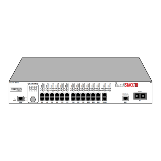
- Page 1 ELS10-26 USER GUIDE ELS10-26TX PORT STATUS MODE TX ACT FDX MON RX COL 100 USR STATUS RESET 9032243-01 SmartSTACK 10 FEPIM 10BASE-T/ 100BASE-TX MONX...
- Page 3 Only qualified personnel should perform installation procedures. Cabletron Systems reserves the right to make changes in specifications and other information contained in this document without prior notice. The reader should in all cases consult Cabletron Systems to determine whether any such changes have been made.
- Page 4 IMPORTANT: Before utilizing this product, carefully read this License Agreement. This document is an agreement between you, the end user, and Cabletron Systems, Inc. (“Cabletron”) that sets forth your rights and obligations with respect to the Cabletron software program (the “Program”) contained in this package.
- Page 5 Government is subject to restrictions as set forth in subparagraph (c) (1) (ii) of the Rights in Technical Data and Computer Software clause at 252.227-7013. Cabletron Systems, Inc., 35 Industrial Way, Rochester, New Hampshire 03867-0505. Notice...
-
Page 6: Declaration Of Conformity
Principal Compliance Engineer ___________________________________ Title Rochester, NH, USA ___________________________________ Location 89/336/EEC 73/23/EEC Cabletron Systems, Inc. 35 Industrial Way PO Box 5005 Rochester, NH 03867 Mr. J. Solari Cabletron Systems Limited Nexus House, Newbury Business Park London Road, Newbury Berkshire RG13 2PZ, England... -
Page 7: Table Of Contents
CHAPTER 1 INTRODUCTION 1.1 ABOUT THIS MANUAL ...1-1 1.2 GETTING HELP...1-2 1.4 RELATED DOCUMENTATION ...1-4 1.5 OVERVIEW...1-4 1.5.1 SmartSTACK 10 ELS10-26 Architecture ...1-6 1.5.2 SmartSTACK 10 ELS10-26 Bridge Address Table...1-9 1.5.3 SmartSTACK 10 ELS10-26 Port Monitoring ...1-10 1.5.4 SmartSTACK 10 ELS10-26 Sample Applications ...1-11 1.6 LOCAL CONSOLE MANAGER...1-18 1.6.1 Command Syntax Conventions ...1-18 1.6.2 Basic LCM Commands...1-20... - Page 8 Contents 3.10 DISPLAYING MONITORING STATUS...3-12 3.11 DEFINING AND DELETING WORKGROUPS ...3-14 3.12 ASSIGNING A COMMUNITY NAME...3-16 3.13 CONFIGURING BROADCAST/MULTICAST STORM PROTECTION ...3-17 3.14 MODIFYING MIB VARIABLES...3-18 3.15 SYSTEM CONTACT ...3-18 3.16 SYSTEM NAME ...3-18 3.16.1 System Location ...3-19 3.16.2 Community Names...3-19 3.16.3 Aging Parameter ...3-19 CHAPTER 4 MONITORING AND MANAGING YOUR ELS10-26...
- Page 9 CHAPTER 5 ELS10-26 DIAGNOSTICS AND TROUBLESHOOTING 5.1 POWER-UP DIAGNOSTICS ...5-1 5.1.1 Power-up LED Sequence ...5-1 5.1.2 Specific Power-up Tests ...5-2 5.1.3 Software Checksum Comparison ...5-2 5.1.4 Power-up Diagnostics Results ...5-3 5.2 RESPONSES TO FAILURES AT POWER-UP...5-3 5.3 STATUS AND ACTIVITY INDICATORS ...5-3 5.4 TROUBLESHOOTING ...5-6 5.5 ELS10-26 DOES NOT POWER UP ...5-6 5.5.1 Connectivity Problems...5-6...
- Page 10 Contents viii...
-
Page 11: Chapter 1 Introduction
1.1 ABOUT THIS MANUAL This manual is for system administrators responsible for configuring, monitoring, and maintaining the SmartSTACK 10 ELS10-26TX. You should have a familiarity with networking concepts and principles. In addition, a basic understanding of SNMP is helpful. Some SmartSTACK 10 ELS10-26 configurations can only be done using an SNMP-based Network Management System (NMS). -
Page 12: Getting Help
SmartSTACK 10 ELS10-26 and common to the networking field. 1.2 GETTING HELP If you need additional support related to the SmartSTACK 10 ELS10-26, or if you have any questions, comments, or suggestions concerning this manual, contact Cabletron Systems Global Call Center: Phone: Internet mail: FTP:... -
Page 13: Document Conventions
• A description of any action(s) already taken to resolve the problem (e.g., changing mode switches, rebooting the unit, etc.) • The serial and revision numbers of all Cabletron Systems products in the network • A description of your network environment (layout, cable type, etc.) -
Page 14: Related Documentation
Introduction and an IP address to execute the command: ELS10-26 >ipaddr 6 192.138.217.40 Field value options appear in bold typeface. The following conventions are also used in this document: Note: Calls the reader’s attention to any item of information that may be of special importance. -
Page 15: Introduction
1.5 OVERVIEW The SmartSTACK 10 ELS10-26TX is an intelligent Ethernet-to- Ethernet switch that is configured with 25 IEEE 802.3 10BASE-T Full Duplex Ethernet ports, one fixed 100BASE-TX copper connection, one port supporting either a copper or fiber 100 Mbps FEPIM (Fast Ethernet Port Interface Module), and one fixed RJ45 for port monitoring of the 10 Mbps ports. -
Page 16: Smartstack 10 Els10-26 Architecture
Introduction • Operates in either Half Duplex or Full Duplex modes on all ports. • Implements the Spanning Tree protocol (802.1d). • Configured with factory-set defaults for immediate plug-and- play capability (IP address is not configured at factory). In addition, the SmartSTACK 10 ELS10-26 offers the following features that can help you manage and maintain your network: •... - Page 17 SmartSTACK 10 ELS10-26 does not need to learn network topology, requiring less programming and configuration time. Store and Forward Switching As an intelligent Ethernet switch, the SmartSTACK 10 ELS10-26 uses store and forward switching. Store and forward switching allows the SmartSTACK 10 ELS10-26 to temporarily store packets until network resources, typically an unused link, are available for forwarding.
- Page 18 Introduction network and when it is granted permission to transmit. In addition, full store and forward switching ensures data integrity, thus preventing network error conditions from being generated throughout the network. Discarding Local Traffic The SmartSTACK 10 ELS10-26 checks all incoming packets for their destination address against the Bridge Address Table.
-
Page 19: Smartstack 10 Els10-26 Bridge Address Table
Introduction By forwarding only packets addressed to devices on other network segments, the SmartSTACK 10 ELS10-26 reduces unnecessary traffic and thereby enhances the overall performance of the network. Note: If the packet address is not found in the Bridge Address Table, it will be forwarded (flooded) to all network segments. - Page 20 Introduction If a packet’s address is not already stored in the Bridge Address Table, the SmartSTACK 10 ELS10-26 adds the learned address, associated segment number, and a timer value indicating the age of the observation. Consequently, the SmartSTACK 10 ELS10-26 knows the address and associated segment number the next time it sees that address.
-
Page 21: Smartstack 10 Els10-26 Port Monitoring
Introduction 1.5.3 SmartSTACK 10 ELS10-26 Port Monitoring Port monitoring allows the SmartSTACK 10 ELS10-26 to redirect network traffic (including MAC layer errors) from one port to the port monitoring port (MONX port), in effect “mirroring” all network traffic to this port. This feature allows users who have existing investments in external analyzers, external RMON probes, or devices like Network General's Distributed Sniffer System continue to receive expert analysis and packet decode functions in... - Page 22 Figure 1-4 illustrates the trunking of multiple SmartSTACK 10 ELS10-26 ports to increase the bandwidth. 10 Mbps ELS10-26TX RESET Up to 80 Mbps Bandwidth ELS10-26TX...
- Page 23 Figure 1-5 illustrates how the SmartSTACK 10 ELS10-26 can be used in a backbone network configuration. 10BASE-T Cables ELS10-26TX PORT STATUS MODE TX ACT FDX MON RX COL 100 USR STATUS RESET Trunk Lines ELS10-26TX PORT STATUS MODE TX ACT...
- Page 24 Introduction Figure 1-6 illustrates connecting two SmartSTACK 10 ELS10-26 Fast Ethernet ports to increase the bandwidth to 200 Mbps. ELS10-26 ELS10-26TX PORT STATUS MODE TX ACT FDX MON RX COL 100 USR STATUS RESET Front Panel ELS10-26 ELS10-26TX PORT STATUS MODE...
-
Page 25: Virtual Workgroups
Figure 1-7 illustrates how the SmartSTACK 10 ELS10-26 can be used in a backbone network configuration using increased bandwidth of the Fast Ethernet configuration. Network Servers Management Station 10BASE-T Cables ELS10-26TX PORT STATUS MODE TX ACT FDX MON RX COL 100 USR STATUS RESET... - Page 26 Introduction Figure 1-8 shows two Ethernet segments, A and B, that do not include a SmartSTACK 10 ELS10-26. Repeater Traffic Traffic Figure 1-8. Multiple Ethernet Segments Sharing 10 Mbps Bandwidth Each host on segments A and B is limited to sharing a network bandwidth of 10 Mbps.
- Page 27 Figure 1-9 shows two Ethernet segments that take advantage of the virtual workgroup feature of the SmartSTACK 10 ELS10-26 and the increased bandwidth applied to each A and B host. ELS10-26TX Workgroup A Figure 1-9. Using the SmartSTACK 10 ELS10-26 to Create Virtual...
-
Page 28: Local Console Manager
RS232C connection attached to any non- intelligent terminal or workstation running terminal emulation. You can also use a Cabletron Systems Network Management System, or a standard SNMP-based Network Management System, to manage the SmartSTACK 10 ELS10-26. For a list of available SmartSTACK 10 ELS10-26 network management tools, see Section 4.1, SmartSTACK 10 ELS10-26 Management Tools. -
Page 29: Command Syntax Conventions
1.6.1 Command Syntax Conventions The following conventions apply as you use LCM commands: • Press the Enter key to execute a command after you type it in. • A port range is either a single port number, or a list of port numbers separated by commas or hyphens. -
Page 30: Basic Lcm Commands
Introduction 1.6.2 Basic LCM Commands If you are going to manage the SmartSTACK 10 ELS10-26 using LCM, you first must connect the SmartSTACK 10 ELS10-26 to an ASCII terminal or terminal emulator. See Section 2.5, Connecting the Local Console Manager, for instructions. When you want to use LCM, begin by pressing the Enter key several times to get the LCM prompt ( ELS10-26 >... - Page 31 ELS10-26 > help help or ? status [PORT-RANGE] baud [BAUD-RATE] exit or logout erase indent ipaddr [PORT# IPADDR [MASK]] addresses display [any] [ADDR [MASK]] bridge [PORT-RANGE [OPTIONS]] clearstats trunk [PORT-RANGE [{on|off}]] enable [PORT-RANGE [noRIP][TransmitPacing]] disable [PORT-RANGE] community sttimer [TIME-VALUE] workgroup [NAME [delete|PORT-RANGE [INFO]]] speed [PORT-RANGE [{auto|10|100}]] duplex [PORT-RANGE [{auto|half|full}]] mirror [PORT# [{Rx|Tx|both|off}]]...
-
Page 32: Exit Or Logout
Traplog Displays the traps messages captured by the SmartSTACK 10 ELS10-26. The following is an example of a traplog display: ELS10-26TX> traplog Trap 16 0:00:00 The unit has booted. Trap 25 0:00:00 The unit’s spanning tree maximum age has changed. -
Page 33: Chapter 2 Unpacking And Installing Your Els10-26
UNPACKING AND INSTALLING Carefully unpack the ELS10-26 from the shipping carton and inspect it for possible damage. If any damage is evident, contact your supplier. The shipping carton contains the following: • The ELS10-26 unit • One AC power cord •... - Page 34 Unpacking and Installing Your ELS10-26 Reset Switch ELS10-26TX RESET Status Button Com Port RJ45 Ethernet 10BASE-T Ports Figure 2-1. ELS10-26 Front Panel Status LEDs PORT STATUS MODE TX ACT FDX MON RX COL 100 USR STATUS Monitor Port 100BASE Ethernet FEPIM Port...
- Page 35 Table 2-1. Meaning of ELS10-26 LEDs Meaning Port Status Mode On – Indicates port is transmitting a packet. On – Indicates port is receiving a packet. On – Indicates port is transmitting or receiving. On – Indicates a collision on a port. On - Port is operating in Full Duplex.
-
Page 36: Installing An Fepim
Unpacking and Installing Your ELS10-26 Table 2-2 describes the ELS10-26 buttons. Table 2-2. Description of ELS10-26 Buttons Button Status Cycles through the Segment Status options (TX, RX, Act, Col, FDX, 100, MON, and Usr) for all ports. The right-hand port status LEDs of the ports you are monitoring are activated based on what function you chose with the Select button. - Page 37 Unpacking and Installing Your ELS10-26 Faceplate Figure 2-2. Installing an FEPIM Module Module Connector Standoff Motherboard Connector Standoffs 1742-39...
-
Page 38: Installing The Els10-26
Unpacking and Installing Your ELS10-26 2.3 INSTALLING THE ELS10-26 Rack-mounting an ELS10-26 Table 2-3 describes some general considerations you should be aware of before mounting a ELS10-26 in a rack assembly. Table 2-3. General Considerations for Mounting an ELS10-26 Consideration Temperature Air Flow Mechanical Loading... - Page 39 To mount the ELS10-26 in a rack assembly, apply the following steps: 1. Attach the rackmount brackets to either side of the ELS10-26 chassis, as shown in Figure 2-3. ELS10-26TX PORT STATUS MODE TX ACT RX COL STATUS RESET Figure 2-3.
-
Page 40: Checking The Power-Up Diagnostics Sequence
flash) when the selected status condition is present. Note: If a critical component fails diagnostics, the CPU LED will turn off and the ELS10-26 will attempt to reboot. If the CPU LED does not stay on, contact Cabletron Systems Global Call Center. Refer to Section 1.2. -
Page 41: Connecting The Local Console Manager
2.5 CONNECTING THE LOCAL CONSOLE MANAGER The Local Console Manager (LCM) is a command-line interface for configuring, monitoring, and managing the ELS10-26 through the out-of-band RS232C connection on the front panel. To connect the LCM: 1. Connect your ASCII terminal or terminal emulator to the out- of-band management RS232C port on the front panel of the ELS10-26 using the standard RJ-45 twisted pair cable shipped with the unit. -
Page 42: Connecting Utp Cables
Unpacking and Installing Your ELS10-26 Refer to Section 2.6.3 to make a fiber optic connection to an FE-100FX. 2.6.1 Connecting UTP Cables Before connecting a segment to the ELS10-26, check each end of the segment to verify wire crossover. Caution: To establish a link, you must have an odd number of crossovers (preferably one) between 10BASE-T devices of the same type (i.e., from repeater to repeater or transceiver to transceiver). -
Page 43: Connecting A Utp Segment To The Fe-100Tx
Check that the twisted pair connection meets the dB loss and cable specifications. If a link is not established, contact Cabletron Systems Global Call Center. Refer to Section 1.2, Getting Help, for details. 4. Repeat step 2, above, until all connections have been made. - Page 44 A schematic of a crossover cable is shown in Figure 2-6. If the wires do not cross over, use the switch on the FE-100TX to internally cross over the RJ45 port. Figure 2-7 shows how to properly set the FE-100TX crossover switch.
-
Page 45: Fiber Optic Network Connection
If a Link is not established, contact Cabletron Systems Global Call Center. Refer to Section 1.2, Getting Help, for details. 2.6.3 Connecting a Multimode Segment to the FE-100FX The FE-100FX has an SC style network port (see Figure 2-8). - Page 46 Unpacking and Installing Your ELS10-26 Caution: Do not touch the ends of the fiber optic strands, and do not let the ends come in contact with dust, dirt, or other contaminants. Contamination of the ends causes problems in data transmissions. If the ends become contaminated, clean them with alcohol using a soft, clean, lint-free cloth.
- Page 47 Verify that the fiber connection meets the dB loss specifications. If a Link has not been established, contact Cabletron Systems Global Call Center. Refer to Section 1.2, Getting Help, for details. The ELS10-26 is now ready to be set up through Local Management.
- Page 48 Unpacking and Installing Your ELS10-26 2-16...
-
Page 49: Chapter 3 Configuring Your Els10-26
CONFIGURING YOUR ELS10-26 The ELS10-26 does not require any additional configuration to operate as a standard, transparent switch. However, if you want to use any of the ELS10-26’s advanced functions, you must first assign an IP (Internet Protocol) address to any of the ports on the ELS10-26 that you use to communicate with a Simple Network Management Protocol (SNMP) manager. -
Page 50: Assigning Ip Addresses
Configuring Your ELS10-26 The following sections describe how to configure the optional parameters of the ELS10-26 using LCM commands, including: • Assigning IP addresses • Enabling and disabling bridging • Displaying bridging functions • Enabling and disabling trunking • Displaying trunking status •... - Page 51 • Class B addresses are used for medium sized networks. The first two bytes identify the network and the last two identify the node. The first byte of a class B address must be in the range 128- 191. The address 128.150.50.10 identifies node 50.10 on network 128.150.
-
Page 52: Displaying Ip Addresses
Configuring Your ELS10-26 3.1.1 Displaying IP Addresses To display IP addresses, subnet masks, and MAC addresses of all ports on the ELS10-26 you are configuring, at the LCM prompt: 1. Type ipaddr LCM displays the current IP address table, for example: Port IP Address 192.138.217.1... -
Page 53: Enabling Bridging
To change the subnet mask, at the LCM prompt: 1. Type ipaddr <PORT-NUMBER> <IP ADDRESS> <SUBNET MASK> For example, ipaddr 6 192.138.217.40 255.255.240.0 the subnet mask for port 6 to 255.255.240.0. LCM responds by redisplaying the current address table. Note: When you change the subnet mask for a port, you must also enter the IP address for that port. -
Page 54: Disabling Bridging
Configuring Your ELS10-26 Using LCM to enable bridging for a port or port range, at the LCM prompt: 1. Type bridge [PORT-RANGE [{off|on|noBPDU}]] For example, bridge 2 on LCM responds: Port 2 bridging: Transparent Bridging 3.3 DISABLING BRIDGING To turn off the bridging function for a port or port range, at the LCM prompt: 1. -
Page 55: Enabling Trunking
160 Mbps, or 400 Mbps using 100Base ports, without installing additional hardware on your network. Trunking is a Cabletron Systems proprietary extension to the 802.1D Spanning Tree algorithm. It enables you to use multiple 10BASE-T Ethernet segments to connect ELS10-26s together, while maintaining first-in, first-out ordering of Ethernet packets. -
Page 56: Trunk Groups
However, that would limit the interconnection to 10 Mbps. To solve this problem, you could connect A to B with one Trunk Group, and connect B to C with a second Trunk Group. ELS10-26TX PORT STATUS MODE TX ACT... - Page 57 2. Using LCM or a NMS, turn on trunking for the connected ports on each ELS10-26. For ELS10-26 A, at the LCM prompt: a. Type trunk 2,3 on ELS10-26TX PORT STATUS MODE TX ACT FDX MON RX COL 100 USR...
-
Page 58: Disabling Trunking
Configuring Your ELS10-26 For ELS10-26 B, at the LCM prompt: b. Type trunk 3-10,14-15 on For ELS10-26 C, at the LCM prompt: c. Type trunk 3-10 on Each ELS10-26 determines which ports are part of which Trunk Group. After Trunk Group configuration, the ELS10-26s complete the standard 802.1D Spanning Tree state changes, treating each Trunk Group as a single 802.1D Spanning Tree port. -
Page 59: Displaying Trunking Status
3.7 DISPLAYING TRUNKING STATUS To check the status of your current trunking configuration, at the LCM prompt: 1. Type trunk <PORT-RANGE> The display could look like the following: Note: IP Addresses are not required for trunking to function. ELS10-26 > trunk 2-4 Port 2 trunking joined to Bridge MAC Addr 00:40:27:00:06:1f IP Addr 192.138.217.1 Port 3 trunking joined to Bridge MAC Addr 00:40:27:00:06:c3 IP Addr 192.138.200.2 Port 4 trunking joined to Bridge MAC Addr 00:50:36:00:07:4a IP Addr 192.140.250.7... - Page 60 Configuring Your ELS10-26 The display could look like the following: ELS10-26 > status 1 Port 1 Status Type/Speed: Port Mirroring: Duplex Mode: Bridging: Enabled/Disabled: Spanning Tree: Trunking State: Pkts Transmitted: Pkts Received: Carrier Losses: Total Collisions: Excess Collisions: RX Missed pkts: RX Runt pkts: RX FCS/Align Errs: Internal TX Errs:...
-
Page 61: Enabling Port Monitoring
• Perturbed — Trunking is enabled, and a good trunk connection has been established. However, the forwarding of data packets is temporarily suspended to allow for a change in the membership of the Trunk Group. 3.8 ENABLING PORT MONITORING The ELS10-26 allows you to monitor the 10BASE-T ports on the ELS10-26 (you cannot monitor the 100BASE ports ). -
Page 62: Disabling Monitoring
Configuring Your ELS10-26 3.9 DISABLING MONITORING To turn off monitoring, at the LCM prompt: 1. Type Mirror <PORT> off For example, mirror 2 off 3.10 DISPLAYING MONITORING STATUS To check the status of your current monitoring configuration, at the LCM prompt: 1. - Page 63 The display could look like the following: ELS10-26 > status 1 Port 1 Status Type/Speed: Port Mirroring: Duplex Mode: Bridging: Enabled/Disabled: Spanning Tree: Trunking State: Pkts Transmitted: Pkts Received: Carrier Losses: Total Collisions: Excess Collisions: RX Missed pkts: RX Runt pkts: RX FCS/Align Errs: Internal TX Errs: Type <CR>...
-
Page 64: Defining And Deleting Workgroups
A and B. Workgroup A uses ports 3 through 5,13 and 16 and workgroup B uses ports 7, 11, 16 and 24. Port 16 connects a segment that contains both workgroup A and workgroup B hosts. ELS10-26TX Workgroup A Figure 3-3. Defining Virtual Workgroups 3-16... - Page 65 The LCM commands used to create the previous configuration are as follows: 1. To create workgroup A on ports 3, 4, 5, 13, and 16: ESL10-26 > workgroup A 3-5,13,16 LCM responds with the following display: Name: a Ports: 3, 4, 5, 13, 16 Info: all 2.
-
Page 66: Assigning A Community Name
Configuring Your ELS10-26 To display information about a specific workgroup, at the LCM prompt: 1. Type workgroup NAME To create or modify a workgroup, at the LCM prompt: 1. Type workgroup NAME PORT-RANGE INFO To delete a workgroup, at the LCM prompt: 1. -
Page 67: Configuring Broadcast/Multicast Storm Protection
5. LCM prompts you to verify the new community name by retyping it. 6. Retype the new community name. 3.13 CONFIGURING BROADCAST/MULTICAST STORM PROTECTION The ELS10-26 provides automatic protection against broadcast/multicast storms. Multicast storms are excessive broadcasts to all ports, typically caused by a malfunctioning device. -
Page 68: Modifying Mib Variables
Configuring Your ELS10-26 • – specifies the maximum number of multicasts lxifTxStormCnt that can be broadcast within the given time. • – specifies the period of time that the maximum lxiTxStormTime number of multicasts can be broadcasted. Refer to the ELS10-26 MIB Reference Guide for a complete listing and description of MIB variables. -
Page 69: System Name
3.16 SYSTEM NAME The system name is a name assigned to the ELS10-26 by the network administrator. By convention, the system name is the fully qualified domain name. (This name then becomes the LCM prompt.) sysName - {system 5} DisplayString (SIZE (0..255)) 3.16.1 System Location The system location identifies the physical location of the ELS10- sysLocation - {system 6}... -
Page 70: Aging Parameter
Configuring Your ELS10-26 Set Community Name The set community name variable ( community name variable ( of the community name used by the SNMP manager for performing either set or get operations. A zero length community name means that any community name is acceptable. lxadminAnyPass - {lxadmin 2} DisplayString (SIZE (0..24)) lxadminGetPass - {lxadmin 2}... -
Page 71: Chapter 4 Monitoring And Managing Your Els10-26
ELS10-26 through the out- of-band RS232C connection attached to any non-intelligent terminal. You can also use one of the following Cabletron Systems Network Management Stations (NMSs), or a standard SNMP- based NMS to manage the ELS10-26: •... -
Page 72: Gathering Statistics
Monitoring and Managing Your ELS10-26 ELS10-26 statistics are divided into four groups: • System statistics • Ethernet port statistics • Traffic analysis statistics • SNMP statistics You can use this information to analyze your overall network performance and to make configuration changes as necessary. For example, Ethernet port statistics can help you identify network devices that require high bandwidth, and therefore should be connected through a dedicated, rather than a shared, network... -
Page 73: Ethernet Port Statistics
• The time since a topology change was last initiated. • The physical location of the ELS10-26. • The name and address of the contact person for the ELS10-26. • The name of the ELS10-26. • The current number of dynamic (learned) addresses. Note: To check ELS10-26 system status using LCM, see Section 4.3. -
Page 74: Using Lcm To Check Els10-26 Status
Monitoring and Managing Your ELS10-26 4.3 USING LCM TO CHECK ELS10-26 STATUS The LCM commands that enable you to quickly check on the status of the ELS10-26 include: • Status • Address display • Ipaddr • Ident These LCM commands are described in the sections that follow. 4.3.1 Displaying Status command displays the status of the ELS10-26 and status... - Page 75 Software Currently Running: version xx.xx.xx software, Tue 08/23/94 15:03 Next Bootstrap (1st bank): version xx.xx.xx software Tue 08/23/94 15:03:0 Power-up test failures: none System Up Time: 2:25:57 Current Number of Learned Addresses: 133 CPU utilization is light. Port RX Packets 6978 Type <CR>...
-
Page 76: Displaying Mac Addresses
Monitoring and Managing Your ELS10-26 If you do not want to view the status of port 2, use the Ctrl-C keys to return to the LCM prompt. You can view the status for multiple of ports by typing and indicating the range of port numbers, for example 4.3.2 Displaying MAC Addresses addresses display the ELS10-26 Bridge Address Table. - Page 77 To display all MAC addresses, at the LCM prompt: 1. Type addresses display any LCM responds with a list of all MAC addresses, their associated ports, the type, age, and number of frames from and to that address. Address Type 08:00:20:02:3a:44 Learned Enter <CR>...
-
Page 78: Displaying Manufacturing Information
Monitoring and Managing Your ELS10-26 LCM would display: Address 02:04:06:03:2a:43 Learned 02:04:06:00:2a:67 Learned 02:04:06:a3:70:2b Learned Enter <CR> to continue, Ctrl-C to exit: command displays the IP addresses, subnet masks, and ipaddr MAC addresses of all ELS10-26 ports. At the LCM prompt: 1. -
Page 79: Managing The Els10-26
• Setting the baud rate of your terminal connection • Setting a reboot time You can use the Local Console Manager (LCM), any of the Cabletron Systems NMSs, or a standard SNMP-based NMS to manage the ELS10-26. Refer to Section 4.1. 4.5 USING LCM TO MANAGE THE ELS10-26... -
Page 80: Disabling A Port
Monitoring and Managing Your ELS10-26 4.5.1 Disabling a Port There can be times when you need to disable a specific Ethernet port, for example, after you have determined that there is faulty equipment. Disabling a port effectively stops all bridging functions for that port. -
Page 81: Norip Option
For example, enable 7-9 LCM responds: Port 7: Enabled, Rip listening Port 8: Enabled, Rip listening Port 9: Enabled, Rip listening Note: Rip listening means that the ELS10-26 is in listening mode only. No RIP packets are created. noRIP Option The Routing Information Protocol (RIP) is one of the protocols that allows the ELS10-26 to build an accurate, current routing table. -
Page 82: Changing A Community Name
Monitoring and Managing Your ELS10-26 LCM displays the current IP address table, for example: Port IP Address 192.138.217.1 0.0.0.0 192.138.217.10 0.0.0.0 0.0.0.0 192.138.217.20 192.138.217.50 To change the subnet mask, at the LCM prompt: 1. Type ipaddr <PORT-NUMBER> <IP ADDRESS> <SUBNET MASK> For example, ipaddr 6 192.138.217.40 255.255.240.0 the subnet mask for port 6 to 255.255.240.0. -
Page 83: Setting The Baud Rate
3. Enter the new community name. LCM prompts you to verify the new community name by retyping it. 4. Retype the new community name. 4.5.5 Setting the Baud Rate You can set the baud rate for your LCM console connection. The options for baud rate include: •... -
Page 84: Setting A Reboot Time
Monitoring and Managing Your ELS10-26 To change the baud rate setting, at the LCM prompt: 1. Type baud <baud rate> For example, baud 9600 LCM responds: 4.5.6 Setting a Reboot Time You can enter the number of seconds the ELS10-26 waits before rebooting. -
Page 85: Chapter 5 Els10-26 Diagnostics And Troubleshooting
ELS10-26 DIAGNOSTICS AND TROUBLESHOOTING The ELS10-26 incorporates built-in diagnostic and testing capabilities which are convenient to use and cause minimal or no disruption to the rest of the operational network. These capabilities are effective for isolating problems within the ELS10-26 unit. Built- in diagnostic capabilities include: •... -
Page 86: Specific Power-Up Tests
Note: If a critical component fails diagnostics, the CPU LED will turn off and the ELS10-26 will attempt to reboot. If the CPU LED does not stay on, contact Cabletron Systems Global Call Center. Refer to Section 1.2. 5.1.2 Specific Power-up Tests The power-up diagnostic tests performed on the ELS10-26 include: •... -
Page 87: Power-Up Diagnostics Results
ELS10-26 Diagnostics and Troubleshooting The operational parameters of the ELS10-26 software are also protected by a checksum comparison. When the ELS10-26 reboots, if the operational parameters of the ELS10-26 fail a checksum test due to a power failure in the midst of a previous update, the ELS10-26 automatically uses its backup version of the parameters. - Page 88 ELS10-26 Diagnostics and Troubleshooting Segment Status LEDs ELS10-26TX PORT STATUS MODE TX ACT FDX MON RX COL 100 USR STATUS RESET Power and CPU LEDs Segment Status Option Select Button Figure 5-1. ELS10-26 Front Panel LEDs Port Link LEDs Port Status LEDs...
- Page 89 Table 5-1. Meaning of ELS10-26 LEDs Port Status Mode On – Indicates port is transmitting a packet. On – Indicates port is receiving a packet. On – Indicates port is transmitting or receiving. On – Indicates a collision on a port. On - Port is operating in Full Duplex.
-
Page 90: Troubleshooting
• Make sure the power source is operational. • Make sure the power cord is securely connected. If the ELS10-26 still does not power up, contact Cabletron Systems Global Call Center. Refer to Section 1.2 for more information. 5.5.1 Connectivity Problems •... -
Page 91: Els10-26 Has Rebooted
5.5.2 ELS10-26 Has Rebooted • Use the LCM ident codes, and call your authorized Cabletron Systems representative. 5.5.3 ELS10-26 Does Not Respond to NMS • Check the port status using LCM. • Check to see if the Spanning Tree topology is stable using LCM. - Page 92 ELS10-26 Diagnostics and Troubleshooting...
-
Page 93: Appendix A Technical Specifications
TECHNICAL SPECIFICATIONS A.1 ELS10-26 SPECIFICATIONS Physical Height Width Depth Weight Installation options Electrical Input voltage Frequency AC power consumption Connector Ports 25 RJ45 Ethernet ports (MDI-X) 1 RJ45 Fast Ethernet port 1 RJ45 Monitor Port (MDI-X) 1 RS232C port for Local Console Manager (LCM) 1 slot for optional Fast Ethernet Port Interface Module APPENDIX A 1.75 in (4.45 cm) - Page 94 Technical Specifications Environmental Operating temperature Storage temperature Operating relative humidity Diagnostic LEDs Individual port link status Individual port segment status Segment status, specifying: - Transmit activity - Receive activity - Both Transmit and Receive activity - Collision - 100 (Mbps) - Duplex - MON (monitor) - User-defined...
-
Page 95: Serial Cable Pin Assignments
Address Table Size 979 dynamic entries Management Support • MIB II, 802.1d, 802.3, and Cabletron Enterprise MIB • Cabletron Systems Local Console Manager (LCM) • Any SNMP-based network management system Regulatory Compliance Safety Electromagnetic Compatibility FCC Part 15 , EN 55022, A.2 SERIAL CABLE PIN ASSIGNMENTS... -
Page 96: 10Base-T Pin Assignments
Technical Specifications Table A-1. DB25 Pin Assignments ELS10-26 RJ45 (female) Pin 1 (Tx) Pin 4 (Rx) Pin 5 (GND) Table A-2. DB9 Pin Assignments ELS10-26 RJ45 (female) Pin 1 (Rx) Pin 4 (Tx) Pin 5 (GND) A.3 10BASE-T PIN ASSIGNMENTS An Ethernet twisted-pair link segment requires two pairs of wires. -
Page 97: Straight-Through Wiring
A.4 STRAIGHT-THROUGH WIRING If the twisted-pair link segment is to join two ports on a switch, and only one of the ports has an internal crossover, the two pairs of wires must be straight-through, as shown in Table A-4. -
Page 98: Crossover Wiring
Technical Specifications A.5 CROSSOVER WIRING Two ELS10-26s can communicate only if the transmitter on one unit is connected to the receiver on the other unit. This reversal, or crossover function, can be implemented either in the wiring or in the device itself. When connecting ELS10-26s, a crossover must be implemented in the wiring. -
Page 99: Fepim Specifications
Pair (UTP) cabling. The slide switch on the FE-100TX determines the crossover status of the cable pairs. If the switch is on the X side, the pairs are internally crossed over. If the switch is on the = side, the pairs are not internally crossed over. - Page 100 Technical Specifications Cable Type 50/125 m fiber 62.5/125 m fiber 100/140 m fiber The transmitter power levels and receive sensitivity levels listed are Peak Power Levels after optical overshoot. A Peak Power Meter must be used to correctly compare the values given above to those measured on any particular port.
-
Page 101: Appendix B Glossary
A database of device addresses and their associated ports maintained by a switch or bridge for use in making data packet forwarding and filtering decisions. agent Network management software that runs within a managed network device. - Page 102 Glossary backbone The major, central transmission path for a network. A backbone usually handles high-volume, high-density traffic. Typically a backbone connects various LANs into an integrated network. bandwidth A measure of the amount of traffic a given medium can handle at one time: The communications capacity (measured in bits per second), of a transmission line or of a specific path through a network.
- Page 103 Glossary congestion A condition where a portion of the network is overloaded with more data than can be transmitted in the desired time period. CSMA/CD (carrier-sense multiple access with collision detection) A channel access (contention) method that requires each station to wait for an idle channel before transmitting.
- Page 104 Glossary encapsulation A method for moving messages across networks that use different types of protocols. The message is encapsulated (rather than translated), so it can move across a network that otherwise could not understand its protocol. Encapsulating bridges and switches generally use proprietary encapsulation schemes.
- Page 105 Transition of a device or network from startup state to operational state. intelligent bridge/switch A bridge/switch that is able to identify source and destination addresses. internet A large communications infrastructure composed of wide and local area networks. A generic reference to a network built using internetworking technology.
- Page 106 Glossary internetworking The linking of one or more networks to facilitate communication across networks. interoperability The ability of equipment from multiple vendors to exchange information using standardized protocols. IP (Internet protocol) IP is the basic datagram protocol used at the network layer of the TCP/IP stack.
- Page 107 Specified a subset of a larger set of data to be included for comparison and analysis. For example, in switch filtering, a mask might be configured to include only the first four address bits as the basis for filtering decisions.
- Page 108 Glossary OSI (Open Systems Interconnection) Refers to the OSI reference model, a logical structure for network operations. OSI is the internationally accepted framework of standards for internetwork communication. packet A group of bits including data and control elements arranged in a specific format that are transmitted and switched as a composite whole.
- Page 109 A TCP/IP protocol for communication between a network management system and a network device. source address filtering A switch or bridge function that forwards or rejects data, depending on the data's source address. static address Addresses manually entered into the Bridge Address Table (as opposed to those automatically learned by the ELS10-26).
- Page 110 Glossary switch An intelligent, protocol independent device used to connect similar or dissimilar LANs. symbol The smallest signaling element used by the MAC sublayer. Each symbol corresponds to a specific sequence of code bits to be transmitted by the physical layer.
- Page 111 Glossary upstream Refers to the relative position of a station in a network to another station in the same network. A station is upstream from its neighbor if it receives data before its neighbor receives the data. WAN (wide area network) A communication network that spans a large geographic area.
- Page 112 Glossary B-12...
- Page 113 5-6 connector ports A-1 connectors AUI 1-5 RJ-45 1-5, A-4 RS-232-C 1-5 conventions, LCM command 1-19 crossover cabling 3-7 Crossover switch A-7 crossover wiring A-5 deleting IP addresses 3-4 Description 2-4 diagnostics checksum comparison 5-2 overview 5-1 power-up 2-8, 5-1...
- Page 114 Index disabling bridging functions 3-6 ports 4-10 trunking 3-10, 3-14 displaying baud rate 4-13 bridge functions 3-6 FastNET 10 status 4-4 IP addresses 3-4, 4-8, 4-11 MAC addresses 4-7 manufacturing information 4-8 Document Conventions 1-3 dynamic entry Bridge Address Table 1-10 enabling bridging functions 3-6 Ethernet ports 4-10...
- Page 115 multicast storm protection defined 3-19 MIB variables 3-19 Network connection FE-100FX 2-13 FX-100TX 2-11 non-volatile memory 5-3 noRIP option 4-11 or 1-22 OSI Reference Model 1-7 pin assignments 10BASE-T A-4 straight-through RJ-45 A-5 Port Link LEDs 2-3, 5-5 Port Status LEDs 2-3, 5-5 ports disabling 4-10 enabling 4-10...
- Page 116 Index wiring crossover A-6 straight-through A-5...
Need help?
Do you have a question about the ELS10-26TX and is the answer not in the manual?
Questions and answers