Table of Contents
Advertisement
Quick Links
ESX-1320
MULTI PORT ETHERNET SWITCH
FDSE ™
LANVIEW ®
WITH
AND
DISPLAY
RESET
COM 2
COM 1
ESX-1380
MULTI PORT ETHERNET SWITCH
FDSE ™
LANVIEW ®
WITH
AND
DISPLAY
RESET
COM 2
COM 1
ESX-1320/ESX-1380
INSTALLATION GUIDE
PWR
RECEIVE
CPU
TRANSMIT
PORT
1
2
3 4
5
6
7
8
9 10 11 12
PWR
RECEIVE
CPU
TRANSMIT
PORT
1
2
3 4
5
6
7
8
9 10 11 12
1X
2X
3X
4X
5X
6X
PORT 9
PORT 10
PORT 11
PORT 12
RX
TX
RX
TX
RX
TX
RX
PORT 1
PORT 2
PORT 3
PORT 4
RX
TX
RX
TX
RX
TX
RX
STY
XMT
LNK
RCV
7X
8X
9X
10X
STY
XMT
TX
LNK
RCV
PORT 5
PORT 6
PORT 7
RX
TX
RX
TX
RX
TX
TX
BRIM-A100
11X
12X
BRIM-A100
PORT 8
RX
TX
Advertisement
Table of Contents
Troubleshooting

Related Manuals for Cabletron Systems ESX-1320


Summary of Contents for Cabletron Systems ESX-1320
- Page 1 INSTALLATION GUIDE ESX-1320 MULTI PORT ETHERNET SWITCH FDSE ™ LANVIEW ® WITH DISPLAY RESET COM 2 COM 1 ESX-1380 MULTI PORT ETHERNET SWITCH FDSE ™ LANVIEW ® WITH DISPLAY RESET COM 2 COM 1 ESX-1320/ESX-1380 RECEIVE TRANSMIT PORT 9 10 11 12...
-
Page 3: Fcc Notice
Only qualified personnel should perform installation procedures. Cabletron Systems reserves the right to make changes in specifications and other information contained in this document without prior notice. The reader should in all cases consult Cabletron Systems to determine whether any such changes have been made. -
Page 4: Doc Notice
IMPORTANT: Before utilizing this product, carefully read this License Agreement. This document is an agreement between you, the end user, and Cabletron Systems, Inc. (“Cabletron”) that sets forth your rights and obligations with respect to the Cabletron software program (the “Program”) contained in this package. - Page 5 Government is subject to restrictions as set forth in subparagraph (c) (1) (ii) of the Rights in Technical Data and Computer Software clause at 252.227-7013. Cabletron Systems, Inc., 35 Industrial Way, Rochester, New Hampshire 03867-0505. ESX-1320/ESX-1380 Installation Guide...
-
Page 6: Declaration Of Conformity
EN 55022 EN 50082-1 EN 60950 Networking Equipment, for use in a Commercial or Light Industrial Environment. Legal Representative in Europe Mr. J. Solari ___________________________________ Full Name Managing Director - E.M.E.A. ___________________________________ Title Newbury, Berkshire, England ___________________________________ Location ESX-1320/ESX-1380 Installation Guide... -
Page 7: Table Of Contents
Connecting to the Power Source ... 3-16 Pre-Network Installation Test ... 3-17 Connecting to the Network ... 3-19 3.9.1 Connecting a Twisted Pair Segment to the ESX-1320 . 3-19 3.9.2 Connecting a 10BASE-F Segment to the ESX-1380 ... 3-21 ESX-1320/ESX-1380 Installation Guide... - Page 8 COM Port 1 and COM Port 2 ... A-1 Environmental Requirements... A-2 Regulatory... A-2 Physical Properties ... A-2 Electrical Specifications ... A-2 APPENDIX B ETHERNET CABLING REQUIREMENTS Network Requirements ... B-1 10BASE-T Twisted Pair Network ... B-1 Multimode Fiber Optic Network... B-3 INDEX ESX-1320/ESX-1380 Installation Guide...
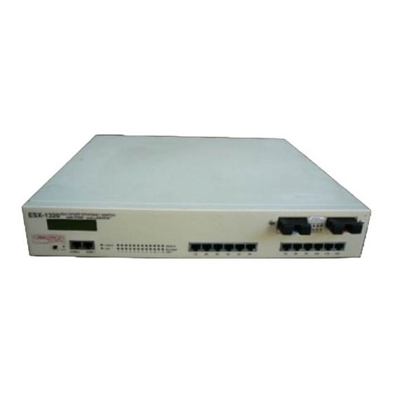
- Page 9 The ESX-1320 and ESX-1380 Ethernet Workgroup Switches, shown in Figure 1-1, are standalone network switch devices. Except for the difference in the network media supported (ESX-1320, RJ45 Twisted Pair ports and ESX-1380, Multimode Fiber Optic ST ports), the two ESX switches are identical in operation.
-
Page 10: Controls And Indicators
The ESX complies to the PLUS Architecture with Dual Intel i960 RISC processors and provides advanced management capabilities such as SNMP, RMON, and DLM. The ESX provides the option of using Cabletron Systems Distributed LAN Monitor (DLM) software to locally poll and monitor any SNMP or IP device. ESX-1320/ESX-1380 Installation Guide... - Page 11 Features Connectivity The ESX-1320 switch connects to the external Ethernet networks or workstations through the 12 standard RJ45 connectors on its front panel. The RJ45 connectors (interface ports) support Unshielded Twisted Pair (UTP) and Shielded Twisted Pair (STP) cabling at lengths up to 100 meters.
-
Page 12: Document Conventions
The ESX supports a wide variety of industry standard MIBs including RFC 1213 (MIB II), RFC 1757 (RMON), and RFC 1493 (Bridge MIB). A full suite of Cabletron Systems Enterprise MIBs provide a wide array of statistical information to enhance troubleshooting. -
Page 13: Related Manuals
RELATED MANUALS The following manuals may help the user to control and manage the ESX using SNMP network management systems. Cabletron Systems ESX-1320/ESX-1380 Local Management Guide Cabletron Systems SPECTRUM Element Manager Cabletron Systems SPECTRUM and SPECTRUM Portable Management Applications (SPMA) manuals... - Page 14 • Network load and frame size at the time of trouble (if known) • The serial and revision numbers of all Cabletron Systems products in the network • The device history (i.e., have you returned the device before, is this a recurring problem, etc.)
-
Page 15: Controls And Indicators
CONTROLS AND INDICATORS This chapter provides descriptions of the controls and indicators for the ESX-1320 and ESX-1380 Ethernet Workgroup Switches shown in Figure 2-1. ESX-1320 MULTI PORT ETHERNET SWITCH FDSE ™ LANVIEW ® WITH DISPLAY RESET COM 2 COM 1... -
Page 16: Lcd Display
• Cabletron Systems Local Management • Cabletron Systems SPECTRUM • Cabletron Systems SPECTRUM Element Manager for Windows • Cabletron Systems Remote SPECTRUM Portable Management Applications • Third Party SNMP compliant Network Management Packages Network management capabilities provide the necessary management tools for the ESX to operate at full capacity. - Page 17 To set a port for full duplex operation using MIB Navigator, proceed as follows: 1. Access Local Management as described in the ESX-1320/ESX-1380 Local Management Guide. 2. Select MIB Navigator via the Local Management Main Menu screen. MIBNav -> 3. Enter the following commands (shown in bold type) at the prompt as shown below: MIBNav ->...
- Page 18 Chapter 2: Controls and Indicators ESX-1320/ESX-1380 Installation Guide...
-
Page 19: Chapter 3 Installation
Pre-network installation testing (Section 3.8) • Connecting to a network (Section 3.9) Only qualified personnel should perform installation procedures. For information on how to install an optional BRIM, refer to your NOTE specific BRIM documentation. ESX-1320/ESX-1380 Installation Guide CHAPTER 3 INSTALLATION... -
Page 20: Unpacking The Esx
ESX-1320/ESX-1380 Installation Guide • ESX-1320/ESX-1380 Local Management Guide 3. If any of these items are missing, contact Cabletron Systems Technical Support immediately. For help, refer to Section 1.5. 4. Carefully remove the ESX from the shipping box. 5. Visually inspect the ESX. If there are any signs of damage, contact Cabletron Systems Technical Support immediately. -
Page 21: Removing The Chassis Cover
REMOVING THE CHASSIS COVER This section describes how to remove the ESX chassis cover. The chassis cover must be removed to install a BRIM, set the mode switch bank, or install SIMM memory upgrades. Do not remove the cover from the ESX when power is applied to the unit. - Page 22 RESET COM 2 COM 1 Figure 3-2 Removing the Mounting Brackets 19-Inch Rack RECEIVE TRANSMIT PORT 9 10 11 12 Screws (4) Rack Mounting Brackets (2) RECEIVE TRANSMIT PORT 9 10 11 12 Screws (4) ESX-1320/ESX-1380 Installation Guide 1574-05 1574-06...
-
Page 23: Setting Mode Switches
To reinstall the chassis cover, perform the removal procedures in reverse order. SETTING MODE SWITCHES Never adjust switch settings while the ESX has power applied to it. Not only is this dangerous, but the change in position activates the switch function only after reinstalling or cycling power to the ESX. - Page 24 Chapter 3: Installation ESX TOP VIEW WITHOUT COVER SDRAM FLASH BRIM NVRAM RESET Switch LDRAM ESX Front Panel Mode Switch Bank 15741-08 Figure 3-4 ESX Mode Switch Location/Component Layout ESX-1320/ESX-1380 Installation Guide...
- Page 25 Once the ESX is reset, the community names can either be reentered or the default settings (“public” or <Return>) may be used. Do not change the position of switch 8 unless it is necessary to NOTE reset the ESX community names to their factory default settings.
-
Page 26: Nvram Reset Switch
Otherwise, injury or damage to the ESX may occur. To change the NVRAM reset switch position, use a non-metallic tool to reach in through the chassis grillwork and move the switch. There is no need to remove the chassis cover to set the NVRAM reset switch. -
Page 27: Simm Upgrades
The ESX allows memory upgrades for Shared DRAM, Local DRAM, and FLASH EEPROM. This section explains how to locate and add/replace a Single In-line Memory Module (SIMM) for any of these memory types. Cabletron Systems currently offers an 8 MB upgrade for Local and Shared DRAM (Part Number 8MB-SCM-UGK-60). 3.5.1 Locating SIMMs Each memory type has a specific SIMM slot location on the ESX... - Page 28 4. Pivot the SIMM down until it locks into the clips in the SIMM slot, and the SIMM holes fit over the SIMM slot posts. SIMM Slot Connector Teeth SIMM Figure 3-6 Installing a FLASH SIMM 3-10 SIMM Slot Post SIMM Hole ESX-1320/ESX-1380 Installation Guide Clips 1574-10...
- Page 29 4. Pivot the SIMM back until it locks into the clips in the SIMM slot, and the SIMM holes fit over the SIMM slot posts. (See Figure 3-7.) SIMM Hole SIMM Slot Figure 3-7 Installing an SDRAM or LDRAM SIMM ESX-1320/ESX-1380 Installation Guide Connector Clip SIMM Upgrades SIMM Connector...
-
Page 30: Brim Connection
Section 3.7.2 describes the rackmount installation. To prevent possible personal injury and/or damage to the unit, do NOT connect power to the ESX until instructed to do so. 3-12 BRIM ESX Front Panel ESX-1320/ESX-1380 Installation Guide BRIM Connector 1574-28... -
Page 31: Tabletop Or Shelf Installation
In order to allow for proper cooling, there must be a two-inch clearance on either side and the back of the unit. CAUTION 18 IN. ESX-1320 6 IN. DISPLAY Figure 3-9 Tabletop or Shelf Installation ESX-1320/ESX-1380 Installation Guide 21 IN. MULTI PORT ETHERNET SWITCH FDSE ™ LANVIEW ® WITH RECEIVE TRANSMIT... -
Page 32: Rackmount Installation
Chapter 3: Installation 3.7.2 Rackmount Installation To install the ESX in a 19-inch rack, Cabletron Systems includes an accessory kit containing the rackmount brackets, mounting screws for attaching the rackmount brackets to the ESX chassis, and a strain-relief bracket for cable management. Screws to mount the ESX to the rack rails are provided by the user. - Page 33 MULTI PORT ETHERNET SWITCH ESX-1320 FDSE ™ LANVIEW ® WITH DISPLAY RESET COM 2 COM 1 Figure 3-11 Installing the Rack Mounting Brackets ESX-1320/ESX-1380 Installation Guide LANVIEW ® RECEIVE TRANSMIT 9 10 11 12 PORT COM 1 Screws (4) Rack Mounting Brackets (2)
-
Page 34: Connecting To The Power Source
ON (green) and the CPU LED turns ON (green) briefly. While booting, the ESX displays boot diagnostics and NOTE messages on Local Management, and the LCD also displays messages. 3-16 19-Inch Rack RECEIVE TRANSMIT 9 10 11 12 PORT Screws (4) ESX-1320/ESX-1380 Installation Guide 1574-05... -
Page 35: Pre-Network Installation Test
If the ESX does not boot successfully, all transmit LEDs flash amber for several seconds. If the CPU LED is not green, contact Cabletron Systems for assistance. Refer to Chapter 1, Getting Help. PRE-NETWORK INSTALLATION TEST Before connecting the ESX to a live network, you may want to test the ESX in a controlled situation to ensure that it is switching packets. - Page 36 (refer to individual workstation manuals for instructions on assigning server/client relationships). 5. Send packets between the two workstations to verify the proper operation of the ESX. If a failure occurs, contact Cabletron Systems Technical Support. Refer to Chapter 1, Getting Help. ESX-1320 MULTI PORT ETHERNET SWITCH FDSE ™...
-
Page 37: Connecting To The Network
The procedures for connecting segments to the ESX BRIM slot are detailed in the appropriate BRIM Installation Guide. To connect the ESX-1320 to the network, proceed to Section 3.9.1. To connect the ESX-1380 to a network, proceed to Section 3.9.2. - Page 38 Appendix B. If a link is not established, contact Cabletron Systems Technical Support. (Refer to Chapter 1, Getting Help). 3. Repeat step 2, above, until all connections to the ESX-1320 have been made. 3-20 ESX-1320/ESX-1380 Installation Guide...
-
Page 39: Connecting A 10Base-F Segment To The Esx-1380
The receive strand of the applicable port on the module connects to the transmit port of the fiber optic Ethernet device. Cabletron Systems recommends labeling fiber optic cables to indicate receive and transmit ends. Many cables are prelabeled, providing matching labels or tapes at both ends of each strand of cable. - Page 40 Appendix B. If you are still unable to establish a link, attempt to make the connection between the devices with another fiber optic cable. If this is unsuccessful, contact Cabletron Systems Technical Support. 3-22 ESX-1320/ESX-1380 Installation Guide 1098-13...
-
Page 41: Chapter 4 Troubleshooting
LCD and the RESET button. USING LANVIEW The ESX uses the Cabletron Systems built-in visual diagnostic and status monitoring system called LANVIEW. With LANVIEW, you can quickly scan the LANVIEW LEDs (Figure 4-1) of the ESX to observe network status or diagnose network problems. - Page 42 Blinking. Port in standby. Flashing to constantly on. Indicates collision rate. Solid. Port disabled. ESX-1320/ESX-1380 Installation Guide Error Condition Recommended Action Turn power on. Contact Cabletron Systems Technical Support. Contact Cabletron Systems Technical Support for assistance.
- Page 43 Table 4-1 LANVIEW LEDs (Continued) Color Receive Green Yellow ESX-1320/ESX-1380 Installation Guide Description Port enabled, no activity. Solid. Port enabled, link, no activity. Flashing. Indicates receive activity. Solid. No link, port disabled. Blinking. Link but port disabled. Using LANVIEW Error Condition Recommended Action No error.
-
Page 44: Troubleshooting Checklist
Refer to ESX Local Management Guide for proper console port pinouts. Refer to ESX Local Management Guide for Community Name Table setup. Refer to ESX Local Management Guide for IP address assignment procedure. Enable port. Check link to device. ESX-1320/ESX-1380 Installation Guide... - Page 45 RESET button parameters to reset to is pressed. factory default settings. NVRAM may be defective. ESX-1320/ESX-1380 Installation Guide Troubleshooting Checklist Recommended Action Discuss these configurations with Cabletron Systems Technical Support before implementing them into your network.
-
Page 46: Using The Reset Button
The RESET button shown in Figure 4-2 initializes the ESX processor without affecting the NVRAM. The RESET button may be used in conjunction with the NOTE NVRAM reset switch (not shown) to also initialize the NVRAM as described in Section 3.4. MULTI PORT ETHERNET SWITCH ESX-1320 FDSE ™... -
Page 47: Using The Lcd
System Messages • Failure or Error Messages * *These messages are displayed as an associated event occurs and are not saved to be displayed later using the DISPLAY button. ESX-1320/ESX-1380 Installation Guide FDSE ™ LANVIEW ® COM 1 Using the LCD... -
Page 48: Unsaved Initialization Messages
TFTP Req. State Cabletron TFTP Complete Cabletron Programming Flash Cabletron Boot Complete Cabletron Decompress Image Cabletron Boot From Flash Cabletron RARP Req. State Cabletron TFTP in Progress Cabletron Erasing Flash Cabletron Flash Programmed Cabletron Test in Progress ESX-1320/ESX-1380 Installation Guide... -
Page 49: Static System Messages
DISPLAY button. To Display the Messages With the product name (e.g., CABLETRON ESX-1320) displayed, momentarily press the DISPLAY button to step to the first message. Each time you press the DISPLAY button, the next message is displayed until the last message. - Page 50 Displays Auto for the Baud Rate for COM 1 Port. Displays the current function of the COM 1 Port. Displays Auto for the Baud Rate for COM 2 port. Displays the current function of the COM 2 Port. ESX-1320/ESX-1380 Installation Guide...
-
Page 51: Alarm Messages
From the product name display Press and hold the DISPLAY button for 3 seconds while the product name (e.g., CABLETRON ESX-1320) is displayed. When the button is released, the display steps to the first of the saved Alarm Messages described in Table 4-4. Thereafter, each time you press the DISPLAY button, the next message is displayed. -
Page 52: Saved System Messages
Displays the individual link status of ports 1 through 13. Displays the individual link status of ports 1 through 13. Indicates if a Switch port is in stand-by. Individually for ports 1 through 13. Indicates if a Switch port is on-line. Individually for ports 1 through 13. - Page 53 From the product name display Press and hold the DISPLAY button for 3 seconds while the product name (e.g., CABLETRON ESX-1320) is displayed. When the button is released, the display steps to the Alarm Messages. Then press and hold the DISPLAY button for another 3 seconds. When the button is released, the display steps to the first of the saved System Messages.
-
Page 54: Failure Or Error Messages
The failure or error messages are as follows: Cabletron Ctrl. Reg. Err. Cabletron SDRAM Failure Cabletron SONIC Failure Cabletron Console SCC Error Cabletron 82C54 Failure 4-14 Cabletron BBRAM Failure Cabletron Modem SCC Failure Cabletron Bit Swap Failure Cabletron LDRAM Failure ESX-1320/ESX-1380 Installation Guide... -
Page 55: A.1 Functionality
This appendix provides the operating specifications for the Cabletron Systems ESX. Cabletron Systems reserves the right to change these specifications at any time without notice. FUNCTIONALITY FLASH Memory: Shared Sonic Memory: Internal Processor: NVRAM: Ethernet Controller: CPU Memory: COM PORT 1 AND COM PORT 2... -
Page 56: A.3 Environmental Requirements
FCC Part 15, VCCI Class 1, EN 55022, EN 50082-1, and 89/336/EEC 7.11H x 43.18W x 34.29D (cm) 2.8H x 17W x 13.5D (in) 3.18 kg (7 lb) 100-125 V~ / 4.0 A 200-250 V~ / 2.0 A Single-phase 50/60 Hz ESX-1320/ESX-1380 Installation Guide... -
Page 57: B.1 Network Requirements
Refer to the sections which follow that apply to your specific network configuration. 10BASE-T TWISTED PAIR NETWORK When connecting a 10BASE-T segment to the ESX-1320, ensure the network meets the following requirements: • Length: The IEEE 802.3 10BASE-T standard requires that 10BASE-T devices transmit over a 100 meter (328 foot) link using 22-24 AWG unshielded twisted pair wire. - Page 58 • Impedance: Cabletron Systems 10BASE-T products work on twisted pair cable with 75 to 165 ohms impedance. Unshielded twisted pair cables typically have an impedance of between 85 and 110 ohms. You can also use Shielded Twisted Pair cables, such as IBM Type 1 cable, but keep in mind that this cable has an impedance of 150 ohms.
-
Page 59: Multimode Fiber Optic Network
• Length: The maximum possible multimode fiber optic cable length is 2 km (1.24 miles). However, IEEE 802.3 FOIRL specifications specify a maximum of 1 km (0.62 miles). ESX-1320/ESX-1380 Installation Guide Multimode Fiber Optic Network... - Page 60 Appendix B: Ethernet Cabling Requirements ESX-1320/ESX-1380 Installation Guide...
-
Page 61: Index
COM ports pin assignments of A-1 Connectivity ESX-1320 1-3 ESX-1380 1-3 Controls and indicators location of 2-1 Crosstalk B-2 ESX-1320/ESX-1380 Installation Guide INDEX Electrical specifications A-2 Electromagnetic Compatibility A-2 Environmental requirements A-2 functionality A-1 installation of 3-12 management 1-4 memory 1-3... - Page 62 Processor. See i960 RISC processor Propagation delay B-2, B-3 Rackmount installation of 3-14 Regulatory electromagnetic compatibility A-2 safety A-2 RESET button using the 4-6 Safety A-2 SDRAM SIMM installation of 3-11 Setting port operation for simplex or duplex 2-3 ESX-1320/ESX-1380 Installation Guide...
- Page 63 Specifications A-1 Switching, types supported 1-4 Tabletop or shelf installation 3-13 Troubleshooting using LANVIEW LEDs for 4-1 using LCD messages for 4-7 using the checklist for 4-4 Twisted pair connection of 3-19 Unpacking the ESX 3-2 ESX-1320/ESX-1380 Installation Guide Index Index-3...
- Page 64 Index Index-4 ESX-1320/ESX-1380 Installation Guide...
-
Page 65: Power Supply Cord
The mains cord used with this equipment must be a 2 conductor plus ground type with minimum 0.75 mm square conductors and must incorporate a standard IEC appliance coupler on one end and a mains plug on the other end which is suitable for the use and application of the product and that is approved for use in the country of application.
Need help?
Do you have a question about the ESX-1320 and is the answer not in the manual?
Questions and answers