
Related Manuals for Landoll BRILLION SL Series


Summary of Contents for Landoll BRILLION SL Series
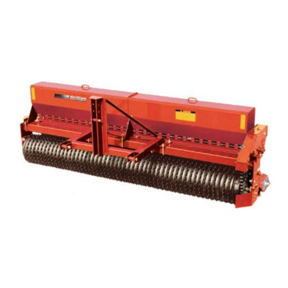
- Page 1 Turfmaker Seeder Models SL and SLP 8, 10’, and 12’ Operator’s Manual LANDOLL CORPORATION 1900 North Street Marysville, Kansas 66508 (785) 562-5381 800-428-5655 ~ WWW.LANDOLL.COM 807rev1215 1P342...
-
Page 3: Table Of Contents
Table of Contents Safety Information Introduction ..............1-1 Description of Unit . - Page 4 Operation Operation of Seeder ............3-1 Seed Rate Adjustment .
-
Page 5: Safety Information
Brillion Farm Equipment, by Landoll, shall have no or its components and inferior operation. warranty obligation unless each product is registered, within 10 days of retail purchase, using the Landoll Corporation Ag Products on-line registration process. IMPORTANT Please refer to the Ag Products Policy and Procedures... -
Page 6: Understanding Safety Statements
SAFETY INFORMATION Federal law requires that you explain the safety and Order replacement decals through your Brillion dealer. operating instructions furnished with this machine to all Keep these signs clean so they can be observed readily. operators before they are allowed to operate the It is important to keep these decals cleaned more machine. -
Page 7: Attaching, Detaching And Storage
SAFETY INFORMATION Keep clear of overhead power lines and other NOTE obstructions when transporting. Know transport height and width of your machine. Refer to transport dimensions On most tractors relieving hydraulic pressure can be page 5-1. accomplished by operating valves after the engine is stopped. - Page 8 SAFETY INFORMATION Use a safety chain to help control drawn machinery A second chain should be used between each should it separate from the tractor drawbar. implement. Use a chain with a strength rating equal to or greater than Attach the chain to the tractor drawbar support or the gross weight of towed machinery, which is 10,100 specified anchor location.
-
Page 9: Decals
SAFETY INFORMATION Decals Figure 1-3: 8 Ft Model Decals... - Page 10 SAFETY INFORMATION Figure 1-4: 10 Ft Model Decals 1P342...
- Page 11 SAFETY INFORMATION Figure 1-5: 12 Ft Model Decals...
- Page 12 SAFETY INFORMATION Figure 1-6: Hitch Decals 1P342...
- Page 13 SAFETY INFORMATION Figure 1-7: Decals...
- Page 14 SAFETY INFORMATION Table provided for general use. NOTES: 1-10 1P342...
-
Page 15: Assembly Instructions
Chapter 2 Assembly Instructions • Park the seeder in a work area that has a level CAUTION surface and make sure it is blocked securely so that it cannot roll. Do Not Work On Or Under This Machine Unless Securely Blocked And Supported By A Hoist Or NOTE Tractor Or By Other Sufficient Means! - Page 16 ASSEMBLY INSTRUCTIONS 3. Remove 5/8” shipping bolt from right side of frame CAUTION which locks rear roller down. Bolt is located in a position similar to the parking pin. Do not disengage pin unless seeder is fully 4. Install the LED Warning Lamps and Harnesses. See attached to a tractor.
-
Page 17: Pull Type Seeder Assembly
ASSEMBLY INSTRUCTIONS Pull Type Seeder Assembly • Park the seeder in a work area that has a level surface and make sure it is blocked securely so that it cannot roll. Drawbar Assembly NOTE When shipped, seeder comes assembled except for lights, wheels, and drawbar. - Page 18 ASSEMBLY INSTRUCTIONS 4. After the drawbar is attached route the hoses along drawbar toward the tractor. Use the hose clamps provided to anchor the hoses to the drawbar. See Figure 2-4. Figure 2-4: Drawbar Hydraulic Hoses 5. Install hub and spindles into the wheel arms and Charge the Hydraulic System.
- Page 19 ASSEMBLY INSTRUCTIONS Figure 2-5: Spindle 7. Remove the (2) 5/8” shipping bolts which lock the rear roller arms down. One bolt is used on each side of the machine. See Figure 2-6. Figure 2-6: Shipping Bolt 8. Install the LED Warning Lamps and Harnesses. See ...
-
Page 20: Led Warning Lights
ASSEMBLY INSTRUCTIONS LED Warning Lights Figure 2-7: LED Warning Lights 1P342... - Page 21 ASSEMBLY INSTRUCTIONS Table provided for general use. NOTES:...
- Page 22 ASSEMBLY INSTRUCTIONS Figure 2-8: LED Warning Lights, 12’ Drawbar Assembly 1P342...
- Page 23 ASSEMBLY INSTRUCTIONS NOTE NOTE 12 foot drawbar model is shown, 8 and 10 foot models The plug on the other end of the 7 Pin harness connects similar. to the tractor socket when in use. When not in use, it can be stored in the Plug Holder on the hose support bracket.
- Page 24 ASSEMBLY INSTRUCTIONS Figure 2-10: LED Warning Lights, 8’ 3 Pt. Assembly 2-10 1P342...
- Page 25 ASSEMBLY INSTRUCTIONS 11. Attach the SMV sign to the SMV Mount located on NOTE the center on the Front Frame using (2) 5/16-18 x 1 Screws, Flat Washers, and Locknuts. 8 foot pick-up model is shown, 10 and 12 foot models similar.
-
Page 26: Seed Shaft Sensor Kit (Optional)
ASSEMBLY INSTRUCTIONS Seed Shaft Sensor Kit (Optional) Identify the seed cups on either side of the Magnet Wheel Assembly and remove the 1/4-20 hardware. Insert Remove the two #10 x 24 x 3/4” self tapping screws from Sensor into Shaft Sensor Bracket slot. the Magnet Wheel Assembly. - Page 27 ASSEMBLY INSTRUCTIONS Figure 2-13: Seed Shaft Sensor Mounting Dimension - Seedmeter 2-13...
-
Page 28: Seed Shaft Sensor Schematic
ASSEMBLY INSTRUCTIONS Seed Shaft Sensor Schematic 5. On left side seal the plug that says Electric Clutch using a 2-Pin Shroud and Cavity Plug to protect it Mount Console with Clutch Control on Tractor. from the environment. See Figure 2-14. 1. -
Page 29: Agitator Kit (Optional)
ASSEMBLY INSTRUCTIONS Agitator Kit (Optional) 9. Tighten locking collars in direction of rotation (counter-clockwise when viewed from the right end of machine). 1. Remove knock-outs for 3/4” flangette bearings. 10. Rotate agitator assembly to be sure it turns freely. These are located at each end and center of seed 11. - Page 30 ASSEMBLY INSTRUCTIONS Figure 2-17: 8 Ft Agitator 2-16 1P342...
- Page 31 ASSEMBLY INSTRUCTIONS Figure 2-18: 10 Ft Agitator 2-17...
- Page 32 ASSEMBLY INSTRUCTIONS Figure 2-19: 12 Ft Agitator 2-18 1P342...
-
Page 33: Electronic Acre Meter Kit (Optional)
ASSEMBLY INSTRUCTIONS Electronic Acre Meter Kit (Optional) NOTE The acre meter consists of three main parts, the acre meter, the pick-up and the magnet wheel. 1. Use the acre meter bracket as a guide and drill two 13/32” holes into seedbox at location shown in illustration. - Page 34 ASSEMBLY INSTRUCTIONS Figure 2-22: Electronic Acre Meter (3 of 3) 4. Adjust the pickup switch and bracket so the centerline of magnet wheel and pick up switch are horizontally and vertically aligned with maximum 1/8” between magnet wheel and pick up switch. Firmly tighten all screws.
-
Page 35: Scraper Kit (Optional)
ASSEMBLY INSTRUCTIONS Scraper Kit (Optional) remover. Do not fasten securely at this time. 2. Attach vertical brackets loosely and assemble (Cannot be used with Coil Tine Track Remover Kit) scraper angle to them. Attach two center scrapers at See Figure 2-23. center hole locations and then attach all of the regular scrapers. -
Page 36: S-Tine Tire Track Remover (Optional)
ASSEMBLY INSTRUCTIONS S-Tine Tire Track Remover installed. This kit must be used with standard 9J442 long three point hitch on pickup machines. The Wheel (Optional) Track Remover is furnished with 6 S-tines. More or less tines may be used as required. 1. -
Page 37: Coil Tine Track Remover (Optional)
ASSEMBLY INSTRUCTIONS Coil Tine Track Remover 5. Attach the adjusting angles to frame brackets with lockscrews. Secure the adjusting angle from (Optional) swinging with a 1/2” clevis pin and hair pin cotter. 6. Fasten the bar and tine assemblies to the adjusting NOTE angles with 1/2”... -
Page 38: Speed Up Kit (Optional)
ASSEMBLY INSTRUCTIONS Speed Up Kit (Optional) 4. Remove locking collar from left side of the front transmission shaft. Seed rates can be doubled by using a 26-tooth sprocket. 5. Remove bearing bolts from right side of the front Procedure is as follows: See Figure 2-26. transmission shaft. -
Page 39: Turfmaker Sprockets (Optional)
ASSEMBLY INSTRUCTIONS Turfmaker Sprockets (Optional) Turfmaker Sprockets provide extra traction in certain soil types. See your Landoll/Brillion Dealer for more information. 1. Position the Turfmaker Wheel Spacer between each 4C689 Sand Wheel. See Figure 2-27. 2. At the end of the process slide a Half Wheel onto the axle next to the last Wheel Spacer. - Page 40 ASSEMBLY INSTRUCTIONS Table provided for general use. NOTES: 2-26 1P342...
-
Page 41: Operation
Operation Operation of Seeder This chapter will cover the basic operation and procedures for the Landoll Brillion Alfalfa Seeder. Be sure to read and understand the Safety Procedures and Cautions starting on page 1-2. Seeder Transport Lock (Pull Type Only) For field operation: Disengage each transport lock and replace the pin. - Page 42 OPERATION Figure 3-3: Hitch Adjustment Parking Pin (Pick Up Only) CAUTION To prevent machine from tipping backward on frame, disengage parking pin only when the seeder is fully attached to the tractor. Be sure to observe the following sequence: When hooking up the seeder: 1.
-
Page 43: Seed Rate Adjustment
OPERATION Seed Rate Adjustment NOTE Wrenches used for adjustment are stored on a pin at the back of the transmission. WARNING • To Prevent damage to seed meters, do not apply excessive force to adjusting nuts. This is especially important when closing meters as seed in flutes can be pinched between cut-off and washer in seed cup. - Page 44 OPERATION Figure 3-7: Seed Rate Adjustment 1P342...
-
Page 45: Seed Rate Calibration
OPERATION Seed Rate Calibration 4. Turn the 15/16” hex on the transmission clockwise as follows: Machine may be calibrated for unlisted seed as follows: • 136 revolutions for 8 foot seeder. 1. Remove the drive bolt from the 6 tooth #A550 chain •... - Page 46 OPERATION Figure 3-9: Seed Rate Chart 1P342...
-
Page 47: Electronic Acre Meter Kit - Optional
OPERATION Electronic Acre Meter Kit - 1. If you know the number, select it using the UP and DOWN buttons. When you press the /FUNC Optional button, the Acre Counter will accept the number in the display as the new pulses per 400 feet. See IMPORTANT Table 3-1. -
Page 48: Quick-Start Settings For Loup Acre Meters Prior To 05/15/2012
OPERATION If the password is not correct, you will not be able to 5. Enter the width of seeder using the up or down change the acre counter settings. When the “PASS” buttons for the model listed in the chart. See function is selected again, “Ent”... - Page 49 OPERATION Table 3-1: Acre Meter Settings (After 05/15/2012) MODEL PULSES WIDTH SSP T604 SSP4 SSP5 SSP6 SSP8 SSP10 SS10 10.0 SSP12 SS12 12.0 SSP108 SS108 SSP110 SS110 10.0 SSP112 SS112 12.0 SSP208 SSP2081 SS208 SS2081 SSP210 SSP2101 SS210 SS2101 10.0 SSP212 SSP2121 SS212...
- Page 50 OPERATION Table 3-2: Acre Meter Settings (Prior to 05/15/2012) MODEL Pulses Width SSP T604 SSP4 SSP5 SSP6 SSP8 SSP10 SS10 SSP12 SS12 SSP108 SS108 SSP110 SS110 SSP112 SS112 SSP208 SSP2081 SS208 SS2081 SSP210 SSP2101 SS210 SS2101 SSP212 SSP2121 SS212 SS2121 SSP308 SS308 SSP310...
-
Page 51: Maintenance & Adjustment
Chapter 4 Maintenance & Adjustment General Torque Specifications (rev. 4/97) This chart provides tightening torques for general purpose applications when special torques are not specified on process or drawing. Assembly torques apply to plated nuts and capscrews assembled without supplemental lubrication (as received condition). They do not apply if special graphite moly-disulfide or other extreme pressure lubricants are used. -
Page 52: Hydraulic Fitting Torque Specifications
MAINTENANCE & ADJUSTMENT Hydraulic Fitting Torque Specifications 37 degree JIC, ORS, &ORB (REV. 10/97 This chart provides tightening torques for general purpose applications when special torques are not specified on process or drawing. Assembly torques apply to plated nuts and capscrews assembled without supplemental lubrication (as received condition). They do not apply if special graphite moly-disulfide or other extreme pressure lubricants are used. -
Page 53: Tires
MAINTENANCE & ADJUSTMENT Tires Recommended inflation pressure is a follows: 7.00/7.60-15 6 ply rating..40 psi 9.5 L-15 6 ply rating..32 psi 11 L-15 8 ply rating..28 psi Lubrication • All machines have a grease zerk on the bearing on each end of the front and rear rollers. Pull type machines have a zerk on each wheel arm pivot as well. -
Page 54: Feed Cup Adjustment
MAINTENANCE & ADJUSTMENT Figure 4-4: Chain Tightening Feed Cup Adjustment 3. Individual cups can be adjusted by loosening their mounting bolts, moving cups and then re-tightening. All cups must be set the same to ensure seed uniformly. To check, set the adjusting nut to 0-A. The “A” on the adjustment nut is positioned over the “0”... - Page 55 MAINTENANCE & ADJUSTMENT Figure 4-5: Feed Cup Adjustment...
-
Page 56: Roller Wheels
MAINTENANCE & ADJUSTMENT Roller Wheels Occasionally it is necessary to loosen clamp bands and tighten roller wheel assemblies. As nearly as possible, peaks on rear wheels should line up with valleys on the front wheels. This requires adjusting both end clamps on the rear axle drum. -
Page 57: Hydraulics
MAINTENANCE & ADJUSTMENT Hydraulics Figure 4-7: Hydraulic Schematic... -
Page 58: Acre Meter Troubleshooting
MAINTENANCE & ADJUSTMENT Acre Meter Troubleshooting 4. If step 3 works then wave a magnet in front of the Pick-up Switch face with it re-connected to the display and see if the display increments up. If not, IMPORTANT put an ohm meter or continuity tester on the contacts Acre Meter is dust and splash resistant, under no of the Pick-up Switch harness and place a magnet in circumstances should this unit be submerged in any... -
Page 59: General Reference Tables And Specifications
Chapter 5 General Reference Tables and Specifications Figure 5-1:... - Page 60 GENERAL REFERENCE TABLES AND SPECIFICATIONS Figure 5-2: 1P342...
- Page 61 Document Control Revision Log: Date Revision Improvement(s) Description and Comments 07/2008 Initial Release 09/2013 807rev0913 Added LED Warning Lights, Updated Drawings 12/15 807rev1215 Decal Locations, Updated Drawings...
- Page 62 Equipment from Landoll Corporation is built to exacting standards ensured by ISO 9001 registration at all Landoll manufacturing facilities. Turfmaker Seeder Models SL and SLP 8’, 10’, and 12’ Operator’s Manual Re-Order Part Number 1P342rev1215 LANDOLL CORPORATION 1900 North Street...
Need help?
Do you have a question about the BRILLION SL Series and is the answer not in the manual?
Questions and answers