Table of Contents
Advertisement
Quick Links
Advertisement
Table of Contents

Related Manuals for Formax Atlas C350


Summary of Contents for Formax Atlas C350
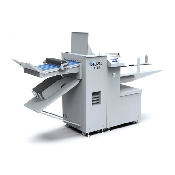
- Page 1 Atlas C350 Automatic Air-Feed Programmable Folder/Creaser OPERATOR MANUAL 10/2021...
- Page 2 WARNING: This is a Class A product. In a domestic environment this product may cause radio interference in which case the user may be required to take adequate measures. The product (System) which is connected to this machine will be class A. NOTE: The domestic environment is an environment where the use of broadcast radio and television receivers may be expected within a distance of 10m of the apparatus concerned.
- Page 3 Introduction This manual contains instructions on the operation and maintenance of this machine. To get maximum versatility from this machine all operators should carefully read and follow the instructions in this manual. Keep this manual in a handy place near the machine. Please read the Safety Information before using this machine.
- Page 4 Safety Information When using this machine, following safety precautions should always be followed. Safety During Operation WARNING: • To avoid hazardous situations like for instance electric shock or danger while exposed to moving, rotating or cutting devices, do not remove any covers, guards or screws other than those specified in this manual.
- Page 5 CAUTION: • The machine and its peripherals must be installed and maintained by a customer service representative who has completed the training course on those models. • Always follow all warnings marked on, or supplied with, the equipment. • When you disconnect the power plug from the wall outlet, always pull the plug (not the cable). •...
- Page 6 Page intentionally blank.
-
Page 7: Table Of Contents
TABLE OF CONTENTS What You Can Do With This Machine ..........9 Guide To Components ..................... 10 Atlas C350 ..........................10 Feeder Module ..........................11 Folding Module .......................... 12 User Interface ..........................13 1. Basics ....................17 Paper..........................17 Paper Guidelines ........................17 Creasing .......................... - Page 8 Paper Size ..........................59 Pre-set Patterns .......................... 61 Custom Job ..........................63 Roller Gap Adjustment ........................ 64 Atlas C350 Quick Reference Sheet ..................... 65 Saving and Loading Jobs ......................66 Counters ............................. 67 The Tools Screen ......................68 Overview ............................. 68 Feeder Settings ..........................
-
Page 9: What You Can Do With This Machine
The Atlas C350 has the capability to handle the new long formats that the print engines now can produce. It can also be equipped with dual creasing blades allowing up and down creasing in a single pass. -
Page 10: Guide To Components
Guide To Components Atlas C350 9. Crease only delivery 1. Outfeed conveyor 10. Storage shelves 2. Crease skew adjustment 11. User interface (UI) 3. Top cover 12. Feeder skew adjustment wheel 4. Registration area 13. Magnetic paper guides 5. Vacuum belts (underneath) 14. -
Page 11: Feeder Module
Feeder Module NOTE: Covers removed for clarity. 9. Maximum paper stack height for sheets 1. User interface (UI) longer than 700 mm (27.6”) 2. USB port for software updates 10. Paper stack height sensor Q4 3. Front separation fan 11. Separated paper (SP) sensor Q12 4. -
Page 12: Folding Module
Folding Module 1. Crease skew adjustment 2. Rotary tool carrier 3. Dynamic Crease unit 4. Dynamic Crease pressure lock 5. Dynamic Crease pressure adjustment 6. Paper path – can be replaced with an optional static creaser 7. Input rollers 8. Input sensor... -
Page 13: User Interface
User Interface The Atlas C350 has a User Interface (UI) which allows for setting up jobs and viewing / modifying machine settings and properties. Detailed descriptions of each menu and sub-menu are found in Section 2 of this Operator Manual. - Page 14 Tools and Accessories The following tools and accessories are included with the Atlas C350 Part number Description 601-167 Digital thickness gauge 1-99-12 28T rotary perforation blade (7 TPI) 1-99-35 Rotary perforation / slitting anvil 142-115551 Multi-purpose wrench 601-185 Sensor cleaning brush...
- Page 15 AF-30 Heavy Scoring Wheel The Atlas C350 is supplied with a single Dynamic Creasing unit. A static creaser can be fitted to this machine. This enables up/down creasing in a single pass and (with the cross- perforation kit) creasing and cross-perforation in a single pass.
- Page 16 Page intentionally blank.
-
Page 17: Basics
1. Basics Paper Paper Guidelines Paper comes in many different makes, types and finishes. There are many ways to print on the paper and then protect that printed image. The grain direction, fiber structure, sub- strate thickness, porosity, coating type, bond strength of the coating, water content, relative humidity and many other things can affect how the paper will behave when you crease and fold it. -
Page 18: Creasing
Creasing About the Crease A crease stops the paper and printed image of a document from cracking when it is folded. The crease is made when a sheet of paper is compressed between the two parts of a mechanism known as a blade set. The blade set uses an ANVIL and a BLADE to form the crease. -
Page 19: Choose The Correct Creasing Blade Set
Choose the Correct Dynamic Crease Blade Set This machine is supplied with a single standard crease blade set. Several optional blade sets are available. Refer to the table below to see which type of blade set is most suitable for your job. Sheet Thickness Blade Set Crease Width... -
Page 20: Replacing Creasing Blade Set
Replacing the Dynamic Crease Blade Set This machine is supplied with a single Standard crease blade set. The blade set can be rotated to produce up or down facing creases without flipping the stack of paper. NOTE: Optional blade sets to produce narrower crease are available. To flip the crease blade set or replace it with another set: 1. - Page 21 4. Loosen the locking knobs (in red) in the direction indicated by the arrows [A]. 5. Slide the Locking knobs (in red) to the centre [B] to release locking pins. 6. Pull the blade set upwards to remove it [C]. Continued on next page...
- Page 22 7. Push Blade Guide Block [D] to the side and remove Blade Link [E]. 8. Attach Blade Links and Bridge to new blade set and reinsert. NOTE: A label on the blade set indicates paper movement direction. Ensure the blade set is in- stalled in the correct direction.
- Page 23 9. Close the top cover. 10. From the touchscreen interface choose Tools -> Change Crease Blades. 11. Use this menu to choose the blade set that has just been installed and set its direction (crease up or crease down). Click the green check mark to confirm.
-
Page 24: Adjusting Crease Depth
Adjusting Crease Depth DynaCrease 1. Run a proof sheet and inspect the output. Jobs Counter Home Media Tools Fold Crease ABC 123* Pattern SRA3 0.15mm, 200gsm Media Letter fold AUTO Feeder Counter: 2300 Clear Batch: 23/50 Clear 2. If the crease is too shallow or too deep loosen the locking knobs. 3. -
Page 25: Choose The Correct Blade Set (Optional)
Choose the Correct Quick Release Blade Set (optional) This machine is supplied with a single standard crease blade set. Several optional blade sets are available. Refer to the table below to see which type of blade set is most suitable for your job. -
Page 26: Replacing Blade Sets (Optional)
Replacing Quick Release Blade Sets (optional) This upgrade kit is supplied with a single Standard crease blade set. The blade set can be rotated to produce up or down facing creases without flipping the stack of paper. NOTE: Optional blade sets to produce narrower creases or to cross perforate are available (see the “Choose the Correct Quick Release Blade Set”... - Page 27 4. Lift the Bridge Assembly up and remove it. 5. Pull the blade set upwards to remove it. 6. Insert the new blade set. NOTE: A label on the blade set indicates paper movement direction. Ensure the blade set is in- stalled in the correct direction.
- Page 28 9. From the touchscreen interface choose Tools -> Change Crease Blades. 10. Use this menu to choose the blade set that has just been installed and set its direction (crease up or crease down). Click the green check mark to con irm.
-
Page 29: Adjusting Crease Blade Depth (Optional)
Adjusting Crease Depth Quick Release Blade (optional) 1. Run a proof sheet and inspect the output. Counter Media Jobs Tools Home Fold Crease ABC 123* Pattern SRA3 0.15mm, 200gsm Media Letter fold AUTO Feeder Counter: 2300 Clear Batch: 23/50 Clear 2. -
Page 30: Setting Crease Tilt Knob
Setting Crease Tilt Knob 1. Run a proof sheet with a single crease and inspect the output. 2. If the crease is skewed, adjustment is necessary. NOTE: Wrong crease positions are marked in red, correct crease position is marked in green. Crease Feed direction 3. - Page 31 4. Move the knob slightly, either to the left or to the right depending on the direction of the crease skew. 5. Rotate the knob clockwise to secure it. 6. Run another proof sheet to check if the crease is now perpendicular to sheet edge. Repeat steps 2 to 5 if necessary.
-
Page 32: Perforation
A perforation is a series of cuts in the paper that allows it to be easily and neatly separated into two or more pieces. Perforation can be used to create coupons, tickets, return slips and other products. The Atlas C350 can perforate sheets in two perpendicular directions: • In the process direction using rotary tools •... -
Page 33: Rotary Perforation
Rotary Perforation Rotary Perforation The rotary perforation process uses circular blades mounted on the rotary tool carrier to perforate sheets in the process direction. NOTE: 1. Perforation and creasing can be carried out simultaneously. However, if any skew adjustment is made to the feeder in order to compensate for the perforation line being “out of square”, this may affect the accuracy of the crease. - Page 34 A - Top shaft D - Bottom shaft B - Drive wheel E - Drive hub C - Perforation blade F - Anvil NOTE: Up to 5 rotary blades can be mounted on the rotary tool carrier. 3. Using a 2 mm hex key loosen one of the drive wheels [B] and slide it away from any obstructing drive wheels or hubs in order to mount the blade.
- Page 35 6. Mount a matching pair of anvils [F] and secure them to the drive wheel using a 2.5 mm hex key 7. Position the perforation blade [C] using the ruler on the rotary tool carrier. Secure the drive wheel in place using a 2 mm hex key. 8.
- Page 36 13. Loosen locking knob G by rotating it counterclockwise. 14. Use the adjustment wheel H to set paper registration wall angle. If the sheet skews away from the operator (L1 > L2) turn the wheel down. If the sheet skews towards the op- erator (L1 <...
- Page 37 Page intentionally blank.
-
Page 38: Cross Perforation
Cross Perforation Blade removal / replacement WARNING! All blades are very sharp: use extreme caution. Leather gloves must be worn whenever handling the blades. 1. Locate the Allen tools supplied with the Cross Perforation kit. 2. Place the cross perforation tool on a table in the orientation shown below. 3. - Page 39 WARNING! All blades are very sharp: use extreme caution. Leather gloves must be worn whenever handling the blades. 5. Loosen grub screws [A] (x13). Shown on previous page. 6. Lift out the Blade [E]. 7. Replace with required blade. Double stacking is NOT supported. Continued on next page...
- Page 40 WARNING! All blades are very sharp: use extreme caution. Leather gloves must be worn whenever handling the blades. 8. Insert the blade into the blade channel. 9. Ensure the blade is fully inserted and does not exceed the notch [B]. Shown on previ- ous page.
-
Page 41: Anvil Strip Removal / Replacement
Anvil strip removal / replacement WARNING! All blades are very sharp: use extreme caution. Leather gloves must be worn whenever handling the blades. NOTE: Before replacing anvil strip decrease perforation depth to avoid causing excess strain on motor and reducing lifespan of anvil strip. adjustment procedure can be found under 'perforation depth adjustment'. - Page 42 WARNING! All blades are very sharp: use extreme caution. Leather gloves must be worn whenever handling the blades. 4. Rotate the bottom assembly 180° from the top assembly as shown below. 5. Loosen grub screws [A] (x5). Shown on previous page. 6.
-
Page 43: Perforation Depth Adjustment Procedure
Perforation depth adjustment procedure WARNING! All blades are very sharp: use extreme caution. Leather gloves must be worn whenever handling the blades. NOTE: Before adjusting depth of perforation ensure the anvil strip does not require replacement. 1. Locate the tools supplied with the Cross Perforation kit. 2. -
Page 44: Folding
Roller Gap 1 Fixed Roller Roller Gap 3 1st Fold Knife (K1) This machine has many different fold configurations available. The fold configurations are shown in detail in the “Atlas C350 Quick Reference Sheet” in Section 2 of this manual. -
Page 45: Deflects
Deflects About Deflects The Flying Knife folding system has a unique function that lets the machine pass flat sheets through the fold rollers. This operation is known as a deflect. When you choose to do a half fold on K1 or K2, the fold knife that is not used to fold the document becomes a deflector. - Page 46 Page intentionally blank.
-
Page 47: Setting Up A Job
2. Setting Up a Job Getting Started Turning the Machine On/Off 1. Ensure the main power cord is plugged into the machine [A] and the wall socket. 2. Ensure the CAN termination plug [B] is plugged in. 3. Toggle the main power switch [C] to turn the machine on. 4. -
Page 48: Job Preparation
Job Preparation Paper stack preparation Before loading paper in this machine, it is recommended to fan the sheets as shown. 1. Hold the paper stack on a flat surface as shown 2. Bend the paper stack 3. Use your fingers and thumbs to pinch the paper stack 4. - Page 49 Paper stack preparation (continued) 5. Flex the paper back and forth a couple of times to break surface tension and preseparate the sheets 6. Realign the sheets into a stack before putting them into the tray NOTE: If the sheets you are using are too stiff or too large format to carry out the above proce- dure, fan the front edge of the sheets when loading them in the machine.
-
Page 50: Measuring The Paper Curl
Measuring the paper curl Take a sample of the stack (about 15 mm / 0.59” high) and place it on a flat surface 1. Take the midpoint as reference and do all the measurements within the marked area of the picture (from the center to the leading edge in paper feed direction) 2. -
Page 51: Loading Paper
Loading Paper 1. Take a stack of printed paper and place it on the feeder table in the desired orientation. NOTE: If using sheets longer than 450 mm (17.7”), but shorter than 700 mm (27.6”) extend the built-in pull-out table. If using sheets longer than 700 mm (27.6”) see the optional “Feeder Table Extension”... -
Page 52: Feeder Table Extension (Optional)
Feeder Table Extension (optional) Install table extension if using sheets longer than 700 mm (27.6”): 1. Ensure the built-in pull-out table [A] is fully stowed. 2. Hook the table extension [B] into the lift [C] as shown. NOTE: The feeder table extension has a built-in pull out part that can be used to feed sheets up to 1300 mm (51”). -
Page 53: Stacker Settings
Stacker Settings Stacker Settings Menu The machine automaticaly adjusts the stacker settings when a job is selected, these set- tings will not always be appropriate for certain custom jobs or all paper types see 'Paper Guidlines' section. If the job being run is not stacking correctly follow the below section. 1. -
Page 54: Folding Stacker Settings
Element Description Operation Tools menu Advanced operator settings & tools Stacker settings Fine adjustment if work is not stacking correctly Auto mode Toggles auto setting for selected job Delivery roller position Manual roller position adjustment (Fold On) Stacker fan Manual stacker fan adjustment (Fold Off) Delivery roller button Allows delivery roller to be moved manually. -
Page 55: Fold-Off Stacker Settings
Fold-Off Stacker Settings NOTE: To make sure the magnetic paper guides are not too tight put a single sheet of paper between the stack and the guide when setting the guide. 1. Take a single sheet from the stack and use it to set the magnetic stacker guides to the correct paper size. -
Page 56: Belt Stacker Module (Optional)
Page intentionally left blank... - Page 57 Page intentionally left blank...
-
Page 58: The Home Screen
The Home Screen Overview Counter Media Jobs Tools Home Fold Crease ABC 123* Pattern SRA3 0.15mm, 200gsm Media Letter fold AUTO Feeder Counter: 2300 Clear Batch: 23/50 Clear Element Description Home button Returns to this screen Media button Set paper size and thickness for this job Jobs button Save / load job Tools button... -
Page 59: Paper Size
Paper Size To set paper size and type: 1. Choose Media from the top menu in the Home screen. Jobs Counter Home Media Tools Fold Crease NOTE: ABC 123* Changing paper size or thick- ness will reset any fine adjust- Pattern SRA3 0.15mm, 200gsm... - Page 60 Paper Size (continued) 4. Set paper thickness and paper weight. NOTE: Measure paper thickness using the included vernier caliper. 5. Paper properties: Enter paper surface finish and curl if neces- sary see 'Measuring the paper curl'. 6. Confirm the settings by clicking the green check mark.
-
Page 61: Pre-Set Patterns
Pre-set Patterns To set up one of the pre-defined creasing patterns: 1. Click the Pattern button on the Home screen Jobs Jobs Tools Tools Counter Counter Home Home Media Media Fold Fold Crease Crease NOTE: ABC 123* ABC 123* Choosing a new pre-set pattern will reset any fine adjustments Pattern Pattern... - Page 62 3. Click the Proof button to run a single sheet. Inspect the output: • If the job is as desired click the green check mark to confirm the job and return to the Home screen. • If the job requires adjustment click the Adjust pattern button 4.
-
Page 63: Custom Job
Custom Job To fully customize the number and position of creases on the sheet set up a custom job: 1. Click the Pattern button on the Home screen NOTE: Choosing a new pattern will reset any fine adjustments that may have been entered on other screens. -
Page 64: Roller Gap Adjustment
Roller Gap Adjustment This sub-menu allows the user to adjust the distance between the rollers manually: 1. Click the Tools button on the Home screen NOTE: This feature should only be used if the default settings are not working properly. 2. -
Page 65: Atlas C350 Quick Reference Sheet
DigiFold Pro 385 Quick Reference Sheet Atlas C350 Quick Reference Sheet Fold 2 Half Fold K1 K2 Fold 1 Deflect Fold 2 Double Parallel Fold Fold 1 Fold 2 Engineering Fold Fold 1 Gate Fold 2 Fold Fold 1 Closed... -
Page 66: Saving And Loading Jobs
Saving and Loading Jobs To store a customized job or to load a previously saved job: 1. Choose Jobs from the top menu on the Home screen NOTE: The current job name is displayed in the box on the right. Asterisk (*) following the job name indicates that there are unsaved changes to this job. -
Page 67: Counters
Counters Once the machine cycle is started by default this machine will continue processing sheets until there is no more paper on the table. Alternatively, the machine can be configured to run in batch mode: • Stop mode – the machine will stop after the specified number of sheets has been processed. -
Page 68: The Tools Screen
The Tools Screen Overview The Tools screen allows the operator to adjust advanced machine settings. To access the Tools screen: 1. Choose Tools from the top menu on the Home screen Counter Media Jobs Tools Home Fold Crease ABC 123* Pattern SRA3 0.15mm, 200gsm... -
Page 69: Feeder Settings
Feeder Settings Element Description AUTO settings Toggles automatic feeder mode. In AUTO mode feeder settings are calculated automatically depending on paper size and weight. In most cases AUTO settings will provide optimum feeding perfor- mance. Switching AUTO settings off allows the operator to make adjustments to fans. -
Page 70: Clear Jams
Clear Jams Use this screen to jog rollers and tools to help with removing paper jams in the machine. Move fold knives Element Description Cycle fold knives in Move knives in the process direction in short bursts. process direction Cycle fold knives Move knives against the process direction in short bursts. -
Page 71: Change Crease Blades
Change Crease Blades When replacing creasing blades choose the currently installed creasing blades on this screen. Element Description Creaser 1 Quick Release Blade Static Creaser Optional NOTE: The perforation blade option can be chosen. Creaser 2 DynaCrease Blade Set NOTE: Not compatible with perforation. - Page 72 Page intentionally blank.
-
Page 73: Troubleshooting
3. Troubleshooting General Misfeeds / Jams If a misfeed or a jam condition should occur, it is indicated on the machine display. A mes- sage with the jam description, error code and approximate jam location is displayed. NOTE: Clicking on the fault code will open a short description of the issue. Misfeed / Jam in the Feeder 1. -
Page 74: Fault Codes
Fault Codes List of Fault Codes To address fault codes other than those specified below, remove any paper in the paper path and power the system off and on again. If the fault code persists, contact a certified service technician. Feed section - FE Fold section - FO List of fault codes that can be rectified by the operator:... - Page 75 FE-101 - Misfeed This code is displayed if the ultrasonic double sheet detector (US DSD) Q10 was not ac- tivated in time after the start of the feed cycle. This means that the sheet has failed to exit the feeder table area. Actions: •...
- Page 76 FE-103 - Sheet too long When a sheet exits the feeder the ultrasonic double sheet detector (US DSD) Q10 meas- ures its length to ensure the sheet matches machine settings. Error code FE-103 is dis- played if the sensor Q10 is covered longer than expected. This can be either because the sheet is too long or because there is insufficient grip on the registration belts and the sheet cannot be fed forward.
- Page 77 FE-108 - Paper table overload In order to stop paper table movement in case it is overloaded paper stack height sensor Q4 measures the amount of paper on the table when feed cycle starts. If the media used is longer than 700 mm (27.6”) the permitted paper stack height is limited to 100 mm (3.9”). If this height is exceeded the machine displays error code FE-108.
- Page 78 FO-301 - Jam between units B Jam between units B occurs when it takes too long for a paper to cover the distance between sensor Q7 and sensor Q40. This means that the paper got stuck between the rollers. Actions: -See Section 4 - Jam in the Folder -Check for misfeed sheets / debris under the sensor box (where Q7 is located) -Lower FAN1 power...
- Page 79 FO-310 - Folder 2 position error This error occurs when the Q42 Blade drive 2 home sensor is not actuated in time during run. Actions: -Remove misfed sheet(s) -Ensure that there are no obstructions in the paper path FO-311 - Folder position error This error occurs when the Q47 folder knife drive home sensor not actuated in time during run.
-
Page 80: Accuracy Checks
Accuracy Checks Alignment Calibration Check To check that the machine has not lost its factory set alignment calibration during shipping and/or handling carry out the following procedure: 1. With the machine powered off open the top cover. 2. Take a stiff sheet of paper [A] and slide it against the registration wall [B]. NOTE: Paper [A] must adhere to Paper Guidelines section of this manual. - Page 81 7. If the crease is skewed, adjustment is necessary. NOTE: Wrong crease positions are marked in red, correct crease position is marked in green. Feed direction 8. To adjust crease skew, loosen the crease adjustment knob by rotating it counterclock- wise.
-
Page 82: Separation Pad Check
Separation Pad Check Rubber separation pads are used in the feeder to prevent several sheets from exiting the feeder table area at the same time. Separation pad position is set at the factory. If frequent misfeeds or double sheets occur the separation pad position may need to be adjusted by the following procedure: 1. -
Page 83: Creaser Calibration Check
Creaser Calibration Check To check that the machine has not lost its factory set crease calibration during shipping and/or handling carry out the following procedure: 1. Turn off Fold, run a proof sheet with a half fold pattern. 2. Measure the distance between the lead edge of the paper and the crease. The meas- urement should equal to the paper length divided by 2. -
Page 84: Fold Calibration Check
Fold Calibration Check To check that the machine has not lost its factory set fold calibration during shipping and/or handling carry out the following procedure: 1. Turn off Crease, run a proof sheet with a half fold pattern. 2. Measure the distance between the lead edge of the paper and the crease. The meas- urement should equal to the paper length divided by 2. - Page 85 If you encounter problems running this machine and you cannot solve them by following the advice given in the Troubleshooting section of this manual, please contact your authorized Formax Dealer for further support. When contacting your Dealer please provide as much information as possible about the job you are attempting to run, and the problems you encounter.
- Page 86 Page intentionally blank.
-
Page 87: Remarks
4. Remarks Do's and Don'ts • Always follow all warnings marked on, or supplied with, the equipment. • Always exercise care in moving or relocating the equipment. CAUTION: Unplug the power cord from the wall outlet and the machine before you move or relocate the equipment. -
Page 88: Where To Put Your Machine
Where to Put Your Machine Machine Enviroment • Always locate the equipment on a solid support surface with adequate strength for the weight of the machine. • Always keep magnets and all devices with strong magnetic fields away from the machine. •... -
Page 89: Access To Machine
Position Description inches Length (no extension) 2130 83.9 Table extension length 23.2 Table extension maximum length 12.2 Length (maximum) with table extension 2990 117.7 Width 29.1 Clearance for operation and service 1740 68.5 Note: the Atlas C350 is 54.9" high. -
Page 90: Recommended Weekly Operator Maintenance
Recommended Weekly Operator Maintenance CAUTION: Never attempt any maintenance that is not speci ically described in this documentation. Please contact your Dealer for authorized servicing. Recommended Weekly Operator Maintenance To maintain the accuracy and reliability of this machine it is recommended to carry out the following maintenance on a weekly basis: 1. -
Page 92: Limitations Of The Atlas C350
Limitations of the Atlas C350 • The intended average monthly sheet volume for the Atlas C350 is 450,000. • Maximum creasing and folding hourly productivity of this machine is 6,000 sheets. This is measured using 200 gsm 8.5x11" paper short edge feed with a single crease and fold in the middle of the sheet. -
Page 93: Specifications
Sound emissions 80 dB Physical characteristics Product Length Width Height Weight Atlas C350 1600mm 1400mm 313kg (63”) (28.7”) (55.2”) Atlas C350 with table 2765mm 1400 mm extension (108.9”) (28.7”) (55.2”) Packaged 1200 mm 800 mm 1305 mm 368kg (47.2”) (31.5”) (51.4”) -
Page 94: Paper Handling
Paper handling Feeder Module Max stack: 200 mm (100 mm for sheet lengths above 700 mm) 7.9” (3.9” for sheet lengths above 27.6”) Max paper size W x L: 385 x 700 mm (385 x 1300 mm with table extension) 15.2”... - Page 95 Paper handling Conditions: • Paper size is assumed to be perfect • Sheets are assumed to be perfectly 90° • Tolerances are referring to deviations within one job Letter Ledger ± 0.20 mm ± 0.20 mm Crease position variation ± 0.008” ±...
Need help?
Do you have a question about the Atlas C350 and is the answer not in the manual?
Questions and answers