Table of Contents
Advertisement
Quick Links
Advertisement
Table of Contents

Related Manuals for Formax FD 540


Summary of Contents for Formax FD 540
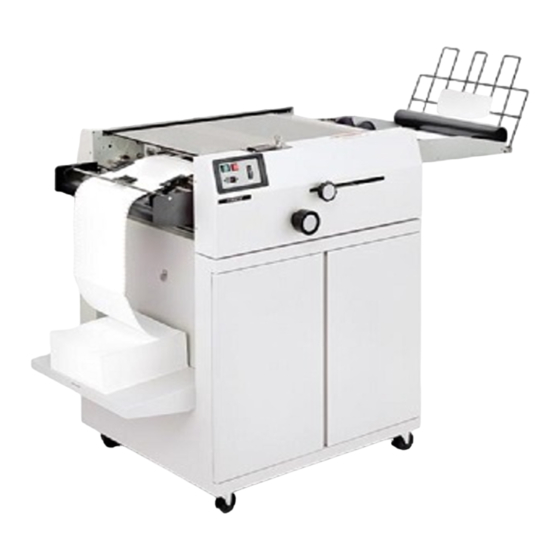
- Page 1 FD 540 Burster OPERATOR MANUAL FIRST EDITION...
-
Page 2: Table Of Contents
TABLE OF CONTENTS DESCRIPTION Function ....................1 Model Numbers ................1 Accessory Model Numbers .............. 1 Form Specifications ................. 1 Mounting Burster to Table ..............1 INSTALLATION Unpacking ..................2 Assembly ..................2 OPERATION General ................... 4 Safety ....................4 Control/Feature &... -
Page 3: Function
MOUNTING BURSTER TO THE TABLE Anti-Tenting Bracket 395-0015 This Burster is mounted to the table Center Slitter FD 540-77 1. FD540-60 with one hole intosurface of table. Install Power Stacker FD 540-80 “J” bolt in hole provided. Install washer and Table FD 540-60 wingnut loosely from underside of top surface. -
Page 4: Installation
INSTALLATION UNPACKING Do, not destroy the shipping cartons or materials until the machine has been inspected for shipping damage, missing parts, and proper operation. 1. Remove the bands and open the outer carton, 2. Remove the four corner blocks and open the inner carton. 3. - Page 5 6. Place the stacker wheel assembly on the stacker wheel adjustment rack. (Fig. 5) ASSEMBLY INSTRUCTIONS FOR INFEED BRUSH ASSEMBLY FOR FD546-40 AND FD546-50 ONLY Tools Required: Medium Phillips Screwdriver Parts Required: 1 - Infeed Brush Assembly (Packed with Burster) 4 - 6-32 Phillips Pan Head Screws (Packed in Accessory Box) 1.
-
Page 6: Operation
This section describes the controls, features, and normal but these devices do not replace good operative practices. operating procedures for the FD 540 Series Burster. This --Do not touch any moving parts while the machine is on. section also identifies and describes the control devices of the --Keep fingers, long hair, jewelry and loose clothing away... -
Page 7: Control/Feature & Function
CONTROL/FEATURE FUNCTION On/Off Switch Controls power to the Burster. Provides protection for the operator and the machine against accidental grounds or shorts. Indicator lights lets operator know that the power is Speed Control Varies burster speed. Start Switch Starts Burster. Stop Button Stops Burster. - Page 8 CONTROL/FEATURE FUNCTION Guide Wire Indicator Marks Indicates where the Guide wires are withing the machine Form Setting Indicator Enables the operator to quickly adjust the machine to the proper form length. Form Length Scale Form length can be measured in order to set the carriage adjustment.
-
Page 9: Form Set-Up Procedure With Slitters
FORM SET-UP PROCEDURE 1. Without table, machine should be positioned on an ordinary table with the Slitter Unit overhanging the edge. This will allow the paper edge trim to be directed into any type of basket placed under the Slitter Unit. 2. - Page 10 10. If necessary, readjust the position of the Feed 11. Close safety cover. Machine is now ready to Burst. Roller Carriage so that the form starts to burst when the Press start button and readjust machine speed to the perforation is just under the Tear Bar. fastest, yet smoothest Burst.
-
Page 11: Form Set-Up Procedure With Tractor & Slitters
SET-UP PROCEDURES FOR MODELS WITH SLITTERS SET-UP PROCEDURES FOR MODELS WITH SLITTERS AND FOLLOW FORM SET-UP PROCEDURES 1 THRU 9 AND TRACTORS PROCEED AS FOLLOWS. FOLLOW FORM SET-UP PROCEDURES 1 THRU 8 AND 1. Noting the Blade Indicator Marks on the Upper Guide table so PROCEED AND FOLLOWS. -
Page 13: Form Set-Up With Imprinter Slitters & Tractor Set-Up Procedures
IMPRINTER, SLITTERS AND TRACTORS SET-UP PROCEDURES NOTE: It is recommended that forms or checks fed into 7. Loosen Setscrews in Imprint Cylinder (if the Setscrews are not imprinter should be last form first, right side up. in plain view, use the Handwheel to bring them into plain view). 1. -
Page 14: Operating Hints
OPERATING HINTS 10. Turn Handwheel until Signature is printed on second check. 11. Located at the right end of the Imprint Cylinder shaft is the 1. Some paper has a natural curve. Sometimes thia curve tends timing collar. Loosen setscrew and align timing mark on Collar to catch air and sail. -
Page 15: Troubleshooting
TROUBLESHOOTING controls. Mechanical problems are usually accompanied by noise, slippage, tearing, or binds. If aform flow problem is present, jamming, misstacking Feeding, Bursting, and Stacking problems ar usually or intermittent form damage will occur. The problems due to improper adjustment of the machine to the forms should be diagnosed to one of the three categories or due to non-standaTd or defective. - Page 16 SYMPTOM PROBABLE CAUSE Large variation in trim accuracy. Upper/Lower Side Guides too loose/tight. Paper pack not centered to Slitter Infeed. Brush Tension to tight. Form pull out to tractors. Incorrect Burster roller timing. Incorrect Tear Bar setting. Insufficient Feed roller tension. Uneven Inking.
Need help?
Do you have a question about the FD 540 and is the answer not in the manual?
Questions and answers