
Related Manuals for WAGO 750 Series


Summary of Contents for WAGO 750 Series
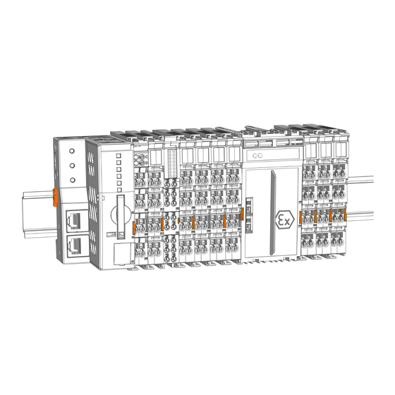
- Page 1 WAGO I/O System 750 Decentralized Automation Technology Serie 750, 753 System manual | Version 3.0.2...
- Page 2 We wish to point out that the software and hardware terms as well as the trademarks of companies used and/or mentioned in the present manual are generally protected by trademark or patent. WAGO is a registered trademark of WAGO Verwaltungsgesellschaft mbH. System manual | Version: 3.0.2...
-
Page 3: Table Of Contents
Serie 750, 753 Table of Contents Table of Contents Provisions......................... 5 Intended Use ...................... 5 Typographical Conventions.................. 6 Legal Information .................... 8 Safety .......................... 9 General Safety Regulations .................. 9 Electrical Safety....................... 9 Mechanical Safety .................... 10 Thermal Safety ...................... 10 Indirect Safety ....................... 10 System Features ...................... 11 Component Structure .................... - Page 4 Table of Contents Serie 750, 753 4.2.4 Buffering ....................... 29 4.2.5 Mounting Position .................. 29 4.2.6 DIN-Rail Characteristics ................ 31 4.2.7 EMC Installations .................. 31 4.2.8 Data Security .................... 32 Designing the System Supply ................ 33 Field Supply Layout.................... 33 Special Applications and Environments ...............
-
Page 5: Provisions
Note Observe the applicable documentation! This documentation is part of the complete Instructions for use for the WAGO I/O System 750/753. These products must only be installed and operated according to the instruc- tions of the complete Instructions for use. Knowledge of the complete Instructions for use is a precondition for intended use. -
Page 6: Typographical Conventions
The terms set forth in the General Business & Contract Conditions for Delivery and Ser- vice of WAGO Kontakttechnik GmbH & Co. KG and the terms for software products and products with integrated software stated in the WAGO Software License Contract – both ü www.wago.com... - Page 7 Serie 750, 753 Provisions “Value” Value entries [F5] Identification of buttons or keys Cross References / Links Cross references/links to a topic in a document Cross references / links to a separate document Þ Cross references / links to a website Cross references / links to an email address Action Instructions ü...
-
Page 8: Legal Information
Third-party products are always mentioned without any reference to patent rights. WAGO Kontakttechnik GmbH & Co. KG, or for third-party products, their manufacturer, retain all rights regarding patent, utility model or design registration. -
Page 9: Safety
Serie 750, 753 Safety Safety 2.1 General Safety Regulations • This documentation is part of the Products. Retain the documentation for the entire service life of the Products. Pass on the documentation to any subsequent user of the Products. In addition, ensure that any supplement to this documentation is included, if necessary. -
Page 10: Mechanical Safety
• If product fails, communication to downstream products may be interrupted. • Products from the WAGO I/O System 750/753 can be operated in combination with those of the WAGO I/O System 750 XTR. Such mixed operation does not change the maximum permissible ambient conditions of the individual products. -
Page 11: System Features
System Features System Features 3.1 Component Structure 3.1.1 Component Designs There are different housing forms in the WAGO I/O System 750. Head Stations The housings of head stations (fieldbus couplers or controllers) differ in: • The connection level – The power supply on the field level –... -
Page 12: Structure Of The Head Stations
System Features Serie 750, 753 3.1.2 Structure of the Head Stations Example PFC View Figure 3: Example PFC View Reset button & Product Manual Data contacts 8 Data Contacts [} 20] Display elements: Power supply status & Product Manual Display elements: System status &... - Page 13 Serie 750, 753 System Features Example View of the Fieldbus Coupler/Controller Figure 4: Example View of the Controller Slot for Mini-WSB (optional) 8 Data Contacts [} 20] Data contacts & Product Manual Display elements: Power supply status Display elements: Fieldbus status & Product Manual ®...
-
Page 14: I/O Module Configuration
System Features Serie 750, 753 3.1.3 I/O Module Configuration ® Example View of the I/O Module 750 Series (CAGE CLAMP Connections) ® Figure 5: I/O module 750 Series with CAGE CLAMP connections (example) Slot for WSB (optional) Data contacts 8 Data Contacts [} 20] Indicators &... - Page 15 Serie 750, 753 System Features ® Example View of the I/O Module 750 Series (Push-in CAGE CLAMP Connections) ® Figure 6: I/O module 750 Series with Push-in CAGE CLAMP connections (example) Slot for WSB (optional) Data contacts 8 Data Contacts [} 20] Indicators &...
- Page 16 System Features Serie 750, 753 Example View of the I/O Module 753 Series (Pluggable Connector) Figure 7: I/O module 753 Series (example) Slot for WSB (optional) Data contacts 8 Data Contacts [} 20] Indicators & Product Manual ® 8 Connect Conductor to CAGE CLAMP® [} 50] Access to open the associated CAGE CLAMP con- nection...
-
Page 17: Product Identification
WAGO I/O System 750 XTR Blue + dark gray WAGO I/O System 750 XTR – intrinsically safe modules (Ex i) Color Coding for Identifying Functionality To quickly and easily get an overview of the component classes present in a node, they are color-coded. -
Page 18: Marking Example
& Product Manual. CE mark The CE mark indicates WAGO has declared that the product conforms with the applicable requirements as set out in Community harmonization legislation per EC Regulation 765/2008, which allows the prod- uct to carry this mark. -
Page 19: Table 5 Explanation Of The Different Marking Example
“RCM” mark With the RCM marking (Regulatory Compliance Mark), WAGO declares in accordance with Aus- tralian standards that the product meets the appli- cable requirements. “CCC” mark... -
Page 20: Identification
System Features Serie 750, 753 Contents Description “EAC” icon The EAC mark indicates that the product conforms to the safety requirements set forth in the EEU technical requirements. “EAC Ex” icon The EAC Ex mark indicates that the product con- forms to the safety requirements set forth in the EEU technical requirements for operation in haz- ardous areas. -
Page 21: Power Jumper Contacts
Serie 750, 753 System Features Figure 8: Data Contacts 3.1.5.2 Power Jumper Contacts The field power supply is distributed in the I/O system via the power jumper contacts. The contacts on the left side are male contacts; those on the right side are touch-proof spring contacts. -
Page 22: Coding Keys
– If there is a power supply infeed, above the individual connections • On I/O modules of the 750 and 753 Series: – Above the indicators • On some I/O modules of the 750 Series: – Above the individual connections 3.2 Electrical Structure 3.2.1 Potential Groups... -
Page 23: System Supply
Serie 750, 753 System Features Example Potential Groups / Separation with Galvanically Separated Power Supply Infeed Figure 11: Display of Different Potential Groups System-level potential groups Field-level potential groups in right node section Field-level potential groups in left node section Fieldbus system potential groups 3.2.2 System Supply The system is supplied through the fieldbus coupler/controller and where needed, through additional supply modules with bus power supplies. - Page 24 • Use voltage sources with safe extra-low voltage (SELV, PELV). • Power must be supplied simultaneously to all system supply inputs. WAGO recommends using the same voltage source to realize the power supply. • Be sure maximum permissible current values are not exceeded.
-
Page 25: Field Supply
Serie 750, 753 System Features 3.2.3 Field Supply Figure 13: Field Supply Input (example) Observe the following requirements for the field supply: • Use voltage sources with safe extra-low voltage (SELV, PELV) for all voltages with a nominal value of 24 VDC. •... -
Page 26: Technical Data
You can find Product-specific information on the topic Guidelines, Standards and Recom- & Product mendations in the respective Manual. 3.4.3 Product-Related Environmental Protection Product-related environmental protection plays a significant role in WAGO's sustainable environmental management. We place high priority on ensuring adherence to substance prohibitions/limitations worldwide. System manual | Version: 3.0.2... - Page 27 The products manu- factured by WAGO are subject to the regulation. However, as articles are not subject to registration, WAGO usually assumes the role of the downstream user in the supply chain.
-
Page 28: Planning
• Fieldbus Technology Characteristics 4.2 Structure Guidelines 4.2.1 Installation Site and Touch-Proof Protection The WAGO I/O-System is an open system. As such, it must only be installed within ap- propriate housings, cabinets or electrical operation rooms that fulfill at least the following requirements:... -
Page 29: Overcurrent Protection
Serie 750, 753 Planning • Offer adequate protection against direct or indirect contact. • Offer adequate protection against UV irradiation. • Restrict access to authorized personnel and may only be opened with tools. • Ensure the required pollution degree in the vicinity of the system. •... - Page 30 Planning Serie 750, 753 Figure 14: Installation Clearances Coordinate Model Note Modified Coordinate Model In product documentation published before 2021, the height (y) and depth (z) have been swapped! • Width = Dimension along X axis = Horizontal in nominal mounting position; parallel to DIN-rail longitudinal axis •...
-
Page 31: Din-Rail Characteristics
Serie 750, 753 Planning Overview of Mounting Positions Nominal mounting position (horizon- Floor mounting position Ceiling mounting position tal left) Mounting position, horizontal right Mounting position, vertical top Mounting position, vertical bottom For vertical installation, always mount an end stop below the node to pre- vent it from slipping off. -
Page 32: Data Security
WAGO recommends putting control components and control networks behind a fire- wall. • In the control components, close all ports and services (e.g., for WAGO-I/O-CHECK and CODESYS) not required by your application to minimize the risk of cyber attacks and to enhance cybersecurity. -
Page 33: Designing The System Supply
& Product-specific information is available from the technical data in the respective Product Manual. For fast, effortless supply design, use the WAGO Smart Designer Configuration Software. 8 Aids A calculation example is available in [} 39]. 4.4 Field Supply Layout Designing the field supply requires knowledge of the entire field-side power consumption of the installed I/O modules. -
Page 34: Special Applications And Environments
Planning Serie 750, 753 4.5 Special Applications and Environments 4.5.1 Marine and Offshore The node structure must meet additional requirements to qualify for certified marine appli- cation. If these requirements are specific to an I/O module, they are described in the respective &... - Page 35 Serie 750, 753 Planning Example of a Power Supply Concept for Marine Applications - Class A and B per DNV GL Figure 16: Power Supply Concept for Marine Applications – Class A and B Filter module, 24 VDC, HI GF (750-626/020-002) or filter module, 24 VDC, HI (750-626/020-000) or filter module, 24 VDC, HI / T (750-626/025-001) Bus supply module, 24 VDC (750-602) or...
-
Page 36: Ex I Applications
Planning Serie 750, 753 Figure 17: Power Supply Concept for Marine Applications – Class A and B with FE Power Jumper Contact Head station Filter module, 24 VDC, HI GF (750-626/020-002) or filter module, 24 VDC, HI (750-626/020-000) or filter module, 24 VDC, HI / T (750-626/025-001) Bus supply module, 24 VDC (750-602) or bus supply module, 24 VDC, with fuse (750-601) or bus supply module, 24 VDC, with fuse and diagnostics (750-610) - Page 37 Serie 750, 753 Planning Figure 18: Ex i Power Supply Concept Ex i bus supply module (750-606, 750-625/000-001) Ex i I/O modules System supply (24 VDC) Field supply 1 (24 VDC) Field supply 2 (24 VDC) 750-606 with electronic fuse and diagnostics 750-625/000-001 with electronic fuse and no diagnostics Clearance and Creepage Distance Requirements For all sections of a node that contain I/O modules for Ex i use, stricter requirements re- garding clearances and creepage distances apply.
-
Page 38: Marine And Offshore Ex I Applications
Planning Serie 750, 753 If the following section consists of one end module (750-600), no distance modules are required. 4.5.3 Marine and Offshore Ex i Applications When I/O modules are used in marine Ex i applications, additional requirements must be considered alongside those described under 8 Ex i Applications [} 36] Ex i. -
Page 39: Examples And Aids
24 VDC, Ex i (750-625/000-001) Ex i I/O modules 4.6 Examples and Aids 4.6.1 Aids WAGO can help you with a wide range of useful products and software solutions. The aids for project planning include: System manual | Version: 3.0.2... -
Page 40: Table 10 Power Requirement: Example Calculation
• WAGO-I/O-CHECK Application for operating and displaying a node from the WAGO 750 I/O-SYSTEM Coding Multi-part I/O modules from the WAGO I/O-System can be equipped with coding keys to prevent mismatching when connecting the individual module parts. For additional information see: 8 Assembling/Disassembling Components... -
Page 41: I/O Test
Planning • I/O module: 1 W 4.6.2 I/O Test With the WAGO I/O System, it is possible to test your wiring simply and effectively using an I/O test. For example, WAGO software solutions such as e!COCKPIT and WAGO-I/O-CHECK make it possible to: •... -
Page 42: Transport And Storage
Transport and Storage Serie 750, 753 Transport and Storage The original packaging offers optimal protection during transport and storage. • Store the products in suitable packaging; preferably, in the original packaging. • Only transport the products in suitable containers/packaging. • Make sure the product contacts are not contaminated or damaged when packing or un- packing. -
Page 43: Assembly And Disassembly
Serie 750, 753 Assembly and Disassembly Assembly and Disassembly DANGER Do not work on products while energized! High voltage can cause electric shock or burns! • Disconnect all power sources from the product before performing any installation, re- pair or maintenance. Note Note planning documents! The structure of the node and installation in the system may only be carried out in accor-... -
Page 44: Attaching An I/O Module
Assembly and Disassembly Serie 750, 753 ð The head station is now locked on the DIN-rail. 6.3 Attaching an I/O Module 1. Position the I/O module in such a way that the grove and spring are connected to the preceding and following components. Figure 22: Inserting the I/O Module 2. -
Page 45: Removing A Head Station From The Din-Rail
Serie 750, 753 Assembly and Disassembly Attaching the 753 Series Wiring Interface Figure 24: 753 Series Wiring Interface and I/O Module 1. Make sure that the locking tab of the I/O module is not pulled out. 2. Put the wiring interface on the I/O module. 3. -
Page 46: Removing The I/O Module
An I/O module can be detached from the DIN-rail using its release tab and pulling it out of the assembly. Removing 750 Series I/O Modules 1. Pull up the orange release tab on the I/O module. To remove I/O modules with two release tabs from a group, both tabs must be pulled at the same time! Figure 26: Pull the release tab... - Page 47 Serie 750, 753 Assembly and Disassembly Figure 27: Pulling the Locking Latch 2. Pull up the orange release tab on the I/O module. Figure 28: Detaching the 753 Series I/O Module 3. Pull the I/O module out of the assembly by the release tab. ð...
-
Page 48: Assembling/Disassembling Components
Assembly and Disassembly Serie 750, 753 6.6 Assembling/Disassembling Components 6.6.1 Inserting Coding Keys For 753 Series I/O modules, the connection between the I/O module and the pluggable connector can be coded. For the coding, proceed as follows: 1. Insert the pin into the socket. Figure 29: Putting the Coding Keys Together 2. - Page 49 Serie 750, 753 Assembly and Disassembly Figure 32: Coding Keys for Clear Assignment System manual | Version: 3.0.2...
-
Page 50: Conductor Termination
Conductor Termination Serie 750, 753 Conductor Termination 7.1 Connect Conductor to CAGE CLAMP® ® ® CAGE CLAMP - and Push-in CAGE CLAMP Connectors are designed for solid, stranded and fine-stranded conductors. Solid, stranded and fine-stranded conductors are terminated by pushing them into Push- ®... -
Page 51: Decommissioning
Serie 750, 753 Decommissioning Decommissioning 8.1 Shutting Down 1. Bring the process to a secure stop. 2. Disconnect the respective system component from the power supply. 3. Check if the voltage is isolated. 4. Protect the system component from accidental or unauthorized restart. 5. -
Page 52: Appendix
® • Windows is a registered trademark of Microsoft Corporation. 9.2 Accessories Table 12: Recommended accessories Item No. Item Description Item Description WAGO DIN-Rails 210-1xx DIN-rails Steel bluish, galvanized, chromated; copper Buffer 787-8xx Capacitive buffer modules Capacitive buffer modules to bridge... - Page 53 Serie 750, 753 Appendix Item No. Item Description Item Description Shielding Elements Shield Connection System, 790 Se- See product catalog ries End Stops 249-1xx Screwless End Stop Tool 210-722 Operating tool set Operating Tool Set with Partially In- sulated Shaft Test Probes 735-500 Test pin...
- Page 54 List of Tables Serie 750, 753 List of Tables Table 1 Complete instructions for use ................... Table 2 Color coding of Component Types ..................Table 3 Color coding of component classes ................... Table 4 Explanation of the Marking Example ................. Table 5 Explanation of the Different Marking Example..............
- Page 55 Example View of the Controller..................Figure 5 I/O module 750 Series with CAGE CLAMP® connections (example) ......Figure 6 I/O module 750 Series with Push-in CAGE CLAMP® connections (example) ..... Figure 7 I/O module 753 Series (example) ................. Figure 8 Data Contacts ......................
- Page 56 WAGO is a registered trademark of WAGO Verwaltungsgesellschaft mbH. Copyright – WAGO Kontakttechnik GmbH & Co. KG – All rights reserved. The content and structure of the WAGO websites, catalogs, videos and other WAGO media are subject to copyright. Distribution or modification of the contents of these pages and videos is prohibited. Furthermore, the content may neither be copied nor made available to third parties for...
Need help?
Do you have a question about the 750 Series and is the answer not in the manual?
Questions and answers