Table of Contents
Advertisement
Quick Links
Pos : 2 /D okumentati on allgemein/Ei nband/Ei nband H andbuch - Dec kbl att ohne Variantenfel d (Standar d) @ 9\mod_1285229289866_0.doc x @ 64941 @ @ 1
Manual
WAGO-I/O-SYSTEM 750
Serial Interface RS-232 / RS-485
750-652
Configurable
1.2.0
Pos : 3 /Alle Serien (Allgemeine M odul e)/Hinweise z ur Dokumentation/Impres sum für Standardhandbüc her - allg. Angaben, Ansc hriften, Tel efonnummer n und E-Mail-Adres sen @ 3\mod_1219151118203_21.doc x @ 21060 @ @ 1
Advertisement
Chapters
Table of Contents

Related Manuals for WAGO 750 Series


Summary of Contents for WAGO 750 Series
- Page 1 Pos : 2 /D okumentati on allgemein/Ei nband/Ei nband H andbuch - Dec kbl att ohne Variantenfel d (Standar d) @ 9\mod_1285229289866_0.doc x @ 64941 @ @ 1 Manual WAGO-I/O-SYSTEM 750 Serial Interface RS-232 / RS-485 750-652 Configurable 1.2.0 Pos : 3 /Alle Serien (Allgemeine M odul e)/Hinweise z ur Dokumentation/Impres sum für Standardhandbüc her - allg. Angaben, Ansc hriften, Tel efonnummer n und E-Mail-Adres sen @ 3\mod_1219151118203_21.doc x @ 21060 @ @ 1...
- Page 2 WAGO-I/O-SYSTEM 750 750-652 Serial Interface RS-232 / RS-485 © 2013 by WAGO Kontakttechnik GmbH & Co. KG All rights reserved. WAGO Kontakttechnik GmbH & Co. KG Hansastraße 27 D-32423 Minden Phone: +49 (0) 571/8 87 – 0 Fax: +49 (0) 571/8 87 – 1 69 E-Mail: info@wago.com...
-
Page 3: Table Of Contents
Subject to Changes ................10 2.1.2 Personnel Qualifications ..............10 2.1.3 Use of the 750 Series in Compliance with Underlying Provisions ..10 2.1.4 Technical Condition of Specified Devices ......... 11 Safety Advice (Precautions) ..............12 Device Description ..................14 View ...................... - Page 4 7.2.4 DMX Operating Mode ............... 45 7.2.5 Data Exchange Mode ................. 46 Commissioning ................... 47 Configuration and Parameterization with WAGO-I/O-CHECK ..... 47 8.1.1 RS-232 / RS-485 Serial Interface (Configuration Dialog) ....47 8.1.2 Toolbar on the Configuration Dialog ..........48 8.1.3...
- Page 5 WAGO-I/O-SYSTEM 750 Table of Contents 750-652 Serial Interface RS-232 / RS-485 10.2.2 Special conditions for safe use (ATEX Certificate TÜV 07 ATEX 554086 X) ................... 68 10.2.3 Special conditions for safe use (IEC-Ex Certificate TUN 09.0001 X)70 10.2.4 ANSI/ISA 12.12.01 ................72 Appendix .....................
-
Page 6: Notes About This Documentation
Pos : 11 /Serie 750 ( WAGO-I/O-SYST EM)/Hi nweis e z ur D okumentati on/Variantenlisten/Variantenliste - 750- xxx - Standardversion und Variante /025- 000 ( erweiterter Temperaturbereic h) @ 9\mod_1281521920414_21.doc x @ 63093 @ @ 1... -
Page 7: Symbols
WAGO-I/O-SYSTEM 750 Notes about this Documentation 750-652 Serial Interface RS-232 / RS-485 Pos : 14.2 /Dokumentation allgemei n/Glieder ungs elemente/---Seitenwechs el--- @ 3\mod_1221108045078_0.doc x @ 21810 @ @ 1 Pos : 14.3 /All e Seri en ( Allgemei ne Module)/Ü bers chriften für alle Serien/Hinweis z ur D okumentati on/Symbole - Ü berschrift 2 @ 13\mod_1351068042408_21.doc x @ 105270 @ 2 @ 1 Symbols Pos : 14.4.1 /All e Serien ( Allgemei ne Module)/Wic htige Erläuterungen/Sicherheits- und sons tige Hinweis e/Gefahr/Gefahr: _War nung vor Personenschäden allgemei n_ - Erl äuter ung @ 13\mod_1343309450020_21.doc x @ 101029 @ @ 1... - Page 8 Notes about this Documentation WAGO-I/O-SYSTEM 750 750-652 Serial Interface RS-232 / RS-485 Additional Information: Refers to additional information which is not an integral part of this documentation (e.g., the Internet). Pos : 14.5 /Dokumentation allgemei n/Glieder ungs elemente/---Seitenwechs el--- @ 3\mod_1221108045078_0.doc x @ 21810 @ @ 1 Manual 1.2.0...
-
Page 9: Number Notation
WAGO-I/O-SYSTEM 750 Notes about this Documentation 750-652 Serial Interface RS-232 / RS-485 Pos : 14.6 /All e Seri en ( Allgemei ne Module)/Hi nweis e zur D okumentati on/Zahlens ysteme @ 3\mod_1221059454015_21.doc x @ 21711 @ 2 @ 1 Number Notation... -
Page 10: Important Notes
All changes to the coupler or controller should always be carried out by qualified personnel with sufficient skills in PLC programming. Pos : 17.5 /Serie 750 (WAGO-I/O-SYST EM)/Wic htige Erläuterungen/Bes timmungsgemäß e Verwendung 750- xxxx @ 3\mod_1224064151234_21.doc x @ 24070 @ 3 @ 1 2.1.3... -
Page 11: Technical Condition Of Specified Devices
The components to be supplied Ex Works, are equipped with hardware and software configurations, which meet the individual application requirements. WAGO Kontakttechnik GmbH & Co. KG will be exempted from any liability in case of changes in hardware or software as well as to non-compliant usage of components. -
Page 12: Safety Advice (Precautions)
Pos : 17.10.2 /Serie 750 ( WAGO-I/O- SYST EM)/Wic htig e Erl äuter ung en/Sic her hei ts- und s onstige Hi nweise/Gefahr/Gefahr: Ei nbau 0750- xxxx nur i n Gehäus en, Sc hränken oder el ektrisc hen Betriebsräumen! @ 6\mod_1260180556692_21.doc... - Page 13 WAGO-I/O-SYSTEM 750 Important Notes 750-652 Serial Interface RS-232 / RS-485 Do not use any contact spray! Do not use any contact spray. The spray may impair contact area functionality in connection with contamination. Pos : 17.11.5 /Alle Serien (Allgemeine D okumente) (Allgemeine M odul e)/Wichtige Erläuter ungen/Sic herheits hinweise/Ac htung/Ac htung: Verpol ung ver mei den! @ 6\mod_1260184045744_21.doc x @ 46767 @ @ 1...
-
Page 14: Device Description
115200 baud. Pos : 20.2 /Serie 750 (WAGO-I/O-SYST EM)/Ger ätebesc hrei bung/Ei nlei tung/Anwendung/SOAnwendung 750- 0652 D atenfluss steuerung, D atenaustausch und DMX-M odus @ 15\mod_1366289566565_21.doc x @ 117314 @ @ 1 In the data flow control through RTS/CTS in RS-232 mode, a lead time or follow- on time can be configured for the I/O module for the RTS signal. - Page 15 485/RS-422 mode via the connections A, B, X, Y, and ground. Pos : 20.4 /Serie 750 (WAGO-I/O-SYST EM)/Ger ätebesc hrei bung/Ei nlei tung/I/O-Besc hrei bung/AI/I/O- Bes chr eibung 750- 04xx AI Schir mans chl uss Kontakt mit Tr agsc hiene @ 5\mod_1246367742653_21.doc x @ 36360 @ @ 1 The shield connection is fed directly to the carrier rail and contact is made automatically by snapping the module onto the rail.
-
Page 16: Table 4: Compatibility List 750-0652
750-652 Serial Interface RS-232 / RS-485 Pos : 22 /Serie 750 ( WAGO-I/O-SYST EM)/Ger ätebesc hrei bung/Ei nlei tung/Ei ns atz ber eich/Ei ns atz ber eich 750- xxxx nur Koppl er/C ontr oller aus Kompatibilitätsliste @ 4\mod_1242389440265_21.doc x @ 33262 @ @ 1... - Page 17 WAGO-I/O-SYSTEM 750 Device Description 750-652 Serial Interface RS-232 / RS-485 CANopen Fieldbus couplers 750-337 750-338 ECO fieldbus coupler 750-347 750-348 Programmable 750-837 fieldbus controller 750-838 I/O-IPC 758-870/ 000-112 758-875/ 000-112 Programmable 750-849 fieldbus controller BACnet Programmable 750-830 fieldbus controller LONWORKS...
-
Page 18: View
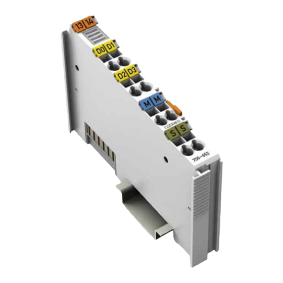
Pos : 25 /All e Seri en (Allgemei ne Module)/Ü berschriften für alle Serien/Gerätebesc hreibung/Ansic ht - Ü berschrift 2 @ 4\mod_1240984217343_21.doc x @ 31958 @ 2 @ 1 View Pos : 26 /Serie 750 ( WAGO-I/O-SYST EM)/Ger ätebesc hrei bung/Ansic ht/Sonder klemmen/Ansic ht 750- 0652 @ 6\mod_1263997977704_21.doc x @ 48200 @ @ 1 Figure 1: View Table 5: Legend for "View"... -
Page 19: Connectors
Pos : 30.3 /Serie 750 (WAGO-I/O-SYST EM)/Wic htige Erläuterungen/Sicherheits- und sonstig e Hinweis e/Achtung/Achtung: ESD - Auf g ute Erdung der U mgebung ac hten! @ 7\mod_1266318538667_21.doc x @ 50708 @ @ 1 Ensure that the environment is well grounded! The modules are equipped with electronic components that may be destroyed by electrostatic discharge. -
Page 20: Power Jumper Contacts/Field Supply
Pos : 33.3 /Serie 750 (WAGO-I/O-SYST EM)/Ger ätebesc hrei bung/Ansc hl üsse/Leistungs kontakte 2 LK (Mess er/Leis tungs kontakte 2 LK (Messer /Feder) - Abbil dung (ei nfac he Brei te) @ 15\mod_1367500700037_21.doc x @ 118396 @ @ 1 Figure 3: Power jumper contacts Pos : 33.4 /Serie 750 (WAGO-I/O-SYST EM)/Ger ätebesc hrei bung/Ansc hl üsse/Leistungs kontakte 2 LK (Mess er/Leis tungs kontakte 2 LK (Messer /Feder) - Legende @ 15\mod_1371721352500_21.doc x @ 123710 @ @ 1... - Page 21 WAGO-I/O-SYSTEM 750 Device Description 750-652 Serial Interface RS-232 / RS-485 Use potential feed module for Ground (earth)! The I/O module has no power contacts for PE intake and transfer. Use a potential feed module when a PE feed is needed for the subsequent I/O modules.
-
Page 22: Cage Clamp Connectors
WAGO-I/O-SYSTEM 750 750-652 Serial Interface RS-232 / RS-485 Pos : 35 /Serie 750 ( WAGO-I/O-SYST EM)/Ger ätebesc hrei bung/Ansc hl üss e/CAGE CLAMP- Anschl üss e - Ü berschrift 3 @ 6\mod_1256296337770_21.doc x @ 43674 @ 3 @ 1 ®... -
Page 23: Display Elements
Pos : 39 /All e Seri en (Allgemei ne Module)/Ü berschriften für alle Serien/Gerätebesc hreibung/Anz eigeel emente - Übersc hrift 2 @ 4\mod_1240984390875_21.doc x @ 31964 @ 2 @ 1 Display Elements Pos : 40 /Serie 750 ( WAGO-I/O-SYST EM)/Ger ätebesc hrei bung/Anz eigeelemente/Sonder klemmen/Anz eigeel emente 750- 0652_D atenaustausch @ 13\mod_1352285645747_21.doc x @ 105634 @ @ 1 Table 8: Display elements... -
Page 24: Operating Elements
Operating Elements Pos : 42 /Serie 750 ( WAGO-I/O-SYST EM)/Ger ätebesc hrei bung/Bedienel emente/Bedi enel emente Bus kl emme 750- xxxx nic ht vor handen @ 4\mod_1236322031125_21.doc x @ 28063 @ @ 1 The I/O module 750-652 has no operating elements. -
Page 25: Technical Data
Pos : 46 /All e Seri en (Allgemei ne Module)/Ü berschriften für alle Serien/Gerätebesc hreibung/Technisc he Daten - Ü berschrift 2 @ 3\mod_1232967587687_21.doc x @ 26924 @ 2 @ 1 Technical Data Pos : 47 /Serie 750 ( WAGO-I/O-SYST EM)/Ger ätebesc hrei bung/T echnisc he Daten/Sonder kl emmen/T ec hnische D aten 750-0652_Datenaus tausc h @ 13\mod_1352288102167_21.doc x @ 105678 @ 3333 @ 1 3.6.1... -
Page 26: Interface
Pos : 48 /Serie 750 ( WAGO-I/O-SYST EM)/Ger ätebesc hrei bung/T echnisc he Daten/T ec hnische D aten Kli matisc he U mwel tbedi ngungen m. er w. Tempber eich; 0...55°C /-20...+60°C/- 25...+ 85°C @ 5\mod_1247658089120_21.doc... -
Page 27: Approvals
Pos : 51 /Serie 750 ( WAGO-I/O-SYST EM)/Ger ätebesc hrei bung/Z ulass ungen/Allgemei n/Z ulass ungen Bus kl emme 750- xxxx Allgemein, Standardversi on und all e Vari anten - Einl eitung @ 3\mod_1233911570312_21.doc x @ 27390 @ @ 1... -
Page 28: Process Image
Process Image Pos : 66 /Serie 750 ( WAGO-I/O-SYST EM)/Proz ess abbild Kl emmenbus /Hinweis: Prozes sabbildmapping abhängig von FBK/PFC, mit Status-/C ontroll byte @ 4\mod_1242621308640_21.doc x @ 33290 @ @ 1 Mapping of process data in the process image of fieldbus systems The representation of the process data of some I/O modules or their variations in the process image depends on the fieldbus coupler/controller used. -
Page 29: Table 15: Control Byte C0
WAGO-I/O-SYSTEM 750 Process Image 750-652 Serial Interface RS-232 / RS-485 Table 15: Control byte C0 Bit 7 Bit 6 Bit 5 Bit 4 Bit 3 Bit 2 Bit 1 Bit 0 Transmit request Receive acknowledge Initialization request Send continuous (of data from the FIFO) -
Page 30: Data Exchange Mode
Process Image WAGO-I/O-SYSTEM 750 750-652 Serial Interface RS-232 / RS-485 Table 18: Status byte S1 Bit 7 Bit 6 Bit 5 Bit 4 Bit 3 Bit 2 Bit 1 Bit 0 BUF_E Input length (number of characters received that are available in the input data,... -
Page 31: Table 20: Control Byte C0
WAGO-I/O-SYSTEM 750 Process Image 750-652 Serial Interface RS-232 / RS-485 Table 20: Control byte C0 Bit 7 Bit 6 Bit 5 Bit 4 Bit 3 Bit 2 Bit 1 Bit 0 Initialization/reset (If the bit is set, the module is in the reset state. -
Page 32: Function Description
Operating Modes for Serial Transmission Pos : 70.2 /Serie 750 (WAGO-I/O-SYST EM)/F unktions beschr eibungFunkti ons besc hreibung 750-0652 - Betriebs arten für s eriell e Ü bertr agung @ 14\mod_1363001336668_21.doc x @ 114123 @ 34343444333 @ 1 In den In the operating modes for serial transmission, the I/O module allows communication with serial devices via RS-232, RS-485, RS-422 or DMX. -
Page 33: Receive Data
WAGO-I/O-SYSTEM 750 Function Description 750-652 Serial Interface RS-232 / RS-485 If continuous transmission is activated, the I/O module evaluates the bit SC in control byte 0. Only when SC takes the value 1 does the I/O module transmit the data contained in the output buffer to the serial interface. The application can set SC to 0 to prompt the I/O module to accumulate data in the output buffer. -
Page 34: Rs-232 Operating Mode
Function Description WAGO-I/O-SYSTEM 750 750-652 Serial Interface RS-232 / RS-485 5.1.3 RS-232 Operating Mode The RS-232 operating mode in full-duplex is realized in a 2-wire or 4-wire point- to-point connection. Simultaneous transmission and receiving is possible. In this mode, the I/O module supports flow control for the serial interface. The I/O... -
Page 35: Rs-485 Operating Mode
WAGO-I/O-SYSTEM 750 Function Description 750-652 Serial Interface RS-232 / RS-485 5.1.4 RS-485 Operating Mode The RS-485 operating mode in half-duplex is realized in a 2-wire multi-endpoint (bus) connection. Simultaneous transmission and receiving is not possible with 2-wire connections. The I/O module switches to receive mode after transmitting the content of the input buffer to the serial interface completely. -
Page 36: Data Exchange Operating Mode
Data Exchange Operating Mode Pos : 70.4 /Serie 750 (WAGO-I/O-SYST EM)/F unktions beschr eibungFunkti ons besc hreibung 750-0652 - Betriebs art D atenaustaus ch @ 15\mod_1365154044596_21.doc x @ 116646 @ @ 1 The Data Exchange operating mode is also available with firmware version 03 or higher. - Page 37 WAGO-I/O-SYSTEM 750 Function Description 750-652 Serial Interface RS-232 / RS-485 The cycle, in which process data is exchanged between I/O modules, is event driven. The I/O module only starts the next transmission after assessing the transmission of the opposite side as error-free. The I/O module then also begins a new transmission if no error-free transmission has been received from the opposite side for a period of at least 200 ms.
-
Page 38: Mounting
Pos : 73.2 /Serie 750 (WAGO-I/O-SYST EM)/Wic htige Erläuterungen/Sicherheits- und sonstig e Hinweis e/Vorsic ht/Vorsicht: Verl etz ungsgefahr durc h s charfkantige M ess er kontakte! @ 6\mod_1256193279401_21.doc x @ 43414 @ @ 1 Risk of injury due to sharp-edged male contacts! The male contacts are sharp-edged. -
Page 39: Inserting And Removing Devices
Inserting and Removing Devices Pos : 73.8 /Serie 750 (WAGO-I/O-SYST EM)/Wic htige Erläuterungen/Sicherheits- und sonstig e Hinweis e/Gefahr/Gefahr : Vorsic ht bei der U nterbr echung von F E! @ 6\mod_1256193919214_21.doc x @ 43423 @ @ 1 Use caution when interrupting the PE! Make sure that people or equipment are not placed at risk when removing an I/O module and the associated PE interruption. -
Page 40: Removing The I/O Module
(if any) to the fieldbus coupler/controller or to the previous or possibly subsequent I/O module are established. Pos : 73.11 /Serie 750 ( WAGO-I/O-SYST EM)/Monti eren/Bus kl emme entfer nen @ 4\mod_1239169375203_21.doc x @ 30334 @ 3 @ 1 6.2.2 Removing the I/O Module Remove the I/O module from the assembly by pulling the release tab. -
Page 41: Connect Devices
Pos : 77 /Serie 750 ( WAGO-I/O-SYST EM)/Ans chli eßen/Leiter an C AGE C LAM P ans chli eßen - Ü berschrift 2 und T ext @ 3\mod_1225448660171_21.doc x @ 24928 @ 2 @ 1 ®... -
Page 42: Connection Examples
Pos : 78 /All e Seri en (Allgemei ne Module)/Ü berschriften für alle Serien/Ansc hließ en/Ans chl uss beis piel e - Ü berschrift 2 @ 4\mod_1240996036328_21.doc x @ 32010 @ 2 @ 1 Connection Examples Pos : 79 /Serie 750 ( WAGO-I/O-SYST EM)/Ans chli eßen/Anschl uss beispi ele/Sonderkl emmen/Ansc hluss beispi ele 750-0652_Datenaustausc h @ 13\mod_1352292796190_21.doc x @ 105682 @ 33333 @ 1 7.2.1... -
Page 43: Rs-485 Operating Mode
WAGO-I/O-SYSTEM 750 Connect Devices 750-652 Serial Interface RS-232 / RS-485 7.2.2 RS-485 Operating Mode Figure 13: Bus connection RS-485 operating mode, half-duplex In the RS-485 operating mode (bus connection), a twisted-pair cable should be used at least for larger cable lengths or higher transmission rates. The ends of the cable should be terminated with a terminal resistor. -
Page 44: Figure 14: Bus Connection Rs-485 Operating Mode With Biasing Network, Half-Duplex
Connect Devices WAGO-I/O-SYSTEM 750 750-652 Serial Interface RS-232 / RS-485 Figure 14: Bus connection RS-485 operating mode with Biasing network, half-duplex With the use of the biasing resistors, it is guaranteed in this case that all receiver inputs A have the voltage difference of more than 200 mV to the inputs B if no transmitter is active. -
Page 45: Rs-422 Operating Mode
WAGO-I/O-SYSTEM 750 Connect Devices 750-652 Serial Interface RS-232 / RS-485 7.2.3 RS-422 Operating Mode Figure 15: Bus connection RS-422 operating mode For the RS-422 operating mode (point-to-point connection), the bus ends (at least for longer line lengths and greater baud rates) should be terminated with a terminal resistor. -
Page 46: Data Exchange Mode
Connect Devices WAGO-I/O-SYSTEM 750 750-652 Serial Interface RS-232 / RS-485 7.2.5 Data Exchange Mode Figure 16: Point-to-point connection between two nodes In this mode, the contacts of the I/O modules to connect are connected to each other crosswise. In the Data Exchange operating mode (point-to-point connection), a twisted-pair cable should be used at least for larger cable lengths. -
Page 47: Commissioning
Commissioning Pos : 82.1 /Serie 759 (WAGO-Softwar e)/WAGO-I/O-CHEC K/750- 0652 Seriell e Schnittstelle R S-232/RS- 485_Datenaus tausc hSeriell e Schnittstelle R S-232/RS- 485 750- 0652 (Parametrier dial og) @ 14\mod_1361195989708_21.doc x @ 112203 @ 23 @ 1 Configuration and Parameterization with... -
Page 48: Toolbar On The Configuration Dialog
Status reports are output in the status display in the lower area of the configuration dialog. Pos : 82.2 /Serie 759 (WAGO-Softwar e)/WAGO-I/O-CHEC K/750- 0652 Seriell e Schnittstelle R S-232/RS- 485_Datenaus tausc hSeriell e Schnittstelle R S-232/RS- 485 750- 0652 (Symbolleiste) @ 14\mod_1361196248892_21.doc x @ 112207 @ 3 @ 1 8.1.2... -
Page 49: Process Image Size
Opens the WAGO-I/O-CHECK online help. Pos : 82.3 /Serie 759 (WAGO-Softwar e)/WAGO-I/O-CHEC K/750- 0652 Seriell e Schnittstelle R S-232/RS- 485_Datenaus tausc hSeriell e Schnittstelle R S-232/RS- 485 750- 0652 (PA-Grösse) @ 14\mod_1361196391363_21.doc x @ 112211 @ 3 @ 1 8.1.3 Process Image Size To make settings on the "PI Mapping"... -
Page 50: Parameter Range
750-652 Serial Interface RS-232 / RS-485 Pos : 82.4 /Serie 759 (WAGO-Softwar e)/WAGO-I/O-CHEC K/750- 0652 Seriell e Schnittstelle R S-232/RS- 485_Datenaus tausc hSeriell e Schnittstelle R S-232/RS- 485 750- 0652 (Parameter Ei nstellungen) @ 14\mod_1361196481276_21.doc x @ 112215 @ 3 @ 1 8.1.4... -
Page 51: Setting The Rs-232 / Rs-485 Serial Interface
Flow control: RTS with lead/follow-on time Pos : 82.5 /Serie 759 (WAGO-Softwar e)/WAGO-I/O-CHEC K/750- 0652 Seriell e Schnittstelle R S-232/RS- 485_Datenaus tausc hSeriell e Schnittstelle R S-232/RS- 485 750- 0652 (Bedienung) @ 14\mod_1361457184342_21.doc x @ 112650 @ 32 @ 1 8.1.5... -
Page 52: Configuration And Parameterization Via Gsd For Profibus Dp And Profinet Io
Commissioning WAGO-I/O-SYSTEM 750 750-652 Serial Interface RS-232 / RS-485 Input operating mode! In case of a change of operating mode, a warning appears that points out that it may be necessary to change the wiring. Configuration and Parameterization via GSD for... -
Page 53: Initialization
WAGO-I/O-SYSTEM 750 Commissioning 750-652 Serial Interface RS-232 / RS-485 Reset initialization bit! The initialization bit in control byte C0 must be reset. As long as the initialization bit is set, no data is exchanged. The initialization bit can be reset simultaneously with transmission of the initial data. -
Page 54: Transmission Of The Character String "Hello World
8.3.4 Receiving the Character String "WAGO" As soon as RA ≠ RR, characters are available in the input byte. Table 32: Output process image Control byte 0 Control byte 1... -
Page 55: Operation With Continuous Send
WAGO-I/O-SYSTEM 750 Commissioning 750-652 Serial Interface RS-232 / RS-485 Table 33: Receive data Status byte 0 Status byte 1 Input byte 0 Input byte 1 0-xxx X (00x) '0XXX. 1XXX' There are no receive data available. '0XX1. 001X' '0XXX. 1XXX' "W"... -
Page 56: Transmission Of A Block Of More Than 512 Bytes
Commissioning WAGO-I/O-SYSTEM 750 750-652 Serial Interface RS-232 / RS-485 Table 37: Transmission of a block of one to 512 bytes Control byte 0 Control byte 1 '0110.1001' '0XXX. X101' Controller fills the output buffer with 46 bytes and set bit 3 (SC) of the control byte 0 for the start of the transmission. -
Page 57: Table 38: Transmission Of A Block Of More Than 512 Bytes
WAGO-I/O-SYSTEM 750 Commissioning 750-652 Serial Interface RS-232 / RS-485 Table 38: Transmission of a block of more than 512 bytes Control byte 0 Control byte 1 '0110.1001' '0XXX. X101' Controller fills the output buffer with 46 bytes and set bit 3 (SC) of the control byte 0 for the start of the transmission. -
Page 58: Dmx Application Example
Commissioning WAGO-I/O-SYSTEM 750 750-652 Serial Interface RS-232 / RS-485 8.3.6 DMX Application Example 8.3.6.1 Operation with Deactivated Continuous Send In this mode, the I/O module only transmits the data for a limited number of DMX channels according to the set size of the process image (see table "Process data in the DMX operating mode without continuous send"). -
Page 59: Data Exchange Operating Mode Application Example
WAGO-I/O-SYSTEM 750 Commissioning 750-652 Serial Interface RS-232 / RS-485 8.3.7 Data Exchange Operating Mode Application Example In the "Data Exchange" operating mode, the I/O module monitors process data exchange with the partner module. If the connection is interrupted for 200 ms or more, it generates a diagnosis in the status byte. -
Page 60: Diagnostics
Pos : 84 /All e Seri en (Allgemei ne Module)/Ü berschriften für alle Serien/Diag nos e - Ser vice/Diagnos e - Ü bers chrift 1 @ 4\mod_1240831069471_21.doc x @ 31372 @ 1 @ 1 Diagnostics Pos : 85 /Serie 750 ( WAGO-I/O-SYST EM)/Di agnose/Bus kl emmen/Di agnose 750-0652_D atenaustausc h @ 15\mod_1365143340308_21.doc x @ 116640 @ 22 @ 1 Serial Operating Modes... -
Page 61: Use In Hazardous Environments
Use in Hazardous Environments Pos : 86.2 /Serie 750 (WAGO-I/O-SYST EM)/Eins atz in Ex- Ber eichen/Ei ns atz ber eich Serie 750 @ 3\mod_1234272230203_21.doc x @ 27500 @ @ 1 The WAGO-I/O-SYSTEM 750 (electrical equipment) is designed for use in Zone 2 hazardous areas. -
Page 62: Marking Configuration Examples
Marking for Europe according to ATEX and IEC-Ex Pos : 86.6 /Serie 750 (WAGO-I/O-SYST EM)/Eins atz in Ex- Ber eichen/Beis piel bedruc kung der ATEX- und IEC- Ex-zug elass enen Bus klemmen gemäß C ENELEC und IEC @ 7\mod_1274340031573_21.doc x @ 56687 @ @ 1... -
Page 63: Figure 23: Side Marking Example For Ex I And Iec Ex I Approved I/O Modules
750-652 Serial Interface RS-232 / RS-485 Pos : 86.8 /Serie 750 (WAGO-I/O-SYST EM)/Eins atz in Ex- Ber eichen/Beis piel bedruc kung der Ex-i- und IEC-Ex-i-zug elas senen Bus klemmen gemäß C ENELEC und IEC @ 7\mod_1274338578856_21.doc x @ 56679 @ @ 1... -
Page 64: Table 43: Description Of Marking Example For Ex I And Iec Ex I Approved I/O Modules According To Cenelec And Iec
Use in Hazardous Environments WAGO-I/O-SYSTEM 750 750-652 Serial Interface RS-232 / RS-485 Table 43: Description of marking example for Ex i and IEC Ex i approved I/O modules according to CENELEC and IEC Inscription text Description TÜV 07 ATEX 554086 X Approving authority or TUN 09.0001X... -
Page 65: Marking For America According To Nec 500
750-652 Serial Interface RS-232 / RS-485 Pos : 86.10 /Serie 750 ( WAGO-I/O-SYST EM)/Ei ns atz i n Ex-Bereic hen/Kennz eichnung für Ameri ka gemäß N EC 500 - Übersc hrift 3 @ 3\mod_1224158423187_21.doc x @ 24188 @ 3 @ 1 10.1.2... -
Page 66: Installation Regulations
Pos : 86.17 /D okumentati on allgemei n/Gli ederungsel emente/------Leerz eile------ @ 3\mod_1224662755687_0.doc x @ 24460 @ @ 1 Pos : 86.18 /Serie 750 ( WAGO-I/O-SYST EM)/Ei ns atz i n Ex-Bereic hen/Ac htung: Errichtungsbes timmungen Serie 750 beachten @ 3\mod_1224158893890_21.doc x @ 24191 @ @ 1... -
Page 67: Special Conditions For Safe Operation Of The Atex And Iec Ex (Acc. Demko 08 Atex 142851X And Iecex Ptb 07.0064)
Pos : 86.20 /Serie 750 ( WAGO-I/O-SYST EM)/Ei ns atz i n Ex-Bereic hen/Besonder e Beding ung en für den sic her en AT EX- und IEC-Ex-Betri eb gem. D EMKO 08 ATEX 142851X & IEC Ex @ 7\mod_1274277358920_21.doc... -
Page 68: Special Conditions For Safe Use (Atex Certificate Tüv 07 Atex 554086 X)
Pos : 86.22 /Serie 750 ( WAGO-I/O-SYST EM)/Ei ns atz i n Ex-Bereic hen/Besonder e Beding ung en für den sic her en Ex- Betrieb gem. AT EX-Z ertifi kat TÜV 07 ATEX 554086 X @ 12\mod_1340262566733_21.doc... - Page 69 WAGO-I/O-SYSTEM 750 Use in Hazardous Environments 750-652 Serial Interface RS-232 / RS-485 Pos : 86.24 /Alle Serien (Allgemeine M odul e)/Ei ns atz i n Ex-Bereic hen/Hinweisanhang - In der Nähe des Gerätes sind die folgenden Warnhi nweis e anzubringen: @ 11\mod_1326966656062_21.doc x @ 86612 @ @ 1 The following warnings shall be placed nearby the unit: Pos : 86.25 /Alle Serien (Allgemeine M odul e)/Wichtige Erläuterungen/Sic herheits- und s onstige Hinweise/War nung/War nung: Sic her ung nic ht unter Spannung heraus nehmen oder wechs eln! @ 11\mod_1326959227633_21.doc x @ 86570 @ @ 1...
-
Page 70: Special Conditions For Safe Use (Iec-Ex Certificate Tun 09.0001
Pos : 86.29 /Serie 750 ( WAGO-I/O-SYST EM)/Ei ns atz i n Ex-Bereic hen/Besonder e Beding ung en für den sic her en Ex- Betrieb gem. IEC-Ex-Z ertifi kat TUN 09.0001 X @ 12\mod_1340260483271_21.doc... - Page 71 WAGO-I/O-SYSTEM 750 Use in Hazardous Environments 750-652 Serial Interface RS-232 / RS-485 Pos : 86.31 /Alle Serien (Allgemeine M odul e)/Ei ns atz i n Ex-Bereic hen/Hinweisanhang - In der Nähe des Gerätes sind die folgenden Warnhi nweis e anzubringen: @ 11\mod_1326966656062_21.doc x @ 86612 @ @ 1 The following warnings shall be placed nearby the unit: Pos : 86.32 /Alle Serien (Allgemeine M odul e)/Wichtige Erläuterungen/Sic herheits- und s onstige Hinweise/War nung/War nung: Sic her ung nic ht unter Spannung heraus nehmen oder wechs eln! @ 11\mod_1326959227633_21.doc x @ 86570 @ @ 1...
-
Page 72: Ansi/Isa 12.12.01
WAGO-I/O-SYSTEM 750 750-652 Serial Interface RS-232 / RS-485 Pos : 86.36 /Serie 750 ( WAGO-I/O-SYST EM)/Ei ns atz i n Ex-Bereic hen/Errichtungsbesti mmung en AN SI ISA 12.12.01 @ 12\mod_1341211262574_21.doc x @ 98730 @ 3 @ 1 10.2.4 ANSI/ISA 12.12.01 This equipment is suitable for use in Class I, Division 2, Groups A, B, C, D or non-hazardous locations only. - Page 73 Pos : 86.39 /D okumentati on allgemei n/Gli ederungsel emente/------Leerz eile------ @ 3\mod_1224662755687_0.doc x @ 24460 @ @ 1 Pos : 86.40 /Serie 750 ( WAGO-I/O-SYST EM)/Ei ns atz i n Ex-Bereic hen/Infor mati on: Zer tifizier ungs nachweis @ 7\mod_1274279547729_21.doc x @ 56649 @ @ 1 Additional Information Proof of certification is available on request.
-
Page 74: Appendix
PROFIBUS DP and PROFINET IO Pos : 90 /Serie 750 ( WAGO-I/O-SYST EM)/Anhang/Konfiguri eren und Par ametrieren per GSD bei PR OFIBUS D P und PR OFIN ET IO 750-0652 @ 15\mod_1366809580641_21.doc x @ 117980 @ 3443444 @ 1 11.1.1 Configuration of the RS-232/RS-485 Interface 11.1.1.1... -
Page 75: Configuration Of The Rs-232/Rs-485 Serial Interface
WAGO-I/O-SYSTEM 750 Appendix 750-652 Serial Interface RS-232 / RS-485 11.1.2 Configuration of the RS-232/RS-485 Serial Interface Apart from the RTS lead and follow-on time, the GSD file can be used to provide the I/O module on the PROFIBUS DP and PROFINET IO fieldbus coupler with all operating parameters. -
Page 76: All Profibus Dp And Profinet Io Fieldbus Couplers
Appendix WAGO-I/O-SYSTEM 750 750-652 Serial Interface RS-232 / RS-485 Figure 29: Example of the 750-375 and 750-377 fieldbus coupler configuration dialog 11.1.2.1 All PROFIBUS DP and PROFINET IO Fieldbus Couplers The following assignment applies to the parameters of the I/O module when using PROFIBUS-DP and PROFINET-IO fieldbus couplers. - Page 77 WAGO-I/O-SYSTEM 750 Appendix 750-652 Serial Interface RS-232 / RS-485 Baud rate Transmission Rate [Baud] 300 [Baud] 1200 Transmission Rate [Baud] 1200 2400 Transmission Rate [Baud] 2400 4800 Transmission Rate [Baud] 4800 9600 Transmission Rate [Baud] 9600 19200 Transmission Rate [Baud] 19200...
-
Page 78: Profibus Dp (750-333, 750-343, 750-833) Fieldbus Coupler
Appendix WAGO-I/O-SYSTEM 750 750-652 Serial Interface RS-232 / RS-485 11.1.2.2 PROFIBUS DP (750-333, 750-343, 750-833) Fieldbus Coupler PROFINET IO (750-370) Fieldbus Coupler The aforementioned fieldbus couplers allow module-specific configuration of behavior at diagnosis. Table 50: General module / channel parameters... -
Page 79: List Of Figures
WAGO-I/O-SYSTEM 750 List of Figures 750-652 Serial Interface RS-232 / RS-485 Pos : 92 /D okumentation allgemei n/Verz eic hniss e/Abbil dungs verz eic hnis - Übersc hrift oG und Verz eichnis @ 3\mod_1219222916765_21.doc x @ 21080 @ @ 1 List of Figures Figure 1: View ....................... -
Page 80: List Of Tables
List of Tables WAGO-I/O-SYSTEM 750 750-652 Serial Interface RS-232 / RS-485 Pos : 94 /D okumentation allgemei n/Verz eic hniss e/Tabell enverz eichnis - Übersc hrift oG und Verz eichnis @ 3\mod_1219222958703_21.doc x @ 21084 @ @ 1 List of Tables Table 1: Variants ..................... - Page 81 WAGO-I/O-SYSTEM 750 List of Tables 750-652 Serial Interface RS-232 / RS-485 Table 45: VDE installation regulations in Germany ..........66 Table 46: Installation regulations in USA and Canada ......... 66 Table 47: Configuration ..................74 Table 48: Configuration ..................74 Table 49: Specific module / channel parameters for 75x-652 .......
- Page 82 Pos : 96 /D okumentation allgemei n/Einband/Einband H andbuc h - R üc kseite @ 9\mod_1285229376516_21.doc x @ 64944 @ @ 1 WAGO Kontakttechnik GmbH & Co. KG Postfach 2880 • D-32385 Minden Hansastraße 27 • D-32423 Minden Phone: +49/5 71/8 87 – 0 Fax: +49/5 71/8 87 –...
Need help?
Do you have a question about the 750 Series and is the answer not in the manual?
Questions and answers