Table of Contents
Advertisement
Advertisement
Chapters
Table of Contents

Related Manuals for WAGO 750 Series


Summary of Contents for WAGO 750 Series
- Page 1 Manual WAGO-I/O-SYSTEM 750 753-647 DALI Multi-Master Version 1.4.3...
- Page 2 We wish to point out that the software and hardware terms as well as the trademarks of companies used and/or mentioned in the present manual are generally protected by trademark or patent. WAGO is a registered trademark of WAGO Verwaltungsgesellschaft mbH. Manual Version 1.4.3...
-
Page 3: Table Of Contents
Legal Bases ..................11 2.1.1 Subject to Changes ................11 2.1.2 Personnel Qualifications ..............11 2.1.3 Use of the 750 Series in Compliance with Underlying Provisions ..11 2.1.4 Technical Condition of Specified Devices......... 12 2.1.4.1 Disposal ..................12 2.1.4.1.1 Electrical and Electronic Equipment ........ - Page 4 “Construction Site Function” for Initial Startup ........59 Notes on Data Management ..............60 Notes on RESET Commands ............... 60 Configuration of the DALI Network Using the WAGO DALI Configurator ..................60 Diagnostics....................62 LED “A” Status Diagnosis ..............62 LED “B”...
- Page 5 WAGO-I/O-SYSTEM 750 Table of Contents 753-647 DALI Multi-Master LEDs A-H Flashing Together ..............66 Appendix ....................67 Device Types ..................67 Glossary ......................70 List of Figures ....................74 List of Tables ....................75 Manual Version 1.4.3...
-
Page 6: Notes About This Documentation
Consider power layout of the WAGO I/O SYSTEM 750! In addition to these operating instructions, you will also need the manual for the used fieldbus coupler or controller, which can be downloaded at www.wago.com. There, you can obtain important information including information on electrical isolation, system power and supply specifications. -
Page 7: Copyright
Manual by third parties that violate pertinent copyright provisions is prohibited. Reproduction, translation, electronic and phototechnical filing/archiving (e.g., photocopying) as well as any amendments require the written consent of WAGO Kontakttechnik GmbH & Co. KG, Minden, Germany. Non-observance will involve the right to assert damage claims. Manual... -
Page 8: Symbols
Notes about this Documentation WAGO-I/O-SYSTEM 750 753-647 DALI Multi-Master Symbols Personal Injury! Indicates a high-risk, imminently hazardous situation which, if not avoided, will result in death or serious injury. Personal Injury Caused by Electric Current! Indicates a high-risk, imminently hazardous situation which, if not avoided, will result in death or serious injury. - Page 9 WAGO-I/O-SYSTEM 750 Notes about this Documentation 753-647 DALI Multi-Master Additional Information: Refers to additional information which is not an integral part of this documentation (e.g., the Internet). Manual Version 1.4.3...
-
Page 10: Number Notation
Font Conventions Table 3: Font Conventions Font Type Indicates Names of paths and data files are marked in italic-type. italic e.g.: C:\Program Files\WAGO Software Menu Menu items are marked in bold letters. e.g.: Save > A greater-than sign between two names means the selection of a menu item from a menu. -
Page 11: Important Notes
2.1.1 Subject to Changes WAGO Kontakttechnik GmbH & Co. KG reserves the right to provide for any alterations or modifications. WAGO Kontakttechnik GmbH & Co. KG owns all rights arising from the granting of patents or from the legal protection of utility patents. -
Page 12: Technical Condition Of Specified Devices
These modules contain no parts that can be serviced or repaired by the user. The following actions will result in the exclusion of liability on the part of WAGO Kontakttechnik GmbH & Co. KG: •... -
Page 13: 2.1.4.1.2 Packaging
WAGO-I/O-SYSTEM 750 Important Notes 753-647 DALI Multi-Master Environmentally friendly disposal benefits health and protects the environment from harmful substances in electrical and electronic equipment. • Observe national and local regulations for the disposal of electrical and electronic equipment. • Clear any data stored on the electrical and electronic equipment. -
Page 14: Safety Advice (Precautions)
Install the device only in appropriate housings, cabinets or in electrical operation rooms! The WAGO-I/O-SYSTEM 750 and its components are an open system. As such, install the system and its components exclusively in appropriate housings, cabinets or in electrical operation rooms. Allow access to such equipment and fixtures to authorized, qualified staff only by means of specific keys or tools. - Page 15 WAGO-I/O-SYSTEM 750 Important Notes 753-647 DALI Multi-Master Ensure proper contact with the DIN-rail! Proper electrical contact between the DIN-rail and device is necessary to maintain the EMC characteristics and function of the device. Replace defective or damaged devices! Replace defective or damaged device/module (e.g., in the event of deformed contacts).
- Page 16 Important Notes WAGO-I/O-SYSTEM 750 753-647 DALI Multi-Master Avoid electrostatic discharge! The devices are equipped with electronic components that may be destroyed by electrostatic discharge when touched. Please observe the safety precautions against electrostatic discharge per DIN EN 61340-5-1/-3. When handling the devices, please ensure that environmental factors (personnel, work space and packaging) are properly grounded.
-
Page 17: Requirements
WAGO-I/O-SYSTEM 750 Important Notes 753-647 DALI Multi-Master Requirements Table 4: Required Hardware of the WAGO I/O SYSTEM Component Reference source (order number) Fieldbus controller/PLC WAGO I/O SYSTEM 750, e. g. ETHERNET PLC (750-881) or WAGO (750-881) PFC200 Controller WAGO (750-8212) -
Page 18: Compatibility List
Important Notes WAGO-I/O-SYSTEM 750 753-647 DALI Multi-Master Compatibility List The following controllers are compatible with the DALI_647_02.lib and/or DALI_647_04.lib libraries: Table 5: Controller Compatibility List Item No. Name From FW *_02.lib *_04.lib *_PFC_04.lib e!COCKPIT 750-819 PFC LON 750-829 PFC BACnet MS/TP... -
Page 19: Device Description
Destruction of DALI subscribers due to misuse of the WAGO power supply (787-1007)! Please note that the power supply by WAGO (Item No.: 787-1007) may only be connected to the DALI Multi-Master Module (753-647). The power supply for the DALI bus is provided indirectly via the DALI Multi-Master Module. A direction connect to the DALI bus can result in the destruction of the attached DALI slaves. -
Page 20: Abbreviations And Terms
WAGO Internet site at: www.wago.com More information about the WAGO DALI Configurator! A detailed description of the WAGO DALI Configurator is given in the manual for the configurator. You can download this manual free of charge from the WAGO Internet site at: www.wago.com... -
Page 21: General Description
Using the WAGO-I/O-SYSTEM, DALI control devices are seamlessly integrated with all supported BA and fieldbus protocols. Figure 1: Overview of DALI Network with a WAGO I/O SYSTEM 750 With HW version 03, the 753-647 DALI Multi-Master Module complies with the DALI-2 standard according to DIN EN IEC 62386. - Page 22 More information about the WAGO DALI Configurator You can download the WAGO DALI Configurator as a stand-alone tool from the WAGO Internet site. You can download the manual for the software tool from the WAGO Internet site at: www.wago.com. More information about WAGO-I/O-PRO You can order the WAGO software under the following item number: WAGO-I/O-PRO programming tool (Item No.: 759-333)
- Page 23 I/O module. The LEDs also signal the identification function with FW version 20 or higher (see section “Display Elements”). The I/O module 753-647 can be used with fieldbus couplers and fieldbus controllers of the WAGO-I/O-SYSTEM 750. Manual Version 1.4.3...
-
Page 24: View
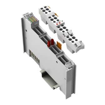
Device Description WAGO-I/O-SYSTEM 750 753-647 DALI Multi-Master View Figure 2: View Table 7: Legend for Figure “View” Pos. Description Details See Section Marking possibility with Mini- Status-LEDs “Device Description” > “Display Elements” Data contacts “Device Description” > “Connectors” CAGE CLAMP connectors “Device Description”... -
Page 25: Connectors
WAGO-I/O-SYSTEM 750 Device Description 753-647 DALI Multi-Master Connectors 3.5.1 Data Contacts/Local Bus Communication between the fieldbus coupler/controller and the I/O modules as well as the system supply of the I/O modules is carried out via the local bus. The contacting for the local bus consists of 6 data contacts, which are available as self-cleaning gold spring contacts. -
Page 26: Power Jumper Contacts/Field Supply
Device Description WAGO-I/O-SYSTEM 750 753-647 DALI Multi-Master 3.5.2 Power Jumper Contacts/Field Supply The I/O module 753-647 has no power jumper contacts. Use a power supply module! Use a power supply module for field-side power supply of downstream I/O modules. 3.5.3 CAGE CLAMP ®... - Page 27 WAGO-I/O-SYSTEM 750 Device Description 753-647 DALI Multi-Master Manual Version 1.4.3...
-
Page 28: Display Elements
Short circuit on the DALI line • Short circuit detection and signaling is only possible if the DALI line is also powered via the DALI Multi-Master Module, which is powered by a WAGO power supply. Diagnosis of the LED Statuses You can find a detailed overview of the LED statuses and their meanings in the “Diagnostics”... -
Page 29: Schematic Diagram
WAGO-I/O-SYSTEM 750 Device Description 753-647 DALI Multi-Master Schematic Diagram Figure 6: Schematic Diagram Manual Version 1.4.3... -
Page 30: Technical Data
DIN EN IEC 62386 Max. number of addressable subscribers (DALI addresses) up to HW 02 64 control gears from HW 03 63 control gears + WAGO DALI-Multi Master Transmission channel Internal bit width 24-byte data Commissioning and parameterization Via WAGO-I/O-CHECK, e!COCKPIT... -
Page 31: Connection Type
WAGO-I/O-SYSTEM 750 Device Description 753-647 DALI Multi-Master 3.9.4 Connection Type Table 13: Technical Data – Field Wiring Wire connection CAGE CLAMP ® Cross section 0.08 mm² … 2.5 mm², AWG 28 … 14 Stripped lengths 8 mm … 9 mm / 0.33 in Table 14: Technical Data –... -
Page 32: Approvals
Approvals More information about approvals. Detailed references to the approvals are listed in the document “Overview Approvals WAGO I/O SYSTEM 750”, which you can find via the internet under: www.wago.com DOWNLOADS Documentation System Description. The following approvals have been granted to 753-647 I/O modules:... -
Page 33: Standards And Guidelines
WAGO-I/O-SYSTEM 750 Device Description 753-647 DALI Multi-Master 3.11 Standards and Guidelines 753-647 I/O modules meet the following requirements on emission and immunity of interference: EMC CE-Immunity to interference EN 61000-6-2 EMC CE-Emission of interference EN 61000-6-3 EMC CE Immunity to interference and transmission provided only in... -
Page 34: Process Image
This enables the I/O module to be addressed and configured either via a dedicated IEC application, or using the WAGO DALI Configurator. If the WAGO DALI Configurator is used, the DALI Multi-Master Module is operated in the “Full mode”, as a special DALI master module is employed. The DALI master module switches the DALI Multi-Master Module to this operating mode. -
Page 35: Dedicated Iec Application
Full Mode In the “Full mode”, the 24 bytes for the process image is used (as for other complex WAGO I/O modules, such as KNX, MP bus, etc.) for tunneling of a protocol via a mailbox interface. In the “Full mode” the process image for the DALI Multi-Master Module consists of the following 24 bytes: 1 byte for Control/Status and 23 bytes for acyclic data. -
Page 36: Easy Mode
This status is stored until a new pulse results in a further status change. The WAGO DALI Configurator is used to switch to the latching relay mode. 4.4.2 Dim in 1- and 2-Button Mode A short press of the button in one-button mode switches the lighting on or off. -
Page 37: Process Image Overview In The "Easy Mode
Short Switch lighting off. Long Dim lighting (darker). The WAGO DALI Configurator is used to switch between one-button and two- button operation. 4.4.3 Process Image Overview in the “Easy Mode” Table 17: Overview of the Output Process Image in the “Easy Mode”... -
Page 38: Activating/De-Activating 64 Dali Actuators, Dimming
Process Image WAGO-I/O-SYSTEM 750 753-647 DALI Multi-Master 4.4.4 Activating/De-activating 64 DALI Actuators, Dimming Table 19: Output and Input Process Image of the DALI Multi-Master Module in “Easy Mode” – Bytes 0 and 1 DALI Output process image Byte.Bit address Input process image... -
Page 39: Table 20: Output And Input Process Image Of The Dali Multi-Master Module
WAGO-I/O-SYSTEM 750 Process Image 753-647 DALI Multi-Master Table 20: Output and Input Process Image of the DALI Multi-Master Module in “Easy Mode” – Bytes 2 … 17 Output process image Input DALI process Byte.Bit address 1-button mode 2-button mode (DA) -
Page 40: Activating/De-Activating 16 Groups, Dimming
Process Image WAGO-I/O-SYSTEM 750 753-647 DALI Multi-Master 4.4.5 Activating/De-activating 16 Groups, Dimming Table 21: Output and Input PI for the DALI Multi-Master Module in the “Easy Mode” – Byte 18 … 21 Group Output process image Input process Byte.Bit address... -
Page 41: Mounting
Always plug a bus end module (750-600) onto the end of the fieldbus node! You must always use a bus end module at all fieldbus nodes with WAGO I/O SYSTEM 750 fieldbus couplers or controllers to guarantee proper data transfer. -
Page 42: Inserting And Removing Devices
Mounting WAGO-I/O-SYSTEM 750 753-647 DALI Multi-Master Inserting and Removing Devices Do not work when devices are energized! High voltage can cause electric shock or burns. Switch off all power to the device prior to performing any installation, repair or maintenance work. -
Page 43: Removing The I/O Module
WAGO-I/O-SYSTEM 750 Mounting 753-647 DALI Multi-Master 5.2.2 Removing the I/O Module Note Remove pluggable wiring! Before removing a 753 Series I/O Module from the node, you must first remove the plug (pluggable wiring) from the I/O module (see section “Plug Removal”)! -
Page 44: Coding
Mounting WAGO-I/O-SYSTEM 750 753-647 DALI Multi-Master Figure 11: Assignment of I/O Module to Plug Using Mini-WSB Tags This plug provides an option for attaching cable binders. Figure 12: Attachment of Cable Binders 5.3.1 Coding Coding using small plastic pins and sockets facilitates mating of the I/O module with the appropriate plug. -
Page 45: Figure 14: Inserting The Coding Fingers
WAGO-I/O-SYSTEM 750 Mounting 753-647 DALI Multi-Master Figure 14: Inserting the Coding Fingers Place the plug onto the I/O module. Figure 15: Plugging the Plug into Place When the plug is removed the sockets remain in the I/O module. The coded plug can only fit in the corresponding coded I/O module (see figures below). -
Page 46: Plug Removal
Mounting WAGO-I/O-SYSTEM 750 753-647 DALI Multi-Master 5.3.2 Plug Removal Remove the plug from the I/O module by pulling the orange pull tab on the plug toward the top of the I/O module. Figure 17: Pulling the Pull Tab The plug detaches from the I/O module. -
Page 47: Connect Devices
Do not connect more than one conductor at one single connection! If more than one conductor must be routed to one connection, these must be connected in an up-circuit wiring assembly, for example using WAGO feed- through terminals. For opening the CAGE CLAMP ®... -
Page 48: Power Supply For Marine Applications
Connect Devices WAGO-I/O-SYSTEM 750 753-647 DALI Multi-Master Power Supply for Marine Applications When operating in marine applications, filter modules are to be used for the power supply! Power must be supplied via the appropriate filter module when using DALI Multi- Master Module (753-647) in marine applications. -
Page 49: Table 23: Legend For Figure "Power Supply Concept (Marine Applications) With Dc/Dc Converter (753-620) - Class A
WAGO-I/O-SYSTEM 750 Connect Devices 753-647 DALI Multi-Master Table 23: Legend for Figure “Power Supply Concept (Marine Applications) with DC/DC Converter (753-620) – Class A” Pos. Explanation Fieldbus coupler/controller Filter module 24 VDC, HI GF (750-626/020-002) or Filter module 24 VDC, HI (750-626/020-000) or... -
Page 50: Power Supply Concept (Marine Applications) With Ac/Dc Power Supply Unit - Class A
Connect Devices WAGO-I/O-SYSTEM 750 753-647 DALI Multi-Master 6.2.2 Power Supply Concept (Marine Applications) with AC/DC Power Supply Unit – Class A Figure 22: Power Supply Concept (Marine Applications) with AC/DC Power Supply Unit (787-1007) – Class A Table 24: Legend for Figure “Power Supply Concept (Marine Applications) with AC/DC Power Supply Unit (787-1007) –... -
Page 51: Power Supply Concept (Marine Applications) - Class B
WAGO-I/O-SYSTEM 750 Connect Devices 753-647 DALI Multi-Master 6.2.3 Power Supply Concept (Marine Applications) – Class B Figure 23: Power Supply Concept (Marine Applications) – Class B Table 25: Legend for Figure “Power Supply Concept (Marine Applications) – Class B” Pos. -
Page 52: Installation Notes
Module Supply Destruction of DALI subscribers due to misuse of the power supply Please note that the WAGO power supply (Item No. 787-1007) may only be connected to the DALI Multi-Master Module (753-647). Power for the DALI bus is supplied indirectly via the DALI Multi-Master Module. Connecting to the DALI bus directly can result in the destruction of connected DALI subscribers. - Page 53 (753-620) or the power supply unit for DALI Multi-Master Module (787- 1007) are suitable. The length of power supply cable between WAGO power supply (787-1007) and DALI Multi-Master Module (753-647) may be 1 m maximum. The power supply cable must also be shielded when used in marine applications.
-
Page 54: Power Supply Configuration For 753-620
Connect Devices WAGO-I/O-SYSTEM 750 753-647 DALI Multi-Master 6.3.2.1 Power Supply Configuration for 753-620 If you use a DALI Multi-Master DC/DC Converter (753-620) for power supply, exactly 1 DALI Multi-Master Module can be supplied with power. Figure 24: Configuration Diagram for the DALI Multi-Master DC/DC Converter (753-620) with 1... -
Page 55: Power Supply Configuration For 787-1007
WAGO-I/O-SYSTEM 750 Connect Devices 753-647 DALI Multi-Master 6.3.2.2 Power Supply Configuration for 787-1007 If a power supply unit (787-1007) is used, it can supply power to multiple DALI Multi-Master Modules (753-647). With total power consumption of 200 mA per DALI line, up to five DALI Multi-Master Modules (753-647) can be powered with a 787-1007 power supply unit. -
Page 56: Dali Bus Topology
Connect Devices WAGO-I/O-SYSTEM 750 753-647 DALI Multi-Master Maximum cable length 300 m! The maximum voltage drop of the DALI line should not exceed 2 V. Therefore, the maximum cable length between the more distant components is depending on the conductor cross-section limited to 300 m. -
Page 57: Dali-1 Compatibility
(ECG) has hit the market that did not comply with the timing requirements of EN 62386. While the WAGO DALI-1 module was still allowed to make allowances for timing ranges beyond the defined limits in terms of firmware, and thus could be very tolerant for communication, this is no longer permitted in accordance with the new DALI-2 standard. -
Page 58: Commissioning
DALI bus supply of a DALI Multi-Master Module. Connection of the power supply is made as explained in the installation instructions (see section “Installation Notes”). In the example given here, the fieldbus node consists of the following WAGO-I/O- SYSTEM components: Table 27: Example of a Fieldbus Node Setup... -
Page 59: Accessing The Dali Multi-Master Module
You can access the DALI Multi-Master Module (753-647) from the WAGO DALI Configurator. A communication link must be set up via the IP address of the respective WAGO PLC connected at the fieldbus node to ensure proper data exchange with the DALI Multi-Master Module via the WAGO DALI Configurator. -
Page 60: Notes On Data Management
DALI devices as an initial step and match these to the actual installation online at a later time. Offline configuration of the entire DALI network, including control gear and control units can be performed in a limited scope using the WAGO DALI Configurator. Device configurations can also be saved and restored, enabling a replaced device to be reconstructed using the values valid in the database. - Page 61 WAGO DALI Configurator! A detailed description of the software and the individual configuration steps using the WAGO DALI Configurator is given in the corresponding manual. You can download the WAGO DALI Configurator manual from the WAGO Internet site at: www.wago.com. Manual...
-
Page 62: Diagnostics
Diagnostics WAGO-I/O-SYSTEM 750 753-647 DALI Multi-Master Diagnostics Color-coded LEDs A … H provide information about different statuses in the operation of the I/O module. LED “A” Status Diagnosis LED “A” provides information about statuses of the I/O module when it is operated in “easy mode”:... -
Page 63: Led "B" Status Diagnosis
WAGO-I/O-SYSTEM 750 Diagnostics 753-647 DALI Multi-Master LED “B” Status Diagnosis Led “B” provides information about signal transmission (send): Table 29: LED “B” Status Diagnosis Status Explanation Additional Information No signal transmission No DALI signal transmission present present Green Transmission OK... -
Page 64: Led "D" Status Diagnosis
Status Explanation Additional Information 1-button mode is enabled. Only in “easy mode”; the WAGO DALI Configurator is used Green 2-button mode is enabled. to switch between 1-button and 2- button mode – see also section “Dim in 1- and 2-Button Mode.”... -
Page 65: Led "F" Status Diagnosis
LED “G” provides information about whether the power supply of the DALI line and I/O module is present and whether it is provided • via a WAGO power supply ) of the I/O (see section “I/O Module Power Supply” module or •... -
Page 66: Led "H" Status Diagnosis
A short circuit on the DALI line is only detected if the 18 V power is supplied via a WAGO power supply (item no.: 787-1007 or item no. 753-620). For this purpose, the “Enable Internal Power Supply” box must be checked (see section “Module Configuration Notes”). -
Page 67: Appendix
WAGO-I/O-SYSTEM 750 Appendix 753-647 DALI Multi-Master Appendix Device Types The following Device Types are supported by the DALI Multi-Master Module: Table 36: DALI Device Types Icon Function Icon/type Label Control Gear Standard ECG (ECG) Separate emergency lighting Discharge lamp Low voltage halogen lamp... -
Page 68: Table 37: Dali Device Types As Of Dali-2
Appendix WAGO-I/O-SYSTEM 750 753-647 DALI Multi-Master The DALI Multi-Master Module with FW 20 or higher also supports the following DALI-2 device types: Table 37: DALI Device Types as of DALI-2 Icon Function Icon/Type Label Control gear Fluorescent light (standard ECG) - Page 69 WAGO-I/O-SYSTEM 750 Appendix 753-647 DALI Multi-Master Table 37: DALI Device Types as of DALI-2 Icon Function Icon/Type Label Control gear Error message: duplicate address or (ECG) undefined response. [List of all recognized 255 Multiple device types are supported. device types]...
-
Page 70: Glossary
Appendix WAGO-I/O-SYSTEM 750 753-647 DALI Multi-Master Glossary Auto-Replace Function In the event that exactly one device is defective and is replaced by an unaddressed device, the “Replace” function automatically assigns the old short address of the previous device to the new device and subsequently restores the settings for the device using the data stored in the I/O module database. - Page 71 PLC application. Transmission within the I/O module takes place via the module-internal mailbox. Querying of process data is acyclic. “Full” mode is implemented by modules in WAGO-I/O-PRO. See also “Easy Mode.” IEC 62386 “IEC 62386” (“Digitally addressable interface for lighting”; German version DIN EN 62386: “Digital adressierbare Schnittstelle für die Beleuchtung”) is...
- Page 72 In a “multi-master,” control of the intelligent measuring and automation devices on the fieldbus is performed locally, in contrast to a master/slave system. The WAGO DALI Multi-Master Module (753-647) is a multi-master that supports the DALI interface and can utilize this interface together with other master devices.
- Page 73 WAGO-I/O-SYSTEM 750 Appendix 753-647 DALI Multi-Master because further groups are required, an additional 16 virtual groups can be created (with group addresses 17 ... 31). These groups cannot, however, be addressed via a DALI group command, but only one after the other by individual commands from the DALI Multi-Master Module (753-647).
-
Page 74: List Of Figures
List of Figures WAGO-I/O-SYSTEM 750 753-647 DALI Multi-Master List of Figures Figure 1: Overview of DALI Network with a WAGO I/O SYSTEM 750 ....21 Figure 2: View ....................24 Figure 3: Data Contacts ..................25 Figure 4: CAGE CLAMP ® Connectors ..............26 Figure 5: Display Elements.................28... -
Page 75: List Of Tables
Table 1: Revision History ..................6 Table 2: Number Notation ..................10 Table 3: Font Conventions .................10 Table 4: Required Hardware of the WAGO I/O SYSTEM ........17 Table 5: Controller Compatibility List ..............18 Table 6: Abbreviations and Terms Used in this Manual ........20 Table 7: Legend for Figure “View”... - Page 76 WAGO Kontakttechnik GmbH & Co. KG Postfach 2880 • D - 32385 Minden Hansastraße 27 • D - 32423 Minden Phone: +49 571 887 – 0 Fax: +49 571 887 – 844169 E-Mail: info@wago.com Internet: www.wago.com...
Need help?
Do you have a question about the 750 Series and is the answer not in the manual?
Questions and answers