Table of Contents
Advertisement
Quick Links
Download this manual
See also:
Manual
Pos : 2 /D okumentati on allgemein/Ei nband/Ei nband H andbuch - Dec kbl att ohne Variantenfel d (Standar d) @ 9\mod_1285229289866_0.doc x @ 64941 @ @ 1
Manual
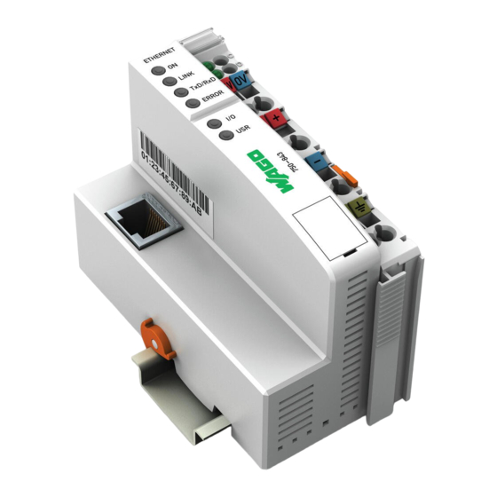
WAGO-I/O-SYSTEM 750
ETHERNET Controller 10 MBit
750-843
PLC - ETHERNET TCP/IP Programmable Fieldbus
Controller
Version 1.2.0
Pos : 3 /Alle Serien (Allgemeine M odul e)/Hinweise z ur Dokumentation/Impres sum für Standardhandbüc her - allg. Angaben, Ansc hriften, Tel efonnummer n und E-Mail-Adres sen @ 3\mod_1219151118203_21.doc x @ 21060 @ @ 1
Advertisement
Chapters
Table of Contents

Related Manuals for WAGO 750 Series


Summary of Contents for WAGO 750 Series
- Page 1 Pos : 2 /D okumentati on allgemein/Ei nband/Ei nband H andbuch - Dec kbl att ohne Variantenfel d (Standar d) @ 9\mod_1285229289866_0.doc x @ 64941 @ @ 1 Manual WAGO-I/O-SYSTEM 750 ETHERNET Controller 10 MBit 750-843 PLC - ETHERNET TCP/IP Programmable Fieldbus Controller Version 1.2.0...
- Page 2 WAGO-I/O-SYSTEM 750 750-843 ETHERNET Controller 10 MBit © 2014 by WAGO Kontakttechnik GmbH & Co. KG All rights reserved. WAGO Kontakttechnik GmbH & Co. KG Hansastraße 27 D-32423 Minden Phone: +49 (0) 571/8 87 – 0 Fax: +49 (0) 571/8 87 – 1 69 E-Mail: info@wago.com...
-
Page 3: Table Of Contents
2.1.1 Subject to Changes ................13 2.1.2 Personnel Qualifications ..............13 2.1.3 Use of the WAGO-I/O-SYSTEM 750 in Compliance with Underlying Provisions ................... 13 2.1.4 Technical Condition of Specified Devices ......... 14 Safety Advice (Precautions) ..............15 Special Use Conditions for ETHERNET Devices ........17 System Description.................. - Page 4 Overall Configuration ................57 Mounting onto Carrier Rail ..............59 5.3.1 Carrier Rail Properties ................ 59 5.3.2 WAGO DIN Rail ................60 Spacing ....................60 Mounting Sequence ................. 61 Inserting and Removing Devices ............62 5.6.1 Inserting the Fieldbus Coupler/Controller .......... 63 5.6.2...
-
Page 5: Table Of Contents
Commissioning ................... 89 Connecting Client PC and Fieldbus Nodes ..........90 Allocating the IP Address to the Fieldbus Node ........91 8.2.1 Assigning IP Address via WAGO-BOOTP-Server ......91 8.2.1.1 Note MAC ID ................92 8.2.1.2 Determining IP addresses .............. 93 8.2.1.3... - Page 6 Table of Contents WAGO-I/O-SYSTEM 750 750-843 ETHERNET Controller 10 MBit 11.1.3 Protocol layer model (Example) ............141 11.1.4 Communication Protocols ..............144 11.1.4.1 TCP (Transmission Control Protocol) ......... 144 11.1.4.2 UDP (User Datagram Protocol) ........... 144 11.1.5 Configuration and Diagnostics Protocols ......... 145 11.1.5.1...
- Page 7 WAGO-I/O-SYSTEM 750 Table of Contents 750-843 ETHERNET Controller 10 MBit 12.2.2.5 4 Channel Digital Output Modules with Diagnostics and Input Process Data ................. 189 12.2.2.6 8 Channel Digital Output Module ..........189 12.2.2.7 8 Channel Digital Output Modules with Diagnostics and Input Process Data .................
- Page 8 Table of Contents WAGO-I/O-SYSTEM 750 750-843 ETHERNET Controller 10 MBit 13.2.4 Special Conditions for Safe Use (IEC-Ex Certificate IECEx TUN 12.0039 X) ..................224 13.2.5 Special Conditions for Safe Use according to ANSI/ISA 12.12.01 . 225 List of Figures ....................226 List of Tables ......................
-
Page 9: Notes About This Documentation
Pos : 11 /Serie 750 ( WAGO-I/O-SYST EM)/Hi nweis e z ur D okumentati on/Hi nweise/Ac htung: Hinweis z ur D okumentati on Koppl er-/Ac htung: Hinweis z ur D okumentation Koppler-/C ontroll er 750-xxxx @ 4\mod_1239095964296_21.doc... -
Page 10: Symbols
Notes about this Documentation WAGO-I/O-SYSTEM 750 750-843 ETHERNET Controller 10 MBit Pos : 12.3 /All e Seri en ( Allgemei ne Module)/Ü bers chriften für alle Serien/Hinweis e z ur Dokumentation/Symbol e - Ü bersc hrift 2 @ 13\mod_1351068042408_21.doc x @ 105270 @ 2 @ 1 Symbols Pos : 12.4.1 /All e Serien ( Allgemei ne Module)/Wic htige Erläuterungen/Sicherheits- und sons tige Hinweis e/Gefahr/Gefahr: _War nung vor Personenschäden allgemei n_ - Erl äuter ung @ 13\mod_1343309450020_21.doc x @ 101029 @ @ 1... - Page 11 WAGO-I/O-SYSTEM 750 Notes about this Documentation 750-843 ETHERNET Controller 10 MBit Additional Information: Refers to additional information which is not an integral part of this documentation (e.g., the Internet). Pos : 12.5 /Dokumentation allgemei n/Glieder ungs elemente/---Seitenwechs el--- @ 3\mod_1221108045078_0.doc x @ 21810 @ @ 1 Manual Version 1.2.0...
-
Page 12: Number Notation
Notes about this Documentation WAGO-I/O-SYSTEM 750 750-843 ETHERNET Controller 10 MBit Pos : 12.6 /All e Seri en ( Allgemei ne Module)/Hi nweis e zur D okumentati on/Zahlens ysteme @ 3\mod_1221059454015_21.doc x @ 21711 @ 2 @ 1 Number Notation... -
Page 13: Important Notes
PLC programming. Pos : 15.5 /Serie 750 (WAGO-I/O-SYST EM)/Wic htige Erläuterungen/Bes timmungsgemäß e Verwendung Bes ti mmungsgemäße Verwendung 750-xxxx - Ü berschrift 3 und Inhal t @ 3\mod_1224064151234_21.doc x @ 24070 @ 3 @ 1 2.1.3... -
Page 14: Technical Condition Of Specified Devices
WAGO-I/O-SYSTEM 750 750-843 ETHERNET Controller 10 MBit Appropriate housing (per 94/9/EG) is required when operating the WAGO-I/O- SYSTEM 750 in hazardous environments. Please note that a prototype test certificate must be obtained that confirms the correct installation of the system in a housing or switch cabinet. -
Page 15: Safety Advice (Precautions)
Pos : 15.10.2 /Serie 750 ( WAGO-I/O- SYST EM)/Wic htig e Erl äuter ung en/Sic her hei ts- und s onstige Hi nweise/Gefahr/Gefahr: Ei nbau 0750- xxxx nur i n Gehäus en, Sc hränken oder el ektrisc hen Betriebsräumen! @ 6\mod_1260180556692_21.doc... - Page 16 Important Notes WAGO-I/O-SYSTEM 750 750-843 ETHERNET Controller 10 MBit Do not use any contact spray! Do not use any contact spray. The spray may impair contact area functionality in connection with contamination. Pos : 15.11.5 /Alle Serien (Allgemeine D okumente) (Allgemeine M odul e)/Wichtige Erläuter ungen/Sic herheits hinweise/Ac htung/Ac htung: Verpol ung ver mei den! @ 6\mod_1260184045744_21.doc x @ 46767 @ @ 1...
-
Page 17: Special Use Conditions For Ethernet Devices
• Do not connect control components and control networks to an open network such as the Internet or an office network. WAGO recommends putting control components and control networks behind a firewall. • Limit physical and electronic access to all automation components to authorized personnel only. -
Page 18: System Description
IEC 61131-3. Pos : 19.4 /Serie 750 (WAGO-I/O-SYST EM)/Systembesc hrei bung/Ger ät und Sys tem/Systembesc hrei bung - Kommuni kati on Kl emmenbus , LEDs , 3-Leitertec hni k @ 3\mod_1231493520906_21.doc x @ 25877 @ @ 1 I/O modules for diverse digital and analog I/O signals as well as special functions can be connected to the fieldbus coupler/controller. -
Page 19: Manufacturing Number
(if available) and further internal information for WAGO Kontakttechnik GmbH & Co. KG. Pos : 19.7 /Serie 750 (WAGO-I/O-SYST EM)/Systembesc hrei bung/Ger ät und Sys tem/Har dwar e-Adress e (M AC-ID) @ 7\mod_1270708464299_21.doc x @ 54960 @ 2 @ 1 Hardware Address (MAC ID) Each ETHERNET Controller 10 MBit has an internationally unambiguous physical address, referred to as the MAC-ID (Media Access Control Identity). -
Page 20: Component Update
The original manufacturing information on the device's housing remains unchanged. Pos : 19.10 /Serie 750 ( WAGO-I/O-SYST EM)/Systembesc hrei bung/Gerät und System/Lagerung, Kommissi onierung und Tr ansport @ 3\mod_1225446600609_21.doc x @ 24897 @ 2 @ 1 Storage, Assembly and Transport Whenever possible, the components are to be stored in their original packaging. -
Page 21: Assembly Guidelines/Standards
WAGO-I/O-SYSTEM 750 System Description 750-843 ETHERNET Controller 10 MBit Pos : 19.12 /Serie 750 ( WAGO-I/O-SYST EM)/Systembesc hrei bung/Gerät und System/Aufbaurichtli nien und N or men @ 3\mod_1231311929250_21.doc x @ 25820 @ 2 @ 1 Assembly Guidelines/Standards DIN 60204 Electrical equipping of machines... -
Page 22: Power Supply
Pos : 19.14.3 /Serie 750 ( WAGO-I/O- SYST EM)/Sys tembesc hrei bung/Vers orgung/Potenti altrennung - Bil d (Standar d + er weiterter EC O) @ 3\mod_1232950095187_21.doc x @ 26740 @ @ 1 Figure 4: Isolation for Fieldbus Couplers/Controllers (Example) Pos : 19.14.4 /D okumentati on allgemein/Gli ederungsel emente/---Seitenwec hs el--- @ 3\mod_1221108045078_0.doc x @ 21810 @ @ 1... -
Page 23: System Supply
Pos : 19.14.7 /Serie 750 ( WAGO-I/O- SYST EM)/Sys tembesc hrei bung/Vers orgung/Systemversorgung - Ans chl uss - Sys temvers orgung ( Standar d + er wei terter ECO) @ 3\mod_1232950104031_21.doc x @ 26776 @ @ 1 Figure 5: System Supply via Fieldbus Coupler/Controller (left) and via Internal System Supply Module (right) Table 3: Legend for Figure “System Supply via Fieldbus Coupler/Controller (left) and via Internal... -
Page 24: Dimensioning
Figure 6: System Voltage for Standard Couplers/Controllers and Extended ECO Couplers Pos : 19.14.10 /Seri e 750 ( WAGO-I/O-SYSTEM)/Systembes chr eibung/Versorgung/Systemvers orgung - Ansc hlus s - Hi nweis : Gl eichz. R üc ks etzen aller Vers orgungsmodul e @ 3\mod_1232950097906_21.doc x @ 26760 @ @ 1... - Page 25 Pos : 19.14.13 /Seri e 750 ( WAGO-I/O-SYSTEM)/Systembes chr eibung/Versorgung/Beis piel: @ 3\mod_1232630417843_21.doc x @ 26605 @ @ 1 Example: Pos : 19.14.14 /Seri e 750 ( WAGO-I/O-SYSTEM)/Systembes chr eibung/Versorgung/Systemvers orgung - Ausl egung - Beispi el 1 (Standar d) @ 3\mod_1232950106875_21.doc x @ 26792 @ @ 1 Calculating the current consumption on the fieldbus coupler:...
- Page 26 (87 % Efficiency of the power supply at nominal load 24 V) Pos : 19.14.20 /Seri e 750 ( WAGO-I/O-SYSTEM)/Systembes chr eibung/Versorgung/Systemvers orgung - Ausl egung - Hi nweis: Bei Test der Str omaufnahme Ausg äng e akti vi eren @ 3\mod_1232950110750_21.doc x @ 26812 @ @ 1...
-
Page 27: Field Supply
Potential distribution to adjacent I/O modules Pos : 19.14.28 /Seri e 750 ( WAGO-I/O-SYSTEM)/Systembes chr eibung/Versorgung/F eldversorgung - Ans chl uss - Weiterl eitung Vers orgungsspg., Strombel astung 10 A, neue Eins peisekl emme @ 8\mod_1279805441785_21.doc x @ 60845 @ @ 1 The field-side power supply is automatically derived from the power jumper contacts when snapping an I/O module. - Page 28 Pos : 19.14.29 /Seri e 750 ( WAGO-I/O-SYSTEM)/Systembes chr eibung/Versorgung/F eldversorgung - Ans chl uss - 2 Hi nweise: Potential neu ei ns peis en + Dis tanz kl emme @ 3\mod_1232950091343_21.doc x @ 26724 @ @ 1...
-
Page 29: Fusing
WAGO-I/O-SYSTEM 750 System Description 750-843 ETHERNET Controller 10 MBit Pos : 19.14.31 /Seri e 750 ( WAGO-I/O-SYSTEM)/Systembes chr eibung/Versorgung/F eldversorgung - Absic herung @ 3\mod_1232950081500_21.doc x @ 26692 @ 4 @ 1 3.6.3.2 Fusing Internal fusing of the field supply is possible for various field voltages via an appropriate power supply module. - Page 30 System Description WAGO-I/O-SYSTEM 750 750-843 ETHERNET Controller 10 MBit Figure 9: Removing the Fuse Carrier Lifting the cover to the side opens the fuse carrier. Figure 10: Opening the Fuse Carrier Figure 11: Changing the Fuse After changing the fuse, the fuse carrier is pushed back into its original position.
- Page 31 WAGO-I/O-SYSTEM 750 System Description 750-843 ETHERNET Controller 10 MBit Alternatively, fusing can be done externally. The fuse modules of the WAGO series 281 and 282 are suitable for this purpose. Figure 12: Fuse Modules for Automotive Fuses, Series 282 Figure 13: Fuse Modules for Automotive Fuses, Series 2006...
-
Page 32: Supplementary Power Supply Regulations
System Description WAGO-I/O-SYSTEM 750 750-843 ETHERNET Controller 10 MBit Pos : 19.14.33 /Seri e 750 ( WAGO-I/O-SYSTEM)/Systembes chr eibung/Versorgung/Ergänz ende Eins peisungs vors chriften (Standar d) @ 3\mod_1232950080218_21.doc x @ 26684 @ 3 @ 1 3.6.4 Supplementary Power Supply Regulations The WAGO-I/O-SYSTEM 750 can also be used in shipbuilding or offshore and onshore areas of work (e. -
Page 33: Supply Example
Figure 17: Supply Example for Standard Couplers/Controllers Pos : 19.14.37 /Seri e 750 ( WAGO-I/O-SYSTEM)/Systembes chr eibung/Versorgung/Vers orgungs beis piel - Legende zu Abbil dung "Vers orgungs beis pi el für F eldbus koppler/-c ontroller" @ 16\mod_1375881755097_21.doc x @ 128220 @ @ 1 Manual Version 1.2.0... - Page 34 System Description WAGO-I/O-SYSTEM 750 750-843 ETHERNET Controller 10 MBit Table 8: Legend for Figure “Supply Example for Fieldbus Coupler/Controller” Pos. Description Power Supply on coupler via external Supply Module Power Supply with optional ground Internal System Supply Module Separation module recommended...
-
Page 35: Power Supply Unit
WAGO-I/O-SYSTEM 750 System Description 750-843 ETHERNET Controller 10 MBit Pos : 19.14.39 /Seri e 750 ( WAGO-I/O-SYSTEM)/Systembes chr eibung/Versorgung/Netzger äte @ 3\mod_1232950093484_21.doc x @ 26728 @ 3 @ 1 3.6.6 Power Supply Unit The WAGO-I/O-SYSTEM 750 requires a 24 VDC voltage (system supply). -
Page 36: Grounding
System Description WAGO-I/O-SYSTEM 750 750-843 ETHERNET Controller 10 MBit Pos : 19.14.41 /Seri e 750 ( WAGO-I/O-SYSTEM)/Systembes chr eibung/Versorgung/Er dung @ 3\mod_1231246555687_21.doc x @ 25802 @ 23443 @ 1 Grounding 3.7.1 Grounding the DIN Rail 3.7.1.1 Framework Assembly When setting up the framework, the carrier rail must be screwed together with the electrically conducting cabinet or housing frame. -
Page 37: Grounding Function
WAGO-I/O-SYSTEM 750 System Description 750-843 ETHERNET Controller 10 MBit 3.7.2 Grounding Function The grounding function increases the resistance against electro-magnetic interferences. Some components in the I/O system have a carrier rail contact that dissipates electro-magnetic interferences to the carrier rail. -
Page 38: Shielding
System Description WAGO-I/O-SYSTEM 750 750-843 ETHERNET Controller 10 MBit Pos : 19.14.43 /Seri e 750 ( WAGO-I/O-SYSTEM)/Systembes chr eibung/Versorgung/Schir mung @ 3\mod_1231251994828_21.doc x @ 25813 @ 23333 @ 1 Shielding 3.8.1 General Use of shielded cables reduces electromagnetic interference and thus increases signal quality. -
Page 39: Signal Lines
3.8.4 WAGO Shield Connecting System The WAGO shield connecting system consists of shield clamping saddles, busbars and various mounting carriers. These components can be used to achieve many different configurations. -
Page 40: Device Description
Pos : 22.12 /Serie 750 ( WAGO-I/O-SYST EM)/Gerätebeschr eibung/Ei nleitung/Fel dbus koppl er/-contr oller/Einl eitender T ext/D er Pr ozessdatenaustausc h fi ndet mit Hilfe des MOD BUS/TCP (UDP)-Pr otokolls statt. (342,842) @ 6\mod_1255505900078_21.doc x @ 42735 @ @ 1... -
Page 41: Table 1: Compatibility
Pos : 22.15 /Serie 750 ( WAGO-I/O-SYST EM)/Gerätebeschr eibung/Ei nleitung/Fel dbus koppl er/-contr oller/Einl eitender T ext/F ür di e Konfigur ati on und Ver wal tung des Sys tems bi etet (829,830,841,842,849,871,872,873,881,882) @ 6\mod_1255511017906_21.doc... -
Page 42: View
View Pos : 26.1 /Serie 750 (WAGO-I/O-SYST EM)/Ger ätebesc hrei bung/Ansic ht/Fel dbus koppl er/-contr oller/Leg ende/Ansic ht - allg. Einl eitung für Koppler/C ontroll er @ 4\mod_1238494230133_21.doc x @ 29446 @ @ 1 The view below shows the three parts of the device: •... -
Page 43: Table 1: Legend To The View Ethernet Tcp/Ip Fieldbus Controller
Pos : 26.4 /Serie 750 (WAGO-I/O-SYST EM)/Ger ätebesc hrei bung/Ansic ht/Fel dbus koppl er/-contr oller/Leg ende/Ansic ht - Legende zur Ansicht ETHERN ET TC P/IP-Contr oller ( 750-842, - 843) - T abellenkopf und Nr: 1 @ 5\mod_1244116110427_21.doc... -
Page 44: Connectors
Connectors Pos : 29 /Serie 750 ( WAGO-I/O-SYST EM)/Ger ätebesc hrei bung/Schematisc he Sc haltbil der/Fel dbus koppl er/-contr oller/Ger äteei nspeis ung - Ü berschrift 3 und Einl eitung 750-0xxx @ 5\mod_1245074097866_21.doc x @ 35349 @ 3 @ 1 4.2.1... -
Page 45: Table 1: Rj-45 Connector And Rj-45 Connector Configuration
WAGO-I/O-SYSTEM 750 Device Description 750-843 ETHERNET Controller 10 MBit Table 13: RJ-45 Connector and RJ-45 Connector Configuration Contact Signal TD + Transmit + TD - Transmit - RD + Receive + free free RD - Receive - free free Pos : 31.6 /All e Seri en ( Allgemei ne Dokumente) ( Allgemei ne Module)/Wic htige Erläuterungen/Sicherheits hi nweis e/Ac htung/Achtung: Nic ht in T el ekommuni kationsnetzen eins etzen! (Zus atz RJ-45) @ 3\mod_1224065187468_21.doc x @ 24076 @ @ 1 Do not use in telecommunication circuits! Only use devices equipped with ETHERNET or RJ-45 connectors in LANs. -
Page 46: Display Elements
Pos : 34.6 /Serie 750 (WAGO-I/O-SYST EM)/Ger ätebesc hrei bung/Anz eigeelemente/Fel dbus koppl er/-contr oller/Legende/Anz eigeelemente - F eldbus status ETHERN ET-basi ert, spezifisc her Tabellenteil 'TxD /R xD' @ 4\mod_1240920760083_21.doc x @ 31791 @ @ 1... - Page 47 WAGO-I/O-SYSTEM 750 Device Description 750-843 ETHERNET Controller 10 MBit More information about the LED Signaling Read the detailed description for the evaluation of the displayed LED state in the section “Diagnostics” > … > “LED Signaling”. Pos : 35 /D okumentation allgemei n/Glieder ungs elemente/---Seitenwechs el--- @ 3\mod_1221108045078_0.doc x @ 21810 @ @ 1 Manual Version 1.2.0...
-
Page 48: Operating Elements
Pos : 37.1 /Serie 750 (WAGO-I/O-SYST EM)/Ger ätebesc hrei bung/Bedienel emente/F el dbus koppl er/-contr oller/Ser vic e-Sc hnitts tell e - Ü bersc hrift 3, und allgemei ne Ei nleitung @ 4\mod_1239105167430_21.doc x @ 30221 @ 3 @ 1... -
Page 49: Table 1: Legend For Figure „Mode Selector Switch
Pos : 38.2 /Serie 750 (WAGO-I/O-SYST EM)/Ger ätebesc hrei bung/Bedienel emente/F el dbus koppl er/-contr oller/Hi nweis : Vorpr ogrammier en der Ausg äng e für Pr ogrammstopp! (Betriebs artens chalter ohne WBM) @ 4\mod_1240571705443_21.doc... - Page 50 Device Description WAGO-I/O-SYSTEM 750 750-843 ETHERNET Controller 10 MBit Table 2: Mode Selector Switch Positions, Dynamic Positions During Ongoing Operation Position change for the Function mode selector switch From the top to the “STOP” – stop program processing, center position...
-
Page 51: Technical Data
Pos : 41.1 /Serie 750 (WAGO-I/O-SYST EM)/Ger ätebesc hrei bung/T echnisc he Daten/F el dbus koppl er/-contr oller/T ec hnisc he D aten 750- 0842, - 0843 - T eil 1 @ 8\mod_1280476729754_21.doc x @ 61664 @ 33 @ 1... -
Page 52: Supply
Pos : 41.5 /Serie 750 (WAGO-I/O-SYST EM)/Ger ätebesc hrei bung/T echnisc he Daten/Kli mati sche U mweltbeding ung enT ec hnis che D aten Kli mat. Umweltbed. ohne er w. Temp. 0...55°C/- 25...+ 85°C @ 5\mod_1247657968368_21.doc... -
Page 53: Climatic Environmental Conditions
– dust, caustic vapors or gases – ionizing radiation Pos : 41.6 /Serie 750 (WAGO-I/O-SYST EM)/Ger ätebesc hrei bung/T echnisc he Daten/Sons tige/M echanisc he Belas tbar keit (Standar d) @ 3\mod_1232967663359_21.doc x @ 26972 @ 3 @ 1 4.5.8 Mechanical Strength acc. -
Page 54: Approvals
Pos : 50 /Serie 750 ( WAGO-I/O-SYST EM)/Ger ätebesc hrei bung/Z ulass ungen/Schiff/Z ulas sungen F Bkoppler/Zul ass ung en FBkoppl er/-contr oller 750- xxxx Schiff, ohne Vari antenangabe - Einl eitung @ 5\mod_1245241344146_21.doc x @ 35501 @ @ 1... - Page 55 WAGO-I/O-SYSTEM 750 Device Description 750-843 ETHERNET Controller 10 MBit BV (Bureau Veritas) Pos : 51.4 /All e Seri en ( Allgemei ne Dokumente) ( Allgemei ne Module)/Z ulassungen/Sc hiffsz ul ass ungen/DN V (D et N ors ke Veritas) Cl ass B @ 3\mod_1224492540562_0.doc x @ 24224 @ @ 1...
-
Page 56: Standards And Guidelines
Pos : 54 /Serie 750 ( WAGO-I/O-SYST EM)/Ger ätebesc hrei bung/N ormen und Ric htlini en/EM V-Nor men FBkoppl er/EM V-Nor men FBkoppl er/-c ontroller 750- xxxx, ohne Vari antenangabe - Einl eitung @ 5\mod_1245244309850_21.doc... -
Page 57: Mounting
Pos : 59 /All e Seri en (Allgemei ne Module)/Ü berschriften für alle Serien/Monti eren/M ontier en - Übersc hrift 1 @ 3\mod_1225446744750_21.doc x @ 24900 @ 1 @ 1 Mounting Pos : 60.1 /Serie 750 (WAGO-I/O-SYST EM)/M ontieren/D emontieren/Einbaul age @ 3\mod_1225446818312_21.doc x @ 24903 @ 2 @ 1 Installation Position Along with horizontal and vertical installation, all other installation positions are allowed. - Page 58 Mounting WAGO-I/O-SYSTEM 750 750-843 ETHERNET Controller 10 MBit Increase the total length using a coupler module for internal data bus extension! You can increase the total length of a fieldbus node by using a 750-628 I/O Module (coupler module for internal data bus extension). For such a configuration, attach a 750-627 I/O Module (end module for internal data bus extension) after the last I/O module of a module assembly.
-
Page 59: Mounting Onto Carrier Rail
WAGO-I/O-SYSTEM 750 Mounting 750-843 ETHERNET Controller 10 MBit Pos : 60.4 /Serie 750 (WAGO-I/O-SYST EM)/M ontieren/D emontieren/M ontage auf Tr agschi ene @ 3\mod_1225447227234_21.doc x @ 24906 @ 233 @ 1 Mounting onto Carrier Rail 5.3.1 Carrier Rail Properties All system components can be snapped directly onto a carrier rail in accordance with the European standard EN 50022 (DIN 35). -
Page 60: Wago Din Rail
210-196 35 x 7.5; 1 mm; aluminum; unslotted Pos : 60.5 /Serie 750 (WAGO-I/O-SYST EM)/M ontieren/D emontieren/Abstände @ 3\mod_1225448283750_21.doc x @ 24920 @ 2 @ 1 Spacing The spacing between adjacent components, cable conduits, casing and frame sides must be maintained for the complete fieldbus node. -
Page 61: Mounting Sequence
Pos : 60.10 /Serie 750 ( WAGO-I/O-SYST EM)/Wichtig e Erl äuter ung en/Sic her hei ts- und s onstige Hinweise/Hinweis/Hi nweis : Bus absc hluss nic ht vergessen! @ 6\mod_1256194225557_21.doc x @ 43432 @ @ 1 Don't forget the bus end module! -
Page 62: Inserting And Removing Devices
WAGO-I/O-SYSTEM 750 750-843 ETHERNET Controller 10 MBit Pos : 60.12 /Serie 750 ( WAGO-I/O-SYST EM)/Monti eren/D emonti eren/Ger äte ei nfügen und entfernen - Ü bersc hrift 2 @ 3\mod_1231768483250_21.doc x @ 25950 @ 2 @ 1 Inserting and Removing Devices Pos : 60.13 /Alle Serien (Allgemeine M odul e)/Wichtige Erläuterungen/Sic herheits- und s onstige Hinweise/Achtung/Ac htung: Ar beiten an Geräten nur spannungsfrei durchführen! @ 6\mod_1256193963573_21.doc x @ 43426 @ @ 1... -
Page 63: Inserting The Fieldbus Coupler/Controller
WAGO-I/O-SYSTEM 750 Mounting 750-843 ETHERNET Controller 10 MBit Pos : 60.15 /Serie 750 ( WAGO-I/O-SYST EM)/Monti eren/D emonti eren/F eldbus koppler/-c ontroll er ei nfügen @ 3\mod_1234168173031_21.doc x @ 27456 @ 3 @ 1 5.6.1 Inserting the Fieldbus Coupler/Controller When replacing the fieldbus coupler/controller for an already available fieldbus coupler/controller, position the new fieldbus coupler/controller so that the tongue and groove joints to the subsequent I/O module are engaged. -
Page 64: Inserting The I/O Module
Mounting WAGO-I/O-SYSTEM 750 750-843 ETHERNET Controller 10 MBit Pos : 60.19 /Serie 750 ( WAGO-I/O-SYST EM)/Monti eren/D emonti eren/Bus kl emme einfügen @ 3\mod_1231769726703_21.doc x @ 25989 @ 3 @ 1 5.6.3 Inserting the I/O Module Position the I/O module so that the tongue and groove joints to the fieldbus coupler/controller or to the previous or possibly subsequent I/O module are engaged. -
Page 65: Removing The I/O Module
WAGO-I/O-SYSTEM 750 Mounting 750-843 ETHERNET Controller 10 MBit Pos : 60.21 /Serie 750 ( WAGO-I/O-SYST EM)/Monti eren/D emonti eren/Bus kl emme entfer nen @ 4\mod_1239169375203_21.doc x @ 30334 @ 3 @ 1 5.6.4 Removing the I/O Module Remove the I/O module from the assembly by pulling the release tab. -
Page 66: Connect Devices
Pos : 63.4 /Serie 750 (WAGO-I/O-SYST EM)/Wic htige Erläuterungen/Sicherheits- und sonstig e Hinweis e/Achtung/Achtung: ESD - Auf g ute Erdung der U mgebung ac hten! @ 7\mod_1266318538667_21.doc x @ 50708 @ @ 1 Ensure that the environment is well grounded! The devices are equipped with electronic components that may be destroyed by electrostatic discharge. -
Page 67: Power Contacts/Field Supply
Figure 33: Example for the Arrangement of Power Contacts Pos : 63.9 /Serie 750 (WAGO-I/O-SYST EM)/Wic htige Erläuterungen/Sicherheits- und sonstig e Hinweis e/Hinweis/Hi nweis: F eldbus knoten mit s mar tDESIGN ER konfiguri eren und überpr üfen @ 6\mod_1256193439792_21.doc x @ 43420 @ @ 1 Field bus node configuration and test via smartDESIGNER ®... -
Page 68: Connecting A Conductor To The Cage Clamp
WAGO-I/O-SYSTEM 750 750-843 ETHERNET Controller 10 MBit Pos : 63.11 /Serie 750 ( WAGO-I/O-SYST EM)/Ansc hließ en/Leiter an CAGE CLAMP ansc hließ en (allgemein) - Ü berschrift 2 und T ext @ 3\mod_1225448660171_21.doc x @ 24928 @ 2 @ 1 ®... -
Page 69: Function Description
Run-up Pos : 67.2 /Serie 750 (WAGO-I/O-SYST EM)/F unktions beschr eibung/Betriebss ystem/Hinweis: Betriebs artens chalter darf sich nic ht i n der unteren Stellung befi nden! @ 17\mod_1383727204961_21.doc x @ 136741 @ @ 1 The mode selector switch may not be located in the lower position! The mode selector switch may not be set at the bottom position during run- Pos : 67.3 /Serie 750 (WAGO-I/O-SYST EM)/F unktions beschr eibung/Betriebss ystem/Betri ebs s ystem C ontroller - Anfangs text (Anlauf des Fel dbusc ontroll ers) @ 4\mod_1239104024406_21.doc x @ 30218 @ @ 1... - Page 70 Pos : 69 /Serie 750 ( WAGO-I/O-SYST EM)/F unktions beschr eibung/Betriebss ystem/Betri ebs s ystem C ontroller - Diagramm ( 16- Bit, ohne Files ys tem) @ 9\mod_1283251093091_21.doc x @ 64399 @ @ 1 Figure 35: Run-up of the Fieldbus Controller Pos : 70 /D okumentation allgemei n/Glieder ungs elemente/---Seitenwechs el--- @ 3\mod_1221108045078_0.doc x @ 21810 @ @ 1...
-
Page 71: Process Data Architecture
Pos : 72.5 /Serie 750 (WAGO-I/O-SYST EM)/F unktions beschr eibung/Prozes sabbild/F ür das lokal e Pr oz ess abbild, Daten abhängig von der R eihenfolg e ihr er Positi on (Contr oller) @ 6\mod_1256034703953_21.doc x @ 43158 @ @ 1... - Page 72 Pos : 72.9 /Serie 750 (WAGO-I/O-SYST EM)/F unktions beschr eibung/Prozes sabbild/Bei all en WAGO-Fel dbusc ontroll ern i st der Zugriff der SPS auf di e Proz ess daten unabhängig von ... @ 6\mod_1256038962984_21.doc x @ 43173 @ @ 1...
-
Page 73: Example Of An Input Process Image
750-843 ETHERNET Controller 10 MBit Pos : 72.14 /Serie 750 ( WAGO-I/O-SYST EM)/Funkti onsbesc hrei bung/Proz ess abbild/Beis piel für ein Ei ngangspr ozessabbild- Beis piel für ei n Ausg angs proz ess abbil d @ 6\mod_1256040947968_21.doc x @ 43188 @ 33 @ 1 7.2.2... -
Page 74: Example Of An Output Data Process Image
Figure 37: Example of Process Image for Output Data Pos : 72.15 /Serie 750 ( WAGO-I/O-SYST EM)/Funkti onsbesc hrei bung/Proz ess abbild/Pr oz ess daten M ODBU S/TC P - Ü bersc hrift 3 @ 9\mod_1281511494153_21.doc x @ 63020 @ 3 @ 1 Manual Version 1.2.0... -
Page 75: Process Data Modbus/Tcp
Intel formats. Pos : 72.18 /Serie 750 ( WAGO-I/O-SYST EM)/Funkti onsbesc hrei bung/Proz ess abbild/Informati on: Weiter e Infos zu dem fel dbuss pezifisc hen Proz ess datenaufbau für MOD BU S @ 9\mod_1281511861020_21.doc x @ 63028 @ @ 1... -
Page 76: Data Exchange
Pos : 75.7 /Serie 750 (WAGO-I/O-SYST EM)/F unktions beschr eibung/Datenaus tausc h/D atenaustaus ch - Der Zugriff des F eldbusc ontrollers auf di e D aten erfolgt mit Hilfe eines IEC- 611... @ 6\mod_1256044879953_21.doc x @ 43228 @ @ 1... -
Page 77: Memory Areas
Figure 38: Memory Areas and Data Exchange Pos : 75.9 /Serie 750 (WAGO-I/O-SYST EM)/F unktions beschr eibung/Datenaus tausc h/Speic her ber eiche - Legende " Speic her ber eiche und D atenaustausc h" (750-842, -843, 833) @ 8\mod_1281011331911_21.doc x @ 62435 @ @ 1 In the memory space word 0 ... - Page 78 0x0200 or 0x1000 to the MODBUS address. Pos : 75.12 /Serie 750 ( WAGO-I/O-SYST EM)/Funkti onsbesc hrei bung/D atenaustausch/Speicherbereic he MOD BUS/Speicherbereic he MOD BU S - Er kl ärung D atens peicher, Progrspeic her, Remanent (750- 843) @ 8\mod_1281012393074_21.doc x @ 62449 @ @ 1...
- Page 79 Function Description 750-843 ETHERNET Controller 10 MBit This breakdown can be varied (see following explanation). NOVRAM memory allocation can be changed in WAGO-I/O-PRO CAA! The breakdown of the NOVRAM can be modified when required in the programming software WAGO-I/O-PRO CAA/Register "Resources"/Dialog window "Target system settings".
-
Page 80: Addressing
Addressing Pos : 75.15 /Serie 750 ( WAGO-I/O-SYST EM)/Funkti onsbesc hrei bung/D atenaustausch/Adres sier ung/Adr essi erung - Ei nleitung (Controll er) @ 6\mod_1256047921109_21.doc x @ 43260 @ @ 1 Module inputs and outputs in a controller are addressed internally as soon as they are started. -
Page 81: Addressing Of I/O Modules
Function Description 750-843 ETHERNET Controller 10 MBit Pos : 75.17 /Serie 750 ( WAGO-I/O-SYST EM)/Funkti onsbesc hrei bung/D atenaustausch/Adres sier ung/Adr essi erung - Adres sierung der Bus klemmen @ 7\mod_1265981710444_21.doc x @ 50597 @ 4 @ 1 7.3.2.1 Addressing of I/O Modules... -
Page 82: Iec-61131-3 Address Areas
IEC-61131-3 Address Areas Pos : 75.20 /Serie 750 ( WAGO-I/O-SYST EM)/Funkti onsbesc hrei bung/D atenaustausch/Adres sier ung/Adr essi erung - IEC-Adr essr äume i m Ü berblic k ( 750-842, - 843) @ 8\mod_1281014846317_21.doc x @ 62489 @ @ 1... -
Page 83: Table 1: Addressing Example
The character strings for absolute addresses must be entered connected, i.e. without spaces or special characters! Pos : 75.22 /Serie 750 ( WAGO-I/O-SYST EM)/Funkti onsbesc hrei bung/D atenaustausch/Adres sier ung/Adr essi erung - Beispi eladressier ung @ 6\mod_1256049728484_21.doc x @ 43307 @ @ 1 Addressing example:... -
Page 84: Data Exchange Between Modbus/Tcp Master And I/O Modules
750-843 ETHERNET Controller 10 MBit Pos : 75.24 /Serie 750 ( WAGO-I/O-SYST EM)/Funkti onsbesc hrei bung/D atenaustausch/Datenaus tausc h - D atenaustausc h MOD BUS/TCP-M aster und Bus klemmen (750- 842, -843) @ 8\mod_1281016450113_21.doc x @ 62497 @ 3 @ 1 7.3.3... -
Page 85: Data Exchange Between Plc Function (Cpu) And I/O Modules
"MODBUS Register Mapping". Pos : 75.25 /Serie 750 ( WAGO-I/O-SYST EM)/Funkti onsbesc hrei bung/D atenaustausch/Datenaus tausc h - D atenaustausc h SPS-Funkti onalität (C PU) und Bus kl emmen ( 750-842, - 843) @ 8\mod_1281016210965_21.doc x @ 62493 @ 3 @ 1 7.3.4... -
Page 86: Data Exchange Between Master And Plc Function (Cpu)
Figure 42: Data exchange between MODBUS master and PLC functionality Pos : 75.27 /Serie 750 ( WAGO-I/O-SYST EM)/Funkti onsbesc hrei bung/D atenaustausch/Datenaus tausc h - Beispi el MOD BUS/TCP-M aster und SPS-Funkti onalität (CPU) @ 6\mod_1256050019140_21.doc x @ 43319 @ 4 @ 1 7.3.5.1... -
Page 87: Common Access Of Modbus/Tcp Master And Plc Functionality To Outputs
Pos : 75.28 /Serie 750 ( WAGO-I/O-SYST EM)/Funkti onsbesc hrei bung/D atenaustausch/Datenaus tausc h - Gemei nsamer Z ugriff PFC und M ODBU S/TC P-Mas ter auf Ausg äng e (750-842, -843) @ 8\mod_1281017604374_21.doc... -
Page 88: Application Example
Pos : 75.29 /Serie 750 ( WAGO-I/O-SYST EM)/Funkti onsbesc hrei bung/D atenaustausch/Datenaus tausc h - Anwendungsbeispi el, Adressi erungsbeis piel für einen F eldbus knoten @ 6\mod_1255937031906_21.doc x @ 43042 @ 3 @ 1 7.3.7... -
Page 89: Commissioning
Pos : 78.3 /Serie 750 (WAGO-I/O-SYST EM)/In Betrieb nehmen/Fel dbus knoten i n Betrieb nehmen/Einl eitung - Hi nweis: Exempl arisches Beispi el, 3 erfor derliche Ar bei tssc hritte (Koppl er/Contr oller) @ 4\mod_1238672477625_21.doc... -
Page 90: Connecting Client Pc And Fieldbus Nodes
Pos : 78.9 /Serie 750 (WAGO-I/O-SYST EM)/In Betrieb nehmen/Fel dbus knoten i n Betrieb nehmen/H oc hlauf und LEDs - Fehler 6- 4: noch kei ne IP-Adress e zugewi es en @ 4\mod_1243590721843_21.doc x @ 34504 @ @ 1 If an error has occurred during startup, a fault code is flashed by the I/O LED. -
Page 91: Allocating The Ip Address To The Fieldbus Node
Pos : 78.15.2 /Serie 750 ( WAGO-I/O- SYST EM)/In Betri eb nehmen/F eldbus knoten in Betri eb nehmen/Hinweis: BootP muss i n WAGO- Ether net- Setti ngs standardmäßig akti viert sei n! @ 9\mod_1281681037977_21.doc x @ 63549 @ @ 1... -
Page 92: Note Mac Id
Pos : 78.15.13 /Seri e 750 ( WAGO-I/O-SYSTEM)/In Betrieb nehmen/Fel dbus knoten in Betrieb nehmen/Hoc hl auf und LEDs - F ehl er allgemein, Hi nweis : Sig nalisi erung/Blinkcode-Aus w. @ 4\mod_1243594306433_21.doc x @ 34538 @ @ 1 If an error occurs during start-up indicated by the I/O LED flashing red, evaluate the error code and argument and resolve the error. -
Page 93: Determining Ip Addresses
“Diagnostics” > … > “LED Signaling”. Pos : 78.15.14 /Seri e 750 ( WAGO-I/O-SYSTEM)/In Betrieb nehmen/Fel dbus knoten in Betrieb nehmen/Hoc hl auf und LEDs - F ehl er: keine IP (C ontroll er) @ 6\mod_1264498406795_21.doc x @ 48704 @ @ 1 Error codes and error arguments are indicated by the frequency of a LED flash sequence. -
Page 94: Editing Bootp Table
_ _ _ . _ _ _ . _ _ _ . _ _ _ Pos : 78.15.17 /Seri e 750 ( WAGO-I/O-SYSTEM)/In Betrieb nehmen/Fel dbus knoten in Betrieb nehmen/BootP-T abelle editi eren - T eil 1 @ 6\mod_1264490053141_21.doc x @ 48675 @ 4 @ 1 8.2.1.3... -
Page 95: Table 1: Information In The Bootp Table
750-843 ETHERNET Controller 10 MBit Pos : 78.15.18 /Seri e 750 ( WAGO-I/O-SYSTEM)/In Betrieb nehmen/Fel dbus knoten in Betrieb nehmen/BootP-T abelle editi eren - T eil 2 (Contr oller) @ 6\mod_1264498719375_21.doc x @ 48711 @ @ 1 The examples shown contain the following information:... -
Page 96: Activating Bootp
750-843 ETHERNET Controller 10 MBit Close the editor. Pos : 78.15.19 /Seri e 750 ( WAGO-I/O-SYSTEM)/In Betrieb nehmen/Fel dbus knoten in Betrieb nehmen/BootP akti vier en - Teil 1 ( WAGO-BootP) @ 4\mod_1239097776437_21.doc x @ 30138 @ 4 @ 1 8.2.1.4... -
Page 97: Disabling Bootp
Disabling BootP Pos : 78.15.24 /Seri e 750 ( WAGO-I/O-SYSTEM)/In Betrieb nehmen/Fel dbus knoten in Betrieb nehmen/Bei akti vi ertem BootP- Protokoll er wartet der Contr oller die permanente Anwes enheit (C ontroller) @ 4\mod_1239104652546_21.doc x @ 30193 @ @ 1 When the BootP protocol is activated the controller expects the BootP server to be permanently available. - Page 98 Select the Network tab. Pos : 78.15.36 /Seri e 750 ( WAGO-I/O-SYSTEM)/In Betrieb nehmen/Fel dbus knoten in Betrieb nehmen/IP- Adr ess e mit ETH ERNET- Setti ngs verg eben, Schritt 7 "Statisc he Adress e" @ 20\mod_1410439747452_21.doc x @ 163218 @ @ 1 To assign a permanent address, select the option "Use the following...
-
Page 99: Reasons For Failed Ip Address Assignment
750-843 ETHERNET Controller 10 MBit Pos : 78.15.40 /Seri e 750 ( WAGO-I/O-SYSTEM)/In Betrieb nehmen/Fel dbus knoten in Betrieb nehmen/Gründe für ei ne fehlg esc hlagene IP-Adress vergabe (bei BootP) (Contr oller) @ 4\mod_1239098186078_21.doc x @ 30141 @ 4 @ 1 8.2.1.6... -
Page 100: Testing The Function Of The Fieldbus Node
Pos : 78.17.4 /Serie 750 ( WAGO-I/O- SYST EM)/In Betri eb nehmen/F eldbus knoten in Betri eb nehmen/H ochl auf und LEDs - F ehler allgemei n, Hi nweis: Signalisierung/Bli nkc ode-Aus w. @ 4\mod_1243594306433_21.doc... -
Page 101: Restoring Factory Settings
Pos : 78.19.5 /Serie 750 ( WAGO-I/O- SYST EM)/In Betri eb nehmen/F eldbus knoten in Betri eb nehmen/Wer ksei nstellungen wi ederherstellen - ETHERN ET-Settings s tarten,D efault,Conti nue, Neust Schritte 4-5 @ 5\mod_1244645750981_21.doc x @ 35277 @ @ 1... -
Page 102: Programming The Pfc Using Wago-I/O-Pro
750-843 ETHERNET Controller 10 MBit Pos : 80.1 /Serie 750 (WAGO-I/O-SYST EM)/In Betrieb nehmen/In WAGO-I/O-PR O programmi eren/PFC mit WAGO-I/O-PRO pr ogrammier en - Übersc hrift 1, mit Bes chr eibung T eil 1 @ 4\mod_1240896463296_21.doc x @ 31480 @ 1 @ 1... - Page 103 FUP, AS, ST or CFC). Pos : 80.5 /Serie 750 (WAGO-I/O-SYST EM)/In Betrieb nehmen/In WAGO-I/O-PR O programmi eren/Bus kl emmenkonfiguration z us ammenz ustellen (KEIN E „ EA-c onfig.xml“) @ 9\mod_1282201298857_21.doc x @ 63990 @ @ 1 To ensure that you can access all I/O module data properly in your new project, first compile the I/O module configuration based on the existing fieldbus node hardware.
-
Page 104: Configuring The Fieldbus Controller Using The I/O Configurator
750-843 ETHERNET Controller 10 MBit Pos : 80.7 /Serie 750 (WAGO-I/O-SYST EM)/In Betrieb nehmen/In WAGO-I/O-PR O programmi eren/F eldbuscontr oller mit dem I/O- Konfigur ator konfigurieren @ 4\mod_1240907399109_21.doc x @ 31617 @ 2 @ 1 Configuring the Fieldbus Controller using the I/O... - Page 105 Pos : 80.8 /Serie 750 (WAGO-I/O-SYST EM)/In Betrieb nehmen/In WAGO-I/O-PR O programmi eren/Ü bers etz en Si e das Projekt i m M enü Proj ekt mit Ü bers etzen/Alles übers etz en @ 9\mod_1282202346611_21.doc...
-
Page 106: Ethernet Libraries For Wago-I/O-Pro
I/O-PRO. Pos : 80.12 /Serie 750 ( WAGO-I/O-SYST EM)/In Betri eb nehmen/In WAGO-I/O-PRO pr ogrammier en/ETH ERNET-Bibli otheken für WAGO- I/O- PRO - Tabelle ( 16Bit-Contr oller, 750- 842, -843) @ 9\mod_1282203602271_21.doc x @ 64006 @ @ 1 Table 34: ETHERNET libraries for WAGO-I/O-PRO... -
Page 107: Transfer The Iec Program To The Controller
Pos : 80.16 /Serie 750 ( WAGO-I/O-SYST EM)/In Betri eb nehmen/In WAGO-I/O-PRO pr ogrammier en/IEC- Programm auf den Contr oller übertrag en - Informati on: Eins tieg, WAGO-I/O-PRO @ 9\mod_1282205790198_21.doc x @ 64013 @ @ 1 Additional Information The following description is used for fast access. -
Page 108: Transfer Via Serial Service Port
750-843 ETHERNET Controller 10 MBit Pos : 80.18 /Serie 750 ( WAGO-I/O-SYST EM)/In Betri eb nehmen/In WAGO-I/O-PRO pr ogrammier en/Appli kati on mittels s erieller Ser vice- Schnittstelle übertr agen ( mit Betriebsar tensc hal ter) @ 17\mod_1384783516200_21.doc x @ 137541 @ @ 1 Check that the controller mode selector switch is set to the center or top position. - Page 109 The RS-232 port is now configured for transferring the application. Pos : 80.22 /Serie 750 ( WAGO-I/O-SYST EM)/In Betri eb nehmen/In WAGO-I/O-PRO pr ogrammier en/Online, Einl oggen, Bootproj ekt erz eug en, Starten der Programmabar beitung @ 4\mod_1242106439171_21.doc x @ 32920 @ @ 1 Under Online, click the menu item Login to log in to the controller The WAGO-I/O-PRO Server is active during online operation.
- Page 110 Programming the PFC using WAGO-I/O-PRO WAGO-I/O-SYSTEM 750 750-843 ETHERNET Controller 10 MBit Once the program has been loaded, start program processing in the menu Online, menu item Start. This command starts the processing of your program in the control system or in the simulation.
-
Page 111: Transfer Via Ethernet
16#0000 Pos : 80.27 /Serie 750 ( WAGO-I/O-SYST EM)/In Betri eb nehmen/In WAGO-I/O-PRO pr ogrammier en/Appli kati on via ETH ERNET übertrag en - Ei nträg e änder n, bestätigen, übertragen @ 9\mod_1282207397827_21.doc x @ 64034 @ @ 1 Change any entries as you may require. - Page 112 Programming the PFC using WAGO-I/O-PRO WAGO-I/O-SYSTEM 750 750-843 ETHERNET Controller 10 MBit Depending on whether a program is already present in the controller, a window will appear asking whether a (new) program should be loaded. Respond with Yes to load the current program.
-
Page 113: Reading Out Information About The Fieldbus Controller
750-843 ETHERNET Controller 10 MBit Pos : 82.1 /Serie 750 (WAGO-I/O-SYST EM)/Web- bas ed M anagement-Sys tem WBM/Seite Informati on/HTML- Sei te - Informati onen z um F eldbuscontr oller ausles en (750-842, -843) @ 8\mod_1280924413189_21.doc x @ 62170 @ 2 @ 1... - Page 114 Figure 49: HTML page with information about fieldbus controller Pos : 82.3 /Serie 750 (WAGO-I/O-SYST EM)/Web- bas ed M anagement-Sys tem WBM/Seite Informati on/HTML- Sei te - mit Infor mationen zum Fel dbus knoten ( 750-842, - 843) @ 8\mod_1280928443943_21.doc x @ 62223 @ @ 1 Figure 50: HTML page with informations about the fieldbus node Pos : 83 /D okumentation allgemei n/Glieder ungs elemente/---Seitenwechs el--- @ 3\mod_1221108045078_0.doc x @ 21810 @ @ 1...
-
Page 115: Diagnostics
LEDs Pos : 86.4 /Serie 750 (WAGO-I/O-SYST EM)/Di agnose/Fel dbus koppl er/-contr oller/LED- Signalisierung - T abelle Fel dbuss tatus (ON, LINK, T xD/R xD, ERROR) ( 750- 842, - 843) @ 8\mod_1280400169985_21.doc x @ 61566 @ @ 1 • ON •... -
Page 116: Evaluating Fieldbus Status
750-843 ETHERNET Controller 10 MBit Pos : 86.8 /Serie 750 (WAGO-I/O-SYST EM)/Di agnose/Fel dbus koppl er/-contr oller/F eldbusstatus aus werten (ON , LIN K, T xD/R xD, ERR OR) (750-842, -843) @ 8\mod_1280400424726_21.doc x @ 61569 @ 3 @ 1 10.1.1... -
Page 117: Evaluating Node Status - I/O Led (Blink Code Table)
Pos : 86.10.2 /Serie 750 ( WAGO-I/O- SYST EM)/Diagnos e/F eldbus koppler/-c ontroll er/Knotens tatus aus werten 2 - I/O-LED (all e Koppler/Knotenstatus aus werten 2 - I/O-LED ( alle Koppler/C ontroll er) @ 18\mod_1390381556408_21.doc... - Page 118 Diagnostics WAGO-I/O-SYSTEM 750 750-843 ETHERNET Controller 10 MBit Figure 52: Node Status – I/O LED Signaling Figure 53: Error Message Coding Example of a module error: • The I/O LED starts the error display with the first flashing sequence (approx. 10 Hz).
-
Page 119: Table 1: Blink Code- Table For The I/O Led Signaling, Error Code 1
Pos : 86.11 /Serie 750 ( WAGO-I/O-SYST EM)/Diagnos e/F eldbus koppler/-c ontroll er/Bli nkc ode-Tabellen - F ehl erc ode 1 ( 750-0806, -842, -843, - 833) @ 9\mod_1281701923946_21.doc x @ 63673 @ @ 1 Table 38: Blink Code- Table for the I/O LED Signaling, Error Code 1 Error code 1: “Hardware and configuration error”... - Page 120 3. Turn the power supply on again. Pos : 86.12 /Serie 750 ( WAGO-I/O-SYST EM)/Diagnos e/F eldbus koppler/-c ontroll er/Bli nkc ode-Tabellen - F ehl erc ode 2...5 (750- 0806, - 830, -841, -849, 833) @ 9\mod_1281701367460_21.doc x @ 63670 @ @ 1 Manual Version 1.2.0...
-
Page 121: Table 1: Blink Code Table For The I/O Led Signaling, Error Code 2
WAGO-I/O-SYSTEM 750 Diagnostics 750-843 ETHERNET Controller 10 MBit Table 39: Blink Code Table for the I/O LED Signaling, Error Code 2 Error code 2: “Exceeded Process Image” Error Error Description Solution Argument Not used Process image is 1. Turn off the power supply of the node. -
Page 122: Table 3: Blink Code Table For The I/O Led Signaling, Error Code 4
I/O modules without data are not counted (e.g., supply modules without diagnostics) Pos : 86.13 /Serie 750 ( WAGO-I/O-SYST EM)/Diagnos e/F eldbus koppler/-c ontroll er/Bli nkc ode-Tabellen - F ehl erc ode 6 ( 750-842, -843) @ 9\mod_1281702172564_21.doc x @ 63677 @ @ 1 Manual Version 1.2.0... -
Page 123: Table 1: Blink Code- Table For The I/O Led Signaling, Error Code 6
Pos : 86.14 /Serie 750 ( WAGO-I/O-SYST EM)/Diagnos e/F eldbus koppler/-c ontroll er/Bli nkc ode-Tabellen - F ehl erc ode 7...8 (Fehlerc ode nic ht g enutz t) @ 9\mod_1281702273781_21.doc x @ 63680 @ @ 1 Table 44: Blink Code Table for the 'I/O' LED Signaling, Error Code 7…8 Error code 7…8: -not used-... -
Page 124: Usr Led
Control of the LED from the application program is conducted using the functions from the WAGO-I/O-PRO library “Visual.lib”. Pos : 86.18 /Serie 750 ( WAGO-I/O-SYST EM)/Diagnos e/F eldbus koppler/-c ontroll er/Vers orgungss pannungsstatus aus werten ( alle Koppler/C ontroll er) @ 6\mod_1259230026625_21.doc x @ 45546 @ 3 @ 1 10.1.3... -
Page 125: Fault Behavior
750-843 ETHERNET Controller 10 MBit Pos : 86.20 /Serie 750 ( WAGO-I/O-SYST EM)/Diagnos e/F eldbus koppler/-c ontroll er/F ehl er ver halten, F el dbus aus fall ( 750- 830, - 841, -849, ...) @ 6\mod_1259570148859_21.doc x @ 46112 @ 23 @ 1 10.2... -
Page 126: Internal Data Bus Failure
“Mod_com.lib” is located in folder C:\Programme\WAGO Software\CODESYS V2.3\Targets\WAGO\Libraries\32_Bit Pos : 86.21 /Serie 750 ( WAGO-I/O-SYST EM)/Diagnos e/F eldbus koppler/-c ontroll er/Kl emmenbus fehl er (alle Contr oller) @ 6\mod_1259322394765_21.doc x @ 45998 @ 3 @ 1 10.2.2 Internal Data Bus Failure I/O LED indicates an internal bus failure. -
Page 127: Fieldbus Communication
WAGO fieldbus coupler/controller based on ETHERNET. These protocols are explained in more detail in the other sections. - Page 128 Fieldbus Communication WAGO-I/O-SYSTEM 750 750-843 ETHERNET Controller 10 MBit Information such as the fieldbus node architecture, network statistics and diagnostic information is stored in the ETHERNET (programmable) fieldbus couplers and controllers and can be viewed as HTML pages via a web browser (e.g., Microsoft Internet-Explorer, Netscape Navigator) being served from the...
-
Page 129: Network Architecture - Principles And Regulations
These are used for process signal acquisition or signal output to the process, respectively. The WAGO ETHERNET TCP/IP fieldbus node does not require any additional master components other than a PC with a network card. So, the fieldbus node can be easily connected to local or global networks using the fieldbus connection. -
Page 130: Transmission Media
P802.11 (Wireless LAN) for a wireless transmission. 10Base-T, 100BaseTX Either the 10BaseT standard or 100BaseTX can be used for the WAGO ETHERNET fieldbus node. The network architecture is very easy and inexpensive to assemble with S-UTP cable as transmission medium or with cables of STP type. - Page 131 Figure 56: Connection of a Node by means of a Hub with Parallel cables WAGO recommends using a switch rather than a hub, this will allow for a more deterministic architecture. An ETHERNET switch is a device that allows all connected devices to transmit and receive data with each other.
-
Page 132: Network Topologies
Fieldbus Communication WAGO-I/O-SYSTEM 750 750-843 ETHERNET Controller 10 MBit 11.1.1.2 Network Topologies In the case of 10Base-T, or 100BaseTX several stations (nodes) are connected using a star topology according to the 10Base-T ETHERNET Standard. Therefore, this manual only deals with the star topology and the tree topology for larger networks in more detail. - Page 133 WAGO-I/O-SYSTEM 750 Fieldbus Communication 750-843 ETHERNET Controller 10 MBit Figure 58: Tree Topology Table 49: Legend Tree Topology Caption Description Primary range Secondary range Tertiary range Building panel board Building panel board Floor panel board 5-4-3 Rule A consideration in setting up a tree topology using ETHERNET protocol is the 5-4-3 rule.
-
Page 134: Coupler Modules
Fieldbus Communication WAGO-I/O-SYSTEM 750 750-843 ETHERNET Controller 10 MBit Cabling guidelines "Structured Cabling" specifies general guidelines for network architecture of a LAN, establishing maximum cable lengths for the grounds area, building and floor cabling. The "Structured Cabling" is standardized in EN 50173, ISO 11801 and TIA 568- A. -
Page 135: Ethernet - Transmission Mode
750-843 ETHERNET Controller 10 MBit 11.1.1.4 ETHERNET - Transmission Mode Some ETHERNET based WAGO couplers/controllers support both 10Mbit/s and 100Mbit/s for either full or half duplex operation. To guarantee a safe and fast transmission, both these couplers/controllers and their link partners must be configured for the same transmission mode. - Page 136 Fieldbus Communication WAGO-I/O-SYSTEM 750 750-843 ETHERNET Controller 10 MBit Errors Occurring when Configuring the Transmission Mode Invalid configurations are listed below: Table 51: Errors Occurring when Configuring the Transmission Mode Problem Cause Symptoms Mismatch of the transmission Occurs when configuring one...
-
Page 137: Important Terms
WAGO-I/O-SYSTEM 750 Fieldbus Communication 750-843 ETHERNET Controller 10 MBit 11.1.1.5 Important Terms Data security If an internal network (Intranet) is to be connected to the public network (e.g., the Internet) then data security is an extremely important aspect. Undesired access can be prevented by a Firewall. - Page 138 Fieldbus Communication WAGO-I/O-SYSTEM 750 750-843 ETHERNET Controller 10 MBit Deterministic ETHERNET The TCP/IP software or the user program in each subscriber can limit transmittable messages to make it possible to determine real-time requirements. At the same time the maximum medium message rate (datagrams per second), the maximum medium duration of a message, and the minimum time interval between the messages (waiting time of the subscriber) is limited.
-
Page 139: Network Communication
The address has a fixed length of 6 Bytes (48 Bit) and contains the address type, the manufacturer’s ID, and the serial number. Example for the MAC-ID of a WAGO ETHERNET fieldbus coupler (hexadecimal): 00 : 30 : DE : 00 : 00 : 01 ETHERNET does not allow addressing of different networks. -
Page 140: Channel Access Method
Fieldbus Communication WAGO-I/O-SYSTEM 750 750-843 ETHERNET Controller 10 MBit 11.1.2.3 Channel access method In the ETHERNET Standard, the fieldbus node accesses the bus using CSMA/CD (Carrier Sense Multiple Access/ Collision Detection). • Carrier Sense: The transmitter senses the bus. •... -
Page 141: Protocol Layer Model (Example)
WAGO-I/O-SYSTEM 750 Fieldbus Communication 750-843 ETHERNET Controller 10 MBit 11.1.3 Protocol layer model (Example) The protocol layer model helps with an example (MODBUS and EtherNet/IP) to explain the classification and interrelationships between the communication and application protocols. In this example, the fieldbus communication can take place using either the MODBUS protocol or EtherNet/IP. - Page 142 Fieldbus Communication WAGO-I/O-SYSTEM 750 750-843 ETHERNET Controller 10 MBit Table 55: Transport Layer TCP/UDP ETHERNET (physical interface, CSMA/CD) Management, Diagnostic and Application Protocols: Positioned above the TCP/IP stack or UDP/IP layer are correspondingly implemented management, diagnostic and application protocols that provide services that are appropriate for the application.
- Page 143 WAGO-I/O-SYSTEM 750 Fieldbus Communication 750-843 ETHERNET Controller 10 MBit Data structure The following diagram is intended to explain the data structure of these protocols and how the data packets of the communication protocols Ethernet, TCP and IP with the adapted application protocol MODBUS nested in each other for transmission.
-
Page 144: Communication Protocols
Fieldbus Communication WAGO-I/O-SYSTEM 750 750-843 ETHERNET Controller 10 MBit Pos : 89.4 /All e Seri en ( Allgemei ne Dokumente) ( Allgemei ne Module)/F eldbus kommuni kation/ETHER NET/Kommuni kations protokolle - Übersc hrift 3 @ 4\mod_1237210733218_21.doc x @ 28496 @ 3 @ 1 11.1.4... -
Page 145: Configuration And Diagnostics Protocols
IP addresses can be assigned via BootP under Windows and Linux! You can use WAGO-BootP-Server to assign an IP address under the Windows and Linux operating systems. You can also use any other BootP server besides WAGO-BootP-Server. -
Page 146: Http (Hypertext Transfer Protocol)
Fieldbus Communication WAGO-I/O-SYSTEM 750 750-843 ETHERNET Controller 10 MBit Table 57: BootP Options Option Meaning [OPT1] Subnet mask 32-bit address mask that displays which bits of the IP address identify the network and which identify the network stations. [OPT2] Time zone Time difference between the local time and the UTC (Universal Time Coordinated). -
Page 147: Modbus Functions
WAGO-I/O-SYSTEM 750 Fieldbus Communication 750-843 ETHERNET Controller 10 MBit Pos : 98.1 /All e Seri en ( Allgemei ne Dokumente) ( Allgemei ne Module)/F eldbus kommuni kation/M ODBU S/M ODBU S-Funkti onen - Allgemei nes @ 3\mod_1234513607390_21.doc x @ 27530 @ 23 @ 1 11.2... - Page 148 Fieldbus Communication WAGO-I/O-SYSTEM 750 750-843 ETHERNET Controller 10 MBit More information More information on the “Open MODBUS/TCP specification” you can find in the Internet: www.modbus.org Therefore the MODBUS protocol based essentially on the following basic data types: Table 59: Basic Data Types of MODBUS Protocol...
- Page 149 WAGO-I/O-SYSTEM 750 Fieldbus Communication 750-843 ETHERNET Controller 10 MBit FC23 0x17 Read/Write Reading and writing of several R/W: Process image, Multiple output registers PFC variables, Registers NOVRAM Pos : 98.6 /All e Seri en ( Allgemei ne Dokumente) ( Allgemei ne Module)/F eldbus kommuni kation/M ODBU S/M ODBU S-Funkti onen - Eingabe Adr ess e und F unktionsc ode, Hinweis @ 3\mod_1234955801125_21.doc x @ 27543 @ @ 1 To execute a desired function, specify the respective function code and the address of the selected input or output data.
-
Page 150: Use Of The Modbus Functions
Fieldbus Communication WAGO-I/O-SYSTEM 750 750-843 ETHERNET Controller 10 MBit Pos : 98.8 /All e Seri en ( Allgemei ne Dokumente) ( Allgemei ne Module)/F eldbus kommuni kation/M ODBU S/Anwendung der MOD BUS-F unkti onen - Ei nlei tung @ 7\mod_1265623985585_21.doc x @ 49940 @ 33 @ 1 11.2.2... -
Page 151: Description Of The Modbus Functions
Description of the MODBUS Functions All MODBUS functions are executed as follows: A MODBUS TCP master (e.g., a PC) makes a request to the WAGO fieldbus node using a specific function code based on the desired operation.. The WAGO fieldbus node receives the datagram and then responds to the master with the proper data, which is based on the master’s request. -
Page 152: Function Code Fc1 (Read Coils)
Fieldbus Communication WAGO-I/O-SYSTEM 750 750-843 ETHERNET Controller 10 MBit Reading and writing of outputs via FC1 to FC4 is also possible by adding an offset! In the case of the read functions (FC1 ... FC4) the outputs can be additionally... - Page 153 WAGO-I/O-SYSTEM 750 Fieldbus Communication 750-843 ETHERNET Controller 10 MBit value. The assignment is thus made from 7 to 0 as follows: Table 64: Assignment of Inputs OFF OFF OFF ON OFF OFF ON OFF Coil Exception Table 65: Exception of Function Code FC1...
-
Page 154: Function Code Fc2 (Read Discrete Inputs)
Fieldbus Communication WAGO-I/O-SYSTEM 750 750-843 ETHERNET Controller 10 MBit 11.2.3.2 Function Code FC2 (Read Discrete Inputs) This function reads the input bits from a slave device. Request The request specifies the reference number (starting address) and the bit count to be read. - Page 155 WAGO-I/O-SYSTEM 750 Fieldbus Communication 750-843 ETHERNET Controller 10 MBit Exception Table 69: Exception of Function Code FC2 Byte Field name Example Byte 7 MODBUS function code 0x82 Byte 8 Exception code 0x01 or 0x02 Manual Version 1.2.0...
-
Page 156: Function Code Fc3 (Read Multiple Registers)
Fieldbus Communication WAGO-I/O-SYSTEM 750 750-843 ETHERNET Controller 10 MBit 11.2.3.3 Function Code FC3 (Read Multiple Registers) This function reads the contents of holding registers from a slave device in word format. Request The request specifies the reference number (start register) and the word count (register quantity) of the registers to be read. -
Page 157: Function Code Fc4 (Read Input Registers)
WAGO-I/O-SYSTEM 750 Fieldbus Communication 750-843 ETHERNET Controller 10 MBit 11.2.3.4 Function Code FC4 (Read Input Registers) This function reads contents of input registers from the slave device in word format. Request The request specifies a reference number (start register) and the word count (register quantity) of the registers to be read. -
Page 158: Function Code Fc5 (Write Coil)
Fieldbus Communication WAGO-I/O-SYSTEM 750 750-843 ETHERNET Controller 10 MBit 11.2.3.5 Function Code FC5 (Write Coil) This function writes a single output bit to the slave device. Request The request specifies the reference number (output address) of output bit to be written. -
Page 159: Function Code Fc6 (Write Single Register)
WAGO-I/O-SYSTEM 750 Fieldbus Communication 750-843 ETHERNET Controller 10 MBit 11.2.3.6 Function Code FC6 (Write Single Register) This function writes the value of one single output register to a slave device in word format. Request The request specifies the reference number (register address) of the first output word to be written. -
Page 160: Function Code Fc7 (Read Exception Status)
Fieldbus Communication WAGO-I/O-SYSTEM 750 750-843 ETHERNET Controller 10 MBit Pos : 98.12 /Alle Serien (Allgemeine D okumente) (Allgemeine M odul e)/F eldbus kommuni kati on/MOD BUS/Anwendung der M ODBU S-F unktionen ( x42) - FC 7 @ 4\mod_1235568047390_21.doc x @ 27743 @ 4 @ 1 11.2.3.7... -
Page 161: Function Code Fc11 (Get Comm Event Counter)
WAGO-I/O-SYSTEM 750 Fieldbus Communication 750-843 ETHERNET Controller 10 MBit Pos : 98.14 /Alle Serien (Allgemeine D okumente) (Allgemeine M odul e)/F eldbus kommuni kati on/MOD BUS/Anwendung der M ODBU S-F unktionen - FC11, FC15, FC16 @ 4\mod_1235567470328_21.doc x @ 27730 @ 444 @ 1 11.2.3.8... -
Page 162: Function Code Fc15 (Write Multiple Coils)
Fieldbus Communication WAGO-I/O-SYSTEM 750 750-843 ETHERNET Controller 10 MBit 11.2.3.9 Function Code FC15 (Write Multiple Coils) This function sets a sequence of output bits to 1 or 0 in a slave device. The maximum number is 256 bits. Request The request message specifies the reference number (first coil in the sequence), the bit count (number of bits to be written), and the output data. - Page 163 WAGO-I/O-SYSTEM 750 Fieldbus Communication 750-843 ETHERNET Controller 10 MBit Exception Table 90: Exception of Function Code FC15 Byte Field name Example Byte 7 MODBUS function code 0x8F Byte 8 Exception code 0x01 or 0x02 Manual Version 1.2.0...
-
Page 164: Function Code Fc16 (Write Multiple Registers)
Fieldbus Communication WAGO-I/O-SYSTEM 750 750-843 ETHERNET Controller 10 MBit 11.2.3.10 Function Code FC16 (Write Multiple Registers) This function writes a sequence of registers in a slave device in word format. Request The Request specifies the reference number (starting register), the word count (number of registers to write), and the register data . -
Page 165: Table 3: Exception Of Function Code Fc23
WAGO-I/O-SYSTEM 750 Fieldbus Communication 750-843 ETHERNET Controller 10 MBit Request The reference numbers (addresses) are zero-based in the request message; therefore, the first register is at address 0. The request message specifies the registers to read and write. The data is sent as 2 bytes per register. -
Page 166: Modbus Register Mapping
Fieldbus Communication WAGO-I/O-SYSTEM 750 750-843 ETHERNET Controller 10 MBit 11.2.4 MODBUS Register Mapping The following tables display the MODBUS addressing and the corresponding IEC61131 addressing for the process image, the PFC variables, the NOVRAM data, and the internal variables is represented. -
Page 167: Table 1: Bit Access Reading (With Fc1 And Fc2)
WAGO-I/O-SYSTEM 750 Fieldbus Communication 750-843 ETHERNET Controller 10 MBit The digital MODBUS services (coil services) are bit accesses, with which only the states of digital I/O modules can be determined or changed. Complex I/O modules are not attainable with these services and so they are ignored. Because of this the addressing of the digital channels begins again with 0, so that the MODBUS address is always identical to the channel number, (i.e. -
Page 168: Modbus Registers
Fieldbus Communication WAGO-I/O-SYSTEM 750 750-843 ETHERNET Controller 10 MBit Pos : 98.24 /Alle Serien (Allgemeine D okumente) (Allgemeine M odul e)/F eldbus kommuni kati on/MOD BUS/MOD BUS-R egister ( x42) - T eil 1 @ 4\mod_1235629544937_21.doc x @ 27770 @ 3 @ 1 11.2.5... -
Page 169: Accessing Register Values
WAGO-I/O-SYSTEM 750 Fieldbus Communication 750-843 ETHERNET Controller 10 MBit 11.2.5.1 Accessing Register Values You can use any MODBUS application to access (read from or write to) register values. Both commercial (e.g., "Modscan") and free programs (from http://www.modbus.org/tech.php) are available. The following sections describe how to access both the registers and their values. -
Page 170: Table 1: Register Address 0X1000
Fieldbus Communication WAGO-I/O-SYSTEM 750 750-843 ETHERNET Controller 10 MBit Table 102: Register Address 0x1000 Register address 0x1000 (4096 Watchdog time, WS_TIME Value Read/write Access Default 0x0000 This register stores the watchdog timeout value. However, a non zero value must Description be stored in this register before the watchdog can be triggered. -
Page 171: Table 3: Register Address 0X1003
WAGO-I/O-SYSTEM 750 Fieldbus Communication 750-843 ETHERNET Controller 10 MBit Table 105: Register Address 0x1003 Register address 0x1003 (4099 Watchdog trigger, WD_TRIGGER Value Read/write Access Standard 0x0000 This register is used for an alternative trigger method. The watchdog is triggered Description by writing different values in this register. -
Page 172: Table 8: Register Address 0X1008
Fieldbus Communication WAGO-I/O-SYSTEM 750 750-843 ETHERNET Controller 10 MBit Table 110: Register Address 0x1008 Register address 0x1008 (4104 Simply stop watchdog, WD_AC_STOP_SIMPLE Value Read/write Access Standard 0x0000 This register stops the watchdog by writing the value 0xAA55 or 0x55AA into it. - Page 173 WAGO-I/O-SYSTEM 750 Fieldbus Communication 750-843 ETHERNET Controller 10 MBit Function code 5 (writing a digital output bit) continuously triggers the watchdog to restart the watchdog timer again and again within the specified time. If time between requests exceeds 1 second, a watchdog timeout error occurs.
-
Page 174: Diagnostic Registers
Fieldbus Communication WAGO-I/O-SYSTEM 750 750-843 ETHERNET Controller 10 MBit Pos : 98.32 /Alle Serien (Allgemeine D okumente) (Allgemeine M odul e)/F eldbus kommuni kati on/MOD BUS/Z ugriff auf Register werte - Di agnos eregister 0x1020, 0x1021 @ 3\mod_1235461657984_21.doc x @ 27628 @ 4 @ 1 11.2.5.3... -
Page 175: Configuration Registers
WAGO-I/O-SYSTEM 750 Fieldbus Communication 750-843 ETHERNET Controller 10 MBit Pos : 98.34 /Alle Serien (Allgemeine D okumente) (Allgemeine M odul e)/F eldbus kommuni kati on/MOD BUS/Z ugriff auf Register werte - Konfigurati onsregister 0x1022 bis 0x1025 @ 3\mod_1235461775390_21.doc x @ 27632 @ 4 @ 1 11.2.5.4... -
Page 176: Table 1: Register Address 0X1029
Process data communication channel Access Read/write This register has the function of an interface to WAGO-I/O-PRO CAA, e.g. for Description the debugging Pos : 98.40 /Alle Serien (Allgemeine D okumente) (Allgemeine M odul e)/F eldbus kommuni kati on/MOD BUS/Z ugriff auf Register werte - Konfigurati onsregister 0x2030 @ 3\mod_1235461168031_21.doc x @ 27622 @ @ 1 Manual Version 1.2.0... -
Page 177: Table 1: Register Address 0X2030
WAGO-I/O-SYSTEM 750 Fieldbus Communication 750-843 ETHERNET Controller 10 MBit Table 126: Register Address 0x2030 Register address 0x2030 (8240 ) with a word count of up to 65 Description of the connected I/O modules Value Read module 0...64 Access Description Length 1...65 words These 65 registers identify the controller and the first 64 modules present in a node. -
Page 178: Firmware Information Registers
) with a word count of 1 Value Series code, INFO_SERIES Read Access Description WAGO serial number, e.g. 0x02EE (750 dec.) for WAGO-I/O-SYSTEM 750 Table 130: Register Address 0x2012 Register address 0x2012 (8210 ) with a word count of 1 Order number, INFO_ITEM Value... -
Page 179: Table 2: Register Address 0X2021
WAGO-I/O-SYSTEM 750 Fieldbus Communication 750-843 ETHERNET Controller 10 MBit Table 134: Register Address 0x2021 Register address 0x2021 (8225 ) with a word count of up to 8 Description, INFO_DESCRIPTION Value Read Access Description Time of the firmware version, 8 words... -
Page 180: Constant Registers
Fieldbus Communication WAGO-I/O-SYSTEM 750 750-843 ETHERNET Controller 10 MBit Pos : 98.46 /Alle Serien (Allgemeine D okumente) (Allgemeine M odul e)/F eldbus kommuni kati on/MOD BUS/Z ugriff auf Register werte - Kons tantenregister 0x2000 bis 0x2008 @ 3\mod_1235462025437_21.doc x @ 27639 @ 4 @ 1 11.2.5.6... -
Page 181: Table 7: Register Address 0X2006
WAGO-I/O-SYSTEM 750 Fieldbus Communication 750-843 ETHERNET Controller 10 MBit Table 143: Register Address 0x2006 Register address 0x2006 (8198 Maximum negative number, GP_MAX_NEG Value Read Access Description Constant in order to control arithmetic Table 144: Register Address 0x2007 Register address 0x2007 (8199... -
Page 182: I/O Modules
750-843 ETHERNET Controller 10 MBit Pos : 100 /Serie 750 (WAGO-I/O-SYST EM)/Gerätebeschr eibung/Ei nleitung/Bus klemmen - Ü bersc hrift 1, Ü bersic ht - Übersc hrift 2, und allgemeine Einl eitung @ 4\mod_1237537660059_21.doc x @ 28770 @ 12 @ 1 I/O Modules 12.1... -
Page 183: Process Data Architecture For Modbus/Tcp
Pos : 102.2 /Serie 750 ( WAGO-I/O-SYST EM)/Pr ozessabbild M appi ng/ETH ERNET - EtherNet/IP - M ODBU S/TC P/PA ETH ERN ET - PFC-Prozes sabbil d @ 12\mod_1332762119581_21.doc x @ 92093 @ @ 1 The structure of the process data mapping is identical for the PFC process image of the programmable fieldbus controller. -
Page 184: Digital Input Modules
Pos : 102.4 /Serie 750 ( WAGO-I/O-SYST EM)/Pr ozessabbild M appi ng/ETH ERNET - EtherNet/IP - M ODBU S/TC P/PA ETH ERN ET- Digital e Kl emmen M ODBU S/TC P ( 750-342, - 352, -830, -842, - 849) @ 5\mod_1253542361394_21.doc... -
Page 185: Channel Digital Input Module With Diagnostics And Output Process Data
WAGO-I/O-SYSTEM 750 I/O Modules 750-843 ETHERNET Controller 10 MBit 12.2.1.4 2 Channel Digital Input Module with Diagnostics and Output Process Data 750-418, 753-418 The digital input module supplies a diagnostic and acknowledge bit for each input channel. If a fault condition occurs, the diagnostic bit is set. After the fault condition is cleared, an acknowledge bit must be set to re-activate the input. -
Page 186: Channel Digital Input Module Ptc With Diagnostics And Output Process Data
I/O Modules WAGO-I/O-SYSTEM 750 750-843 ETHERNET Controller 10 MBit 12.2.1.7 8 Channel Digital Input Module PTC with Diagnostics and Output Process Data 750-1425 The digital input module PTC provides via one logical channel 2 byte for the input and output process image. -
Page 187: Digital Output Modules
WAGO-I/O-SYSTEM 750 I/O Modules 750-843 ETHERNET Controller 10 MBit 12.2.2 Digital Output Modules Digital output modules use one bit of data per channel to control the output of the corresponding channel. These bits are mapped into the Output Process Image. -
Page 188: Channel Digital Input Modules With Diagnostics And Input Process Data
I/O Modules WAGO-I/O-SYSTEM 750 750-843 ETHERNET Controller 10 MBit 12.2.2.3 2 Channel Digital Input Modules with Diagnostics and Input Process Data 750-507 (-508), -522, 753-507 The digital output modules have a diagnostic bit for each output channel. When an output fault condition occurs (i.e., overload, short circuit, or broken wire), a diagnostic bit is set. -
Page 189: Channel Digital Output Modules
WAGO-I/O-SYSTEM 750 I/O Modules 750-843 ETHERNET Controller 10 MBit 12.2.2.4 4 Channel Digital Output Modules 750-504, -516, -519, -531, 753-504, -516, -531, -540 Table 159: 4 Channel Digital Output Modules Output Process Image Bit 7 Bit 6 Bit 5 Bit 4... -
Page 190: Channel Digital Output Modules With Diagnostics And Input Process Data
I/O Modules WAGO-I/O-SYSTEM 750 750-843 ETHERNET Controller 10 MBit 12.2.2.7 8 Channel Digital Output Modules with Diagnostics and Input Process Data 750-537 The digital output modules have a diagnostic bit for each output channel. When an output fault condition occurs (i.e., overload, short circuit, or broken wire), a diagnostic bit is set. -
Page 191: Channel Digital Input/Output Modules
WAGO-I/O-SYSTEM 750 I/O Modules 750-843 ETHERNET Controller 10 MBit 12.2.2.9 8 Channel Digital Input/Output Modules 750-1502, -1506 Table 164: 8 Channel Digital Input/Output Modules Input Process Image Bit 7 Bit 6 Bit 5 Bit 4 Bit 3 Bit 2 Bit 1... -
Page 192: Analog Input Modules
Pos : 102.6 /Serie 750 ( WAGO-I/O-SYST EM)/Pr ozessabbild M appi ng/ETH ERNET - EtherNet/IP - M ODBU S/TC P/PA ETH ERN ET - AIs-Ei nlei tung MOD BUS/TCP (INTEL, mit word- alignment) @ 7\mod_1272352811572_21.doc... -
Page 193: Channel Analog Input Modules
WAGO-I/O-SYSTEM 750 I/O Modules 750-843 ETHERNET Controller 10 MBit 12.2.3.3 4 Channel Analog Input Modules 750-450, -453, -455, -457, -459, -460, -468, (and all variations), 753-453, -455, -457, -459 Table 167: 4 Channel Analog Input Modules Input Process Image Byte Destination... -
Page 194: 3-Phase Power Measurement Module
Pos : 102.10 /Seri e 750 ( WAGO-I/O-SYSTEM)/Proz ess abbil d M apping/ETHER NET - EtherNet/IP - MOD BU S/TC P/PA ETH ERNET - MOD BUS/PA ETHERN ET - M ODBU S/TC P z us ätzlic h 8-Kanal AIs @ 15\mod_1370947457096_21.doc... -
Page 195: Analog Output Modules
Internet at www.wago.com. Pos : 102.15 /Seri e 750 ( WAGO-I/O-SYSTEM)/Proz ess abbil d M apping/ETHER NET - EtherNet/IP - MOD BU S/TC P/PA ETH ERNET - AOs (INT EL, mit wor d-alignment) @ 7\mod_1272352309632_21.doc x @ 55793 @ 44 @ 1 12.2.4.1... -
Page 196: Specialty Modules
Pos : 102.18 /Seri e 750 ( WAGO-I/O-SYSTEM)/Proz ess abbil d M apping/ETHER NET - EtherNet/IP - MOD BU S/TC P/PA ETH ERNET - Sonder klemmen (Intel , mit word- alignment) bis KNX- Bus klemme-für 16-Bit' er_2 (842, 843) @ 18\mod_1390231954210_21.doc... -
Page 197: Counter Modules
WAGO-I/O-SYSTEM 750 I/O Modules 750-843 ETHERNET Controller 10 MBit 12.2.5.1 Counter Modules 750-404, (and all variations except of /000-005), 753-404, (and variation /000-003) The above Counter Modules have a total of 5 bytes of user data in both the Input and Output Process Image (4 bytes of counter data and 1 byte of control/status). -
Page 198: Pulse Width Modules
I/O Modules WAGO-I/O-SYSTEM 750 750-843 ETHERNET Controller 10 MBit 750-638, 753-638 The above Counter Modules have a total of 6 bytes of user data in both the Input and Output Process Image (4 bytes of counter data and 2 bytes of control/status). -
Page 199: Serial Interface Modules With Alternative Data Format
WAGO-I/O-SYSTEM 750 I/O Modules 750-843 ETHERNET Controller 10 MBit 12.2.5.3 Serial Interface Modules with alternative Data Format 750-650, (and the variations /000-002, -004, -006, -009, -010, -011, -012, -013), 750-651, (and the variations /000-001, -002, -003), 750-653, (and the variations /000-002, -007),... -
Page 200: Data Exchange Module
I/O Modules WAGO-I/O-SYSTEM 750 750-843 ETHERNET Controller 10 MBit 12.2.5.5 Data Exchange Module 750-654, (and the variation /000-001) The Data Exchange modules have a total of 4 bytes of user data in both the Input and Output Process Image. The following tables illustrate the Input and Output Process Image, which has a total of 2 words mapped into each image. - Page 201 WAGO-I/O-SYSTEM 750 I/O Modules 750-843 ETHERNET Controller 10 MBit Table 180: Incremental Encoder Interface Modules 750-631/000-004, --010, -011 Input Process Image Byte Destination Offset Description High Byte Low Byte not used Status byte Counter word not used Latch word Output Process Image...
-
Page 202: Dc-Drive Controller
I/O Modules WAGO-I/O-SYSTEM 750 750-843 ETHERNET Controller 10 MBit Table 182: Incremental Encoder Interface Modules 750-637 Input and Output Process Image Byte Destination Offset Description High Byte Low Byte C0/S0 Control/Status byte of Channel 1 Data Value of Channel 1... -
Page 203: Stepper Controller
WAGO-I/O-SYSTEM 750 I/O Modules 750-843 ETHERNET Controller 10 MBit Status byte S1 Status byte S0 Actual position*) Actual position D1*) / S3**) D0*) / S2**) / Extended status (LSB) / Extended byte S3**) status byte S2**) Actual position Actual position*) -
Page 204: 12.2.5.10 Rtc Module
I/O Modules WAGO-I/O-SYSTEM 750 750-843 ETHERNET Controller 10 MBit Output Process Image Byte Destination Offset Description High Byte Low Byte reserved reserved Control byte C0 Process data*) / Mailbox**) Process data*) / Control byte C3 reserved**) Control byte C1 Control byte C2... -
Page 205: 12.2.5.12 Dali Multi-Master Module
WAGO-I/O-SYSTEM 750 I/O Modules 750-843 ETHERNET Controller 10 MBit Output Process Image Byte Destination Offset Description High Byte Low Byte DALI command, Control byte DSI dimming value Parameter 2 DALI Address Command extension Parameter 1 12.2.5.12 DALI Multi-Master Module 753-647 The DALI Multi-Master module occupies a total of 24 bytes in the input and output range of the process image. -
Page 206: Table 17: Overview Of Input Process Image In The "Easy" Mode
I/O Modules WAGO-I/O-SYSTEM 750 750-843 ETHERNET Controller 10 MBit Table 188: Overview of input process image in the "Easy" mode Input process image Byte designation Offset Note High byte Low byte res. Status, activate broadcast Bit 0: 1-/2-button mode Bit 2: Broadcast status ON/OFF Bit 1,3-7: - DA4…DA7... -
Page 207: Lon Ftt Module
The process image of the LON FTT module consists of a control/status byte and 23 bytes of bidirectional communication data that is processed by the WAGO-I/O-PRO function block "LON_01.lib". This function block is essential ® for the function of the LON FTT module and provides a user interface on the control side. -
Page 208: 12.2.5.15 Mp Bus Master Module
The internal structure of the Bluetooth ® process data can be found in the documentation for the Bluetooth 750-644 RF Transceiver. The mailbox and the process image sizes are set with the startup tool WAGO-I/O- CHECK. Manual Version 1.2.0... -
Page 209: 12.2.5.17 Vibration Velocity/Bearing Condition Monitoring Vib I/O
Pos : 102.20 /Seri e 750 ( WAGO-I/O-SYSTEM)/Proz ess abbil d M apping/ETHER NET - EtherNet/IP - MOD BU S/TC P/PA ETH ERNET - MOD BUS/TCP Teil 1 KNX/EIB/TP1-Kl emme 753- 646 (nur für 750-830, -842, - 849) @ 5\mod_1253540550198_21.doc... -
Page 210: 12.2.5.18 Knx/Eib/Tp1 Module
I/O Modules WAGO-I/O-SYSTEM 750 750-843 ETHERNET Controller 10 MBit 12.2.5.18 KNX/EIB/TP1 Module 753-646 The KNX/TP1 module appears in router and device mode with a total of 24-byte user data within the input and output area of the process image, 20 data bytes and 2 control/status bytes. -
Page 211: 12.2.5.19 As-Interface Master Module
Pos : 102.21 /Seri e 750 ( WAGO-I/O-SYSTEM)/Proz ess abbil d M apping/ETHER NET - EtherNet/IP - MOD BU S/TC P/PA ETH ERNET - MOD BUS/TCP Teil 2 ASI- und Systemklemmen (750-342, -830, - 842, -849) @ 5\mod_1246540791017_21.doc... -
Page 212: System Modules
Pos : 102.22 /Seri e 750 ( WAGO-I/O-SYSTEM)/Proz ess abbil d M apping/ETHER NET - EtherNet/IP - MOD BU S/TC P/PA ETH ERNET - MOD BUS/TCP Teil 3 Binäre Pl atz hal ter kl emmen - l etz te Kl emme @ 8\mod_1279182270905_21.doc... -
Page 213: Use In Hazardous Environments
Pos : 104.1 /Alle Serien (Allgemeine M odul e)/Ei ns atz i n Ex-Bereic hen/Ei nsatz i n explosi onsg efähr deten Ber eic hen - Ü bers chrift 1 @ 3\mod_1224075191281_21.doc x @ 24084 @ 1 @ 1 Use in Hazardous Environments Pos : 104.2 /Serie 750 ( WAGO-I/O-SYST EM)/Ei ns atz i n Ex-Bereic hen/Einsatzbereic h Serie 750 @ 3\mod_1234272230203_21.doc x @ 27500 @ @ 1 The WAGO-I/O-SYSTEM 750 (electrical equipment) is designed for use in Zone 2 hazardous areas. -
Page 214: Marking Configuration Examples
Pos : 104.6 /Serie 750 ( WAGO-I/O-SYST EM)/Ei ns atz i n Ex-Bereic hen/Beispi elbedruc kung der ATEX- und IEC-Ex-z ugel ass enen Bus kl emmen g emäß CEN ELEC und IEC _2013 @ 14\mod_1360569228625_21.doc... -
Page 215: Table 1: Description Of Marking Example For Approved I/O Modules According To Atex And Iecex
WAGO-I/O-SYSTEM 750 Use in Hazardous Environments 750-843 ETHERNET Controller 10 MBit Table 198: Description of Marking Example for Approved I/O Modules According to ATEX and IECEx Printing on Text Description TÜV 07 ATEX 554086 X Approving authority and certificate numbers IECEx TUN 09.0001 X... - Page 216 750-843 ETHERNET Controller 10 MBit Pos : 104.8 /Serie 750 ( WAGO-I/O-SYST EM)/Ei ns atz i n Ex-Bereic hen/Beispi elbedruc kung der Ex-i- und IEC- Ex-i-zugel ass enen Bus kl emmen gemäß CEN ELEC und IEC_2013 @ 14\mod_1360569320118_21.doc x @ 111298 @ @ 1 Figure 65: Side Marking Example for Approved Ex i I/O Modules According to ATEX and IECEx.
-
Page 217: Table 1: Description Of Marking Example For Approved Ex I I/O Modules According To Atex And Iecex
WAGO-I/O-SYSTEM 750 Use in Hazardous Environments 750-843 ETHERNET Controller 10 MBit Table 199: Description of Marking Example for Approved Ex i I/O Modules According to ATEX and IECEx Inscription Text Description TÜV 07 ATEX 554086 X Approving authority and certificate numbers IECEx TUN 09.0001X... - Page 218 Use in Hazardous Environments WAGO-I/O-SYSTEM 750 750-843 ETHERNET Controller 10 MBit Table 199: Description of Marking Example for Approved Ex i I/O Modules According to ATEX and IECEx Gases Equipment group: All except mining 3(1)G Category 3 (Zone 2) equipment containing a safety...
-
Page 219: Marking For America According To Nec 500
Use in Hazardous Environments 750-843 ETHERNET Controller 10 MBit Pos : 104.10 /Seri e 750 ( WAGO-I/O-SYSTEM)/Einsatz in Ex- Ber eichen/Kennzeic hnung für Ameri ka gemäß N EC 500 - Ü berschrift 3 @ 3\mod_1224158423187_21.doc x @ 24188 @ 3 @ 1 13.1.2 Marking for America According to NEC 500 Pos : 104.11 /Seri e 750 ( WAGO-I/O-SYSTEM)/Einsatz in Ex- Ber eichen/Beis piel bedr uc kung gemäß... -
Page 220: Installation Regulations
Use in Hazardous Environments WAGO-I/O-SYSTEM 750 750-843 ETHERNET Controller 10 MBit Pos : 104.13 /Alle Serien (Allgemeine M odule)/Ei nsatz i n Ex- Bereic hen/Errichtungsbesti mmungen - Übersc hrift 2 @ 3\mod_1232453624234_21.doc x @ 26370 @ 2 @ 1 13.2 Installation Regulations Pos : 104.14 /Alle Serien (Allgemeine M odule)/Ei nsatz i n Ex- Bereic hen/Errichtungsbesti mmungen Einl eitung _2013 @ 14\mod_1360582328318_21.doc x @ 111371 @ @ 1... -
Page 221: Special Conditions For Safe Use (Atex Certificate Tüv 07 Atex 554086 X)
750-843 ETHERNET Controller 10 MBit Pos : 104.16 /Seri e 750 ( WAGO-I/O-SYSTEM)/Einsatz in Ex- Ber eichen/Bes ondere Bedingungen für den sicheren Ex-Betrieb g em. ATEX-Z ertifi kat TÜ V 07 AT EX 554086_X_2013_2 @ 15\mod_1368620071975_21.doc x @ 119778 @ 3 @ 1 13.2.1... -
Page 222: Special Conditions For Safe Use (Atex Certificate Tüv 12 Atex 106032 X)
750-843 ETHERNET Controller 10 MBit Pos : 104.18 /Seri e 750 ( WAGO-I/O-SYSTEM)/Einsatz in Ex- Ber eichen/Bes ondere Bedingungen für den sicheren Ex-Betrieb g em. ATEX-Z ertifi kat TÜ V 12 AT EX 106032x_2013_2 @ 15\mod_1368620479454_21.doc x @ 119782 @ 3 @ 1 13.2.2... -
Page 223: Special Conditions For Safe Use (Iec-Ex Certificate Tun 09.0001
750-843 ETHERNET Controller 10 MBit Pos : 104.20 /Seri e 750 ( WAGO-I/O-SYSTEM)/Einsatz in Ex- Ber eichen/Bes ondere Bedingungen für den sicheren Ex-Betrieb g em. IEC- Ex-Zertifi kat TUN 09.0001 X_2013_2 @ 15\mod_1368620660911_21.doc x @ 119786 @ 3 @ 1 13.2.3... -
Page 224: Special Conditions For Safe Use (Iec-Ex Certificate Iecex Tun 12.0039 X)
750-843 ETHERNET Controller 10 MBit Pos : 104.22 /Seri e 750 ( WAGO-I/O-SYSTEM)/Einsatz in Ex- Ber eichen/Bes ondere Bedingungen für den sicheren Ex-Betrieb g em. IEC- Ex-Zertifi kat TUN 12.0039 X_2013_2 @ 15\mod_1368620821493_21.doc x @ 119790 @ 3 @ 1 13.2.4... -
Page 225: Special Conditions For Safe Use According To Ansi/Isa
Use in Hazardous Environments 750-843 ETHERNET Controller 10 MBit Pos : 104.24 /Seri e 750 ( WAGO-I/O-SYSTEM)/Einsatz in Ex- Ber eichen/Errichtungs besti mmungen ANSI ISA 12.12.01_2013_2 @ 15\mod_1368620942842_21.doc x @ 119794 @ 3 @ 1 13.2.5 Special Conditions for Safe Use according to ANSI/ISA 12.12.01... -
Page 226: List Of Figures
Figure 1: Supply Example for Standard Couplers/Controllers ......33 Figure 1: Carrier Rail Contact (Example) ............. 37 Figure 1: Examples of the WAGO Shield Connecting System ......39 Figure 2: Application of the WAGO Shield Connecting System ......39 Figure 1: View ETHERNET TCP/IP Fieldbus Controller ........42 Figure 1: Device Supply .................. - Page 227 List of Figures 750-843 ETHERNET Controller 10 MBit Figure 1: Dialog window for the WAGO-BootP server, with messages ....96 Figure 1: Example for the Function test of a Fieldbus Node ......100 Figure 1: Dialog window for target system settings ..........103 Figure 1: Dialog Window “Communication Parameters”...
-
Page 228: List Of Tables
Table 1: Filter Modules for 24 V Supply .............. 32 Table 1: Legend for Figure “Supply Example for Fieldbus Coupler/Controller” . 34 Table 1: WAGO Power Supply Units (Selection) ..........35 Table 1: WAGO Ground Wire Terminals ............. 36 Table 1: Compatibility ................... 41 Table 1: Legend to the View ETHERNET TCP/IP Fieldbus Controller .... - Page 229 WAGO-I/O-SYSTEM 750 List of Tables 750-843 ETHERNET Controller 10 MBit Table 1: Blink code table for the 'I/O' LED signaling, error code 10 ....124 Table 1: Power Supply Status Diagnostics – Solution in Event of Error .... 124 Table 1: ETHERNET- transmission standards ........... 130 Table 2: Legend Tree Topology ................
- Page 230 List of Tables WAGO-I/O-SYSTEM 750 750-843 ETHERNET Controller 10 MBit Table 3: Exception of Function Code FC23 ............165 Table 1: Register (word) access reading (with FC3 and FC4) ......166 Table 1: Register (word) access writing (with FC6 and FC16) ......166 Table 1: Bit access reading (with FC1 and FC2) ..........
- Page 231 WAGO-I/O-SYSTEM 750 List of Tables 750-843 ETHERNET Controller 10 MBit Table 1: Register Address 0x3000 to 0x3FFF............. 181 Table 1: 1 Channel Digital Input Module with Diagnostics ....... 184 Table 2: 2 Channel Digital Input Modules ............184 Table 3: 2 Channel Digital Input Module with Diagnostics ....... 184 Table 4: 2 Channel Digital Input Module with Diagnostics and Output Process Data ......................
- Page 232 List of Tables WAGO-I/O-SYSTEM 750 750-843 ETHERNET Controller 10 MBit Table 17: Overview of input process image in the "Easy" mode ......206 Table 18: Overview of the output process image in the "Easy" mode“ ....206 Table 19: EnOcean Radio Receiver 750-642 ............207 Table 20: MP Bus Master Module 750-643 ............
- Page 233 WAGO-I/O-SYSTEM 750 List of Tables 750-843 ETHERNET Controller 10 MBit === Ende der Liste für T extmar ke Verzeic hnis_hi nten === Manual Version 1.2.0...
- Page 234 Pos : 110 /Dokumentati on allgemei n/Ei nband/Ei nband Handbuc h - R üc ks eite @ 9\mod_1285229376516_21.doc x @ 64944 @ @ 1 WAGO Kontakttechnik GmbH & Co. KG • Postfach 2880 D-32385 Minden Hansastraße 27 • D-32423 Minden Phone: +49/5 71/8 87 –...
Need help?
Do you have a question about the 750 Series and is the answer not in the manual?
Questions and answers