Table of Contents
Advertisement
Quick Links
All manuals and user guides at all-guides.com
Pos: 2 /Dokumentation allgemein/Einband/Einband Handbuch - Deckblatt ohne Variantenfeld (Standard) @ 9\mod_1285229289866_0.docx @ 64941 @ @ 1
Manual
WAGO-I/O-SYSTEM 750
2AI 4-20mA Differential Input
750-492
2-Channel Analog Input Module 4-20 mA,
Differential Input
Version 1.1.0
Pos: 3 /Alle Serien (Allgemeine Module)/Hinweise zur Dokumentation/Impressum für Standardhandbücher - allg. Angaben, Anschriften, Telefonnummern und E-Mail-Adressen @ 3\mod_1219151118203_21.docx @ 21060 @ @ 1
Advertisement
Chapters
Table of Contents

Related Manuals for WAGO 750 Series


Summary of Contents for WAGO 750 Series
- Page 1 All manuals and user guides at all-guides.com Pos: 2 /Dokumentation allgemein/Einband/Einband Handbuch - Deckblatt ohne Variantenfeld (Standard) @ 9\mod_1285229289866_0.docx @ 64941 @ @ 1 Manual WAGO-I/O-SYSTEM 750 2AI 4-20mA Differential Input 750-492 2-Channel Analog Input Module 4-20 mA, Differential Input Version 1.1.0...
- Page 2 All manuals and user guides at all-guides.com WAGO-I/O-SYSTEM 750 750-492 2AI 4-20mA Differential Input © 2015 by WAGO Kontakttechnik GmbH & Co. KG All rights reserved. WAGO Kontakttechnik GmbH & Co. KG Hansastraße 27 D-32423 Minden Phone: +49 (0) 571/8 87 – 0 Fax: +49 (0) 571/8 87 –...
-
Page 3: Table Of Contents
2.1.1 Subject to Changes ................9 2.1.2 Personnel Qualifications ............... 9 2.1.3 Use of the WAGO-I/O-SYSTEM 750 in Compliance with Underlying Provisions ..................... 9 2.1.4 Technical Condition of Specified Devices ......... 10 Safety Advice (Precautions) ..............11 Device Description ..................13 View ...................... - Page 4 All manuals and user guides at all-guides.com Table of Contents WAGO-I/O-SYSTEM 750 750-492 2AI 4-20mA Differential Input 7.1.2 Marking for America According to NEC 500 ........37 Installation Regulations ................38 7.2.1 Special Conditions for Safe Use (ATEX Certificate TÜV 07 ATEX 554086 X) ...................
-
Page 5: Notes About This Documentation
Pos: 9 /Alle Serien (Allgemeine Module)/Überschriften für alle Serien/Hinweise zur Dokumentation/Gültigkeitsbereich - Überschrift 2 @ 12\mod_1338912448776_21.docx @ 96469 @ 2 @ 1 Validity of this Documentation Pos: 10 /Serie 750 (WAGO-I/O-SYSTEM)/Hinweise zur Dokumentation/Gültigkeitsbereich/Gültigkeitsbereich Dokumentation Busklemme 750-xxxx, ohne Variantenangabe @ 14\mod_1358944037947_21.docx @ 109346 @ @ 1 This documentation is only applicable to the I/O module 750-492 (2AI 4-20mA Differential Input). -
Page 6: Symbols
All manuals and user guides at all-guides.com Notes about this Documentation WAGO-I/O-SYSTEM 750 750-492 2AI 4-20mA Differential Input Pos: 12.3 /Alle Serien (Allgemeine Module)/Überschriften für alle Serien/Hinweise zur Dokumentation/Symbole - Überschrift 2 @ 13\mod_1351068042408_21.docx @ 105270 @ 2 @ 1 Symbols Pos: 12.4.1 /Alle Serien (Allgemeine Module)/Wichtige Erläuterungen/Sicherheits- und sonstige Hinweise/Gefahr/Gefahr: _Warnung vor Personenschäden allgemein_ - Erläuterung @ 13\mod_1343309450020_21.docx @ 101029 @ @ 1... - Page 7 All manuals and user guides at all-guides.com WAGO-I/O-SYSTEM 750 Notes about this Documentation 750-492 2AI 4-20mA Differential Input Additional Information: Refers to additional information which is not an integral part of this documentation (e.g., the Internet). Pos: 12.5 /Dokumentation allgemein/Gliederungselemente/---Seitenwechsel--- @ 3\mod_1221108045078_0.docx @ 21810 @ @ 1 Manual Version 1.1.0...
-
Page 8: Number Notation
Font Conventions Table 2: Font Conventions Font Type Indicates italic Names of paths and data files are marked in italic-type. e.g.: C:\Program Files\WAGO Software Menu Menu items are marked in bold letters. e.g.: Save > A greater-than sign between two names means the selection of a menu item from a menu. -
Page 9: Important Notes
All changes to the coupler or controller should always be carried out by qualified personnel with sufficient skills in PLC programming. Pos: 15.5 /Serie 750 (WAGO-I/O-SYSTEM)/Wichtige Erläuterungen/Bestimmungsgemäße VerwendungBestimmungsgemäße Verwendung 750-xxxx - Überschrift 3 und Inhalt @ 3\mod_1224064151234_21.docx @ 24070 @ 3 @ 1 2.1.3... -
Page 10: Technical Condition Of Specified Devices
WAGO-I/O-SYSTEM 750 750-492 2AI 4-20mA Differential Input Appropriate housing (per 94/9/EG) is required when operating the WAGO-I/O- SYSTEM 750 in hazardous environments. Please note that a prototype test certificate must be obtained that confirms the correct installation of the system in a housing or switch cabinet. -
Page 11: Safety Advice (Precautions)
Pos: 15.10.2 /Serie 750 (WAGO-I/O-SYSTEM)/Wichtige Erläuterungen/Sicherheits- und sonstige Hinweise/Gefahr/Gefahr: Einbau 0750-xxxx nur in Gehäusen, Schränken oder elektrischen Betriebsräumen! @ 6\mod_1260180556692_21.docx @ 46731 @ @ 1 Install the device only in appropriate housings, cabinets or in electrical operation rooms! The WAGO-I/O-SYSTEM 750 and its components are an open system. - Page 12 All manuals and user guides at all-guides.com Important Notes WAGO-I/O-SYSTEM 750 750-492 2AI 4-20mA Differential Input Do not use any contact spray! Do not use any contact spray. The spray may impair contact area functionality in connection with contamination. Pos: 15.11.5 /Alle Serien (Allgemeine Dokumente) (Allgemeine Module)/Wichtige Erläuterungen/Sicherheitshinweise/Achtung/Achtung: Verpolung vermeiden! @ 6\mod_1260184045744_21.docx @ 46767 @ @ 1...
-
Page 13: Device Description
4 ... 20 mA. Pos: 18.1.2 /Serie 750 (WAGO-I/O-SYSTEM)/Gerätebeschreibung/Einleitung/I/O-Beschreibung/AI/I/O-Beschreibung 750-04xx 2 AI Diff-Signale über +AI1 und -AI1, +AI2 und -AI2 @ 5\mod_1246364182927_21.docx @ 36350 @ @ 1 The I/O module has 2 input channels for differential signals. The sensors may be ®... -
Page 14: View
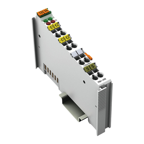
Pos: 18.4 /Serie 750 (WAGO-I/O-SYSTEM)/Gerätebeschreibung/Ansicht/Analogeingangsklemmen/Ansicht 750-0492 @ 20\mod_1407936960717_21.docx @ 161734 @ @ 1 Figure 1: View Pos: 18.5 /Serie 750 (WAGO-I/O-SYSTEM)/Gerätebeschreibung/Ansicht/Ansicht CageClamp®_Legende mit LEDs_ohne Leistungskontakte @ 16\mod_1371816091053_21.docx @ 124052 @ @ 1 Table 3: Legend for Figure “View” Pos. Description... -
Page 15: Connectors
Do not place the I/O modules on the gold spring contacts in order to avoid soiling or scratching! Pos: 18.9.3 /Serie 750 (WAGO-I/O-SYSTEM)/Wichtige Erläuterungen/Sicherheits- und sonstige Hinweise/Achtung/Achtung: ESD - Auf gute Erdung der Umgebung achten! @ 7\mod_1266318538667_21.docx @ 50708 @ @ 1 Ensure that the environment is well grounded! The devices are equipped with electronic components that may be destroyed by electrostatic discharge. -
Page 16: Cage Clamp ® Connectors
Pos: 18.13 /Serie 750 (WAGO-I/O-SYSTEM)/Gerätebeschreibung/Anschlüsse/CAGE CLAMP-Anschlüsse - Überschrift 3 @ 6\mod_1256296337770_21.docx @ 43674 @ 3 @ 1 ® 3.2.3 CAGE CLAMP Connectors Pos: 18.14 /Serie 750 (WAGO-I/O-SYSTEM)/Gerätebeschreibung/Anschlüsse/Analogeingangsklemmen/Anschlüsse 750-0475, -0477, -0479, -0480, -0483, -0492 @ 20\mod_1407938098672_21.docx @ 161748 @ @ 1 ® Figure 3: CAGE CLAMP Connectors ®... -
Page 17: Display Elements
Pos: 18.18 /Alle Serien (Allgemeine Module)/Überschriften für alle Serien/Gerätebeschreibung/Bedienelemente - Überschrift 2 @ 4\mod_1239191655456_21.docx @ 30439 @ 2 @ 1 Operating Elements Pos: 18.19 /Serie 750 (WAGO-I/O-SYSTEM)/Gerätebeschreibung/Bedienelemente/Bedienelemente Busklemme 750-xxxx nicht vorhanden @ 4\mod_1236322031125_21.docx @ 28063 @ @ 1 The I/O module 750-492 has no operating elements. -
Page 18: Schematic Diagram
Pos: 18.21 /Alle Serien (Allgemeine Module)/Überschriften für alle Serien/Gerätebeschreibung/Schematisches Schaltbild - Überschrift 2 @ 4\mod_1240984441312_21.docx @ 31967 @ 2 @ 1 Schematic Diagram Pos: 18.22 /Serie 750 (WAGO-I/O-SYSTEM)/Gerätebeschreibung/Schematische Schaltbilder/Analogeingangsklemmen/Schematisches Schaltbild 750-0492 @ 20\mod_1407940866257_21.docx @ 161758 @ @ 1 Figure 5: Schematic diagram Pos: 18.23 /Dokumentation allgemein/Gliederungselemente/---Seitenwechsel--- @ 3\mod_1221108045078_0.docx @ 21810 @ @ 1... -
Page 19: Technical Data
Pos: 18.24 /Alle Serien (Allgemeine Module)/Überschriften für alle Serien/Gerätebeschreibung/Technische Daten - Überschrift 2 @ 3\mod_1232967587687_21.docx @ 26924 @ 2 @ 1 Technical Data Pos: 18.25 /Serie 750 (WAGO-I/O-SYSTEM)/Gerätebeschreibung/Technische Daten/Analogeingangsklemmen/Technische Daten 750-0492 @ 20\mod_1408023699865_21.docx @ 161762 @ 3333 @ 1 </dg_ 3.6.1... -
Page 20: Inputs
All manuals and user guides at all-guides.com Device Description WAGO-I/O-SYSTEM 750 750-492 2AI 4-20mA Differential Input 3.6.4 Inputs Table 9: Technical data, inputs Number of inputs Connection types Differential measurement inputs electrically isolated Measured-value acquisition Time synchronous (both inputs) Signal current 4–20 mA... -
Page 21: Connection Type
Data contacts Slide contact, hard gold plated, self- cleaning Pos: 18.27 /Serie 750 (WAGO-I/O-SYSTEM)/Gerätebeschreibung/Technische Daten/Klimatische Umweltbedingungen/Technische Daten Klimat. Umweltbed. ohne erw. Temp. 0...55°C/-25...+85°C @ 5\mod_1247657968368_21.docx @ 37603 @ 3 @ 1 3.6.6 Climatic Environmental Conditions Table 12: Technical Data – Climatic Environmental Conditions Operating temperature range 0 °C …... -
Page 22: Approvals
> WAGO-I/O-SYSTEM 750 > System Description. Pos: 18.31 /Serie 750 (WAGO-I/O-SYSTEM)/Gerätebeschreibung/Zulassungen/Allgemein/Zulassungen Busklemme 750-xxxx Allgemein, ohne Variantenangabe - Einleitung @ 4\mod_1237460656921_21.docx @ 28643 @ @ 1 The following approvals have been granted to 750-492 I/O modules: Pos: 18.32.1 /Alle Serien (Allgemeine Dokumente) (Allgemeine Module)/Zulassungen/Standardzulassungen/CE (Konformitätskennzeichnung) @ 3\mod_1224494777421_21.docx @ 24276 @ @ 1... -
Page 23: Standards And Guidelines
750-492 2AI 4-20mA Differential Input Standards and Guidelines Pos: 18.39 /Serie 750 (WAGO-I/O-SYSTEM)/Gerätebeschreibung/Normen und Richtlinien/EMV-Normen Busklemme 750-xxxx, ohne Variantenangabe - Einleitung @ 4\mod_1242803944015_21.docx @ 33642 @ @ 1 750-492 I/O modules meet the following requirements on emission and immunity of interference: Pos: 18.40 /Alle Serien (Allgemeine Module)/Normen und Richtlinien/EMV-Normen - Standard/EMV CE-Störaussendung EN 61000-6-4 @ 4\mod_1242798273984_21.docx @ 33602 @ @ 1... -
Page 24: Process Image
Pos: 20 /Alle Serien (Allgemeine Module)/Überschriften für alle Serien/__ noch nicht einsortierte Überschriften müssen noch einsortiert werden __Prozessabbild - Überschrift 1 @ 4\mod_1240983067828_21.docx @ 31942 @ 1 @ 1 Process Image Pos: 21 /Serie 750 (WAGO-I/O-SYSTEM)/Prozessabbild Klemmenbus/Hinweis: Prozessabbildmapping abhängig von FBK/PFC, mit Status-/Controllbyte @ 4\mod_1242621308640_21.docx @ 33290 @ @ 1 Mapping of process data in the process image of fieldbus systems The representation of the I/O modules’... -
Page 25: Table 13: Process Image
All manuals and user guides at all-guides.com WAGO-I/O-SYSTEM 750 Process Image 750-492 2AI 4-20mA Differential Input Table 13: Process Image Numeric value Input current Status Byte Error 4 mA - 20 mA Hex. AI 1, 2 Binary FÜ Hex. Dec. -
Page 26: Mounting
I/O modules with power contacts (blade contacts) cannot be linked to I/O modules with fewer power contacts. Pos: 26.2 /Serie 750 (WAGO-I/O-SYSTEM)/Wichtige Erläuterungen/Sicherheits- und sonstige Hinweise/Achtung/Achtung: Busklemmen nur in vorgesehener Reihenfolge stecken! @ 6\mod_1256194177073_21.docx @ 43429 @ @ 1 Insert I/O modules only from the proper direction! All I/O modules feature grooves for power jumper contacts on the right side. -
Page 27: Inserting And Removing Devices
Mounting 750-492 2AI 4-20mA Differential Input Pos: 26.5 /Serie 750 (WAGO-I/O-SYSTEM)/Montieren/Demontieren/Geräte einfügen und entfernen - Überschrift 2 @ 3\mod_1231768483250_21.docx @ 25950 @ 2 @ 1 Inserting and Removing Devices Pos: 26.6 /Alle Serien (Allgemeine Module)/Wichtige Erläuterungen/Sicherheits- und sonstige Hinweise/Achtung/Achtung: Arbeiten an Geräten nur spannungsfrei durchführen! @ 6\mod_1256193963573_21.docx @ 43426 @ @ 1 Perform work on devices only if they are de-energized! Working on energized devices can damage them. -
Page 28: Removing The I/O Module
All manuals and user guides at all-guides.com Mounting WAGO-I/O-SYSTEM 750 750-492 2AI 4-20mA Differential Input Pos: 26.9 /Serie 750 (WAGO-I/O-SYSTEM)/Montieren/Demontieren/Busklemme entfernen @ 4\mod_1239169375203_21.docx @ 30334 @ 3 @ 1 5.2.2 Removing the I/O Module Remove the I/O module from the assembly by pulling the release tab. -
Page 29: Connect Devices
Pos: 28 /Alle Serien (Allgemeine Module)/Überschriften für alle Serien/Anschließen/Geräte anschließen - Überschrift 1 @ 3\mod_1234172889468_21.docx @ 27460 @ 1 @ 1 Connect Devices Pos: 29 /Serie 750 (WAGO-I/O-SYSTEM)/Anschließen/Leiter an CAGE CLAMP anschließen (allgemein) - Überschrift 2 und Text @ 3\mod_1225448660171_21.docx @ 24928 @ 2 @ 1 ®... -
Page 30: Connection Example
Pos: 31 /Alle Serien (Allgemeine Module)/Überschriften für alle Serien/Anschließen/Anschlussbeispiele - Überschrift 2 @ 4\mod_1240996036328_21.docx @ 32010 @ 2 @ 1 Connection Example Pos: 32 /Serie 750 (WAGO-I/O-SYSTEM)/Anschließen/Anschlussbeispiele/Analogeingangsklemmen/Anschlussbeispiele 750-0452, -0454, -0456, -0479, -0480, -0483, -0492 @ 16\mod_1378187494086_21.docx @ 130540 @ @ 1 Figure 10: Connection Example 750-492 Pos: 33 /Dokumentation allgemein/Gliederungselemente/---Seitenwechsel--- @ 3\mod_1221108045078_0.docx @ 21810 @ @ 1... -
Page 31: Use In Hazardous Environments
Pos: 34.1 /Alle Serien (Allgemeine Module)/Einsatz in Ex-Bereichen/Einsatz in explosionsgefährdeten Bereichen - Überschrift 1 @ 3\mod_1224075191281_21.docx @ 24084 @ 1 @ 1 Use in Hazardous Environments Pos: 34.2 /Serie 750 (WAGO-I/O-SYSTEM)/Einsatz in Ex-Bereichen/Einsatzbereich Serie 750 @ 3\mod_1234272230203_21.docx @ 27500 @ @ 1 The WAGO-I/O-SYSTEM 750 (electrical equipment) is designed for use in Zone 2 hazardous areas. -
Page 32: Marking Configuration Examples
Pos: 34.4 /Serie 750 (WAGO-I/O-SYSTEM)/Einsatz in Ex-Bereichen/Beispielhafter Aufbau der Kennzeichnung - Überschrift 2 @ 3\mod_1224157499140_21.docx @ 24182 @ 2 @ 1 Marking Configuration Examples Pos: 34.5 /Serie 750 (WAGO-I/O-SYSTEM)/Einsatz in Ex-Bereichen/Kennzeichnung für Europa gemäß ATEX und IEC-EX - Überschrift 3 @ 3\mod_1224157620203_21.docx @ 24185 @ 3 @ 1 7.1.1 Marking for Europe According to ATEX and IEC-Ex Pos: 34.6 /Serie 750 (WAGO-I/O-SYSTEM)/Einsatz in Ex-Bereichen/Beispielbedruckung der ATEX- und IEC-Ex-zugelassenen Busklemmen gemäß... -
Page 33: Table 14: Description Of Marking Example For Approved I/O Modules According To Atex And Iecex
All manuals and user guides at all-guides.com WAGO-I/O-SYSTEM 750 Use in Hazardous Environments 750-492 2AI 4-20mA Differential Input Table 14: Description of Marking Example for Approved I/O Modules According to ATEX and IECEx Printing on Text Description TÜV 07 ATEX 554086 X Approving authority and certificate numbers IECEx TUN 09.0001 X... -
Page 34: Figure 13: Side Marking Example For Approved Ex I I/O Modules According To
750-492 2AI 4-20mA Differential Input Pos: 34.8 /Serie 750 (WAGO-I/O-SYSTEM)/Einsatz in Ex-Bereichen/Beispielbedruckung der Ex-i- und IEC-Ex-i-zugelassenen Busklemmen gemäß CENELEC und IEC_2013 @ 14\mod_1360569320118_21.docx @ 111298 @ @ 1 Figure 13: Side Marking Example for Approved Ex i I/O Modules According to ATEX and IECEx. - Page 35 All manuals and user guides at all-guides.com WAGO-I/O-SYSTEM 750 Use in Hazardous Environments 750-492 2AI 4-20mA Differential Input Table 15: Description of Marking Example for Approved Ex i I/O Modules According to ATEX and IECEx Inscription Text Description TÜV 07 ATEX 554086 X Approving authority and certificate numbers IECEx TUN 09.0001X...
-
Page 36: Table 15: Description Of Marking Example For Approved Ex I I/O Modules According To Atex And Iecex
All manuals and user guides at all-guides.com Use in Hazardous Environments WAGO-I/O-SYSTEM 750 750-492 2AI 4-20mA Differential Input Table 15: Description of Marking Example for Approved Ex i I/O Modules According to ATEX and IECEx Gases Equipment group: All except mining... -
Page 37: Marking For America According To Nec 500
Use in Hazardous Environments 750-492 2AI 4-20mA Differential Input Pos: 34.10 /Serie 750 (WAGO-I/O-SYSTEM)/Einsatz in Ex-Bereichen/Kennzeichnung für Amerika gemäß NEC 500 - Überschrift 3 @ 3\mod_1224158423187_21.docx @ 24188 @ 3 @ 1 7.1.2 Marking for America According to NEC 500 Pos: 34.11 /Serie 750 (WAGO-I/O-SYSTEM)/Einsatz in Ex-Bereichen/Beispielbedruckung gemäß... -
Page 38: Installation Regulations
All manuals and user guides at all-guides.com Use in Hazardous Environments WAGO-I/O-SYSTEM 750 750-492 2AI 4-20mA Differential Input Pos: 34.13 /Alle Serien (Allgemeine Module)/Einsatz in Ex-Bereichen/Errichtungsbestimmungen - Überschrift 2 @ 3\mod_1232453624234_21.docx @ 26370 @ 2 @ 1 Installation Regulations Pos: 34.14 /Alle Serien (Allgemeine Module)/Einsatz in Ex-Bereichen/Errichtungsbestimmungen Einleitung_2013 @ 14\mod_1360582328318_21.docx @ 111371 @ @ 1... -
Page 39: Special Conditions For Safe Use (Atex Certificate Tüv 07 Atex 554086 X)
Use in Hazardous Environments 750-492 2AI 4-20mA Differential Input Pos: 34.16 /Serie 750 (WAGO-I/O-SYSTEM)/Einsatz in Ex-Bereichen/Besondere Bedingungen für den sicheren Ex-Betrieb gem. ATEX-Zertifikat TÜV 07 ATEX 554086_X_2013_2 @ 15\mod_1368620071975_21.docx @ 119778 @ 3 @ 1 7.2.1 Special Conditions for Safe Use (ATEX Certificate TÜV 07... -
Page 40: Special Conditions For Safe Use (Atex Certificate Tüv 12 Atex 106032 X)
WAGO-I/O-SYSTEM 750 750-492 2AI 4-20mA Differential Input Pos: 34.18 /Serie 750 (WAGO-I/O-SYSTEM)/Einsatz in Ex-Bereichen/Besondere Bedingungen für den sicheren Ex-Betrieb gem. ATEX-Zertifikat TÜV 12 ATEX 106032x_2013_2 @ 15\mod_1368620479454_21.docx @ 119782 @ 3 @ 1 7.2.2 Special Conditions for Safe Use (ATEX Certificate TÜV 12... -
Page 41: Special Conditions For Safe Use (Iec-Ex Certificate Tun 09.0001
Use in Hazardous Environments 750-492 2AI 4-20mA Differential Input Pos: 34.20 /Serie 750 (WAGO-I/O-SYSTEM)/Einsatz in Ex-Bereichen/Besondere Bedingungen für den sicheren Ex-Betrieb gem. IEC-Ex-Zertifikat TUN 09.0001 X_2013_2 @ 15\mod_1368620660911_21.docx @ 119786 @ 3 @ 1 7.2.3 Special Conditions for Safe Use (IEC-Ex Certificate TUN 09.0001 X) -
Page 42: Special Conditions For Safe Use (Iec-Ex Certificate Iecex Tun 12.0039 X)
WAGO-I/O-SYSTEM 750 750-492 2AI 4-20mA Differential Input Pos: 34.22 /Serie 750 (WAGO-I/O-SYSTEM)/Einsatz in Ex-Bereichen/Besondere Bedingungen für den sicheren Ex-Betrieb gem. IEC-Ex-Zertifikat TUN 12.0039 X_2013_2 @ 15\mod_1368620821493_21.docx @ 119790 @ 3 @ 1 7.2.4 Special Conditions for Safe Use (IEC-Ex Certificate IECEx TUN 12.0039 X) -
Page 43: Special Conditions For Safe Use According To Ansi/Isa
All manuals and user guides at all-guides.com WAGO-I/O-SYSTEM 750 Use in Hazardous Environments 750-492 2AI 4-20mA Differential Input Pos: 34.24 /Serie 750 (WAGO-I/O-SYSTEM)/Einsatz in Ex-Bereichen/Errichtungsbestimmungen ANSI ISA 12.12.01_2013_2 @ 15\mod_1368620942842_21.docx @ 119794 @ 3 @ 1 7.2.5 Special Conditions for Safe Use According to ANSI/ISA 12.12.01 “This equipment is suitable for use in Class I, Division 2, Groups A, B, C, D... -
Page 44: List Of Figures
All manuals and user guides at all-guides.com List of Figures WAGO-I/O-SYSTEM 750 750-492 2AI 4-20mA Differential Input Pos: 36 /Dokumentation allgemein/Verzeichnisse/Abbildungsverzeichnis - Überschrift oG und Verzeichnis @ 3\mod_1219222916765_21.docx @ 21080 @ @ 1 List of Figures Figure 1: View ....................... 14 Figure 2: Data Contacts .................. -
Page 45: List Of Tables
All manuals and user guides at all-guides.com WAGO-I/O-SYSTEM 750 List of Tables 750-492 2AI 4-20mA Differential Input Pos: 38 /Dokumentation allgemein/Verzeichnisse/Tabellenverzeichnis - Überschrift oG und Verzeichnis @ 3\mod_1219222958703_21.docx @ 21084 @ @ 1 List of Tables Table 1: Number Notation ..................8 Table 2: Font Conventions .................. - Page 46 All manuals and user guides at all-guides.com Pos: 40 /Dokumentation allgemein/Einband/Einband Handbuch - Rückseite @ 9\mod_1285229376516_21.docx @ 64944 @ @ 1 WAGO Kontakttechnik GmbH & Co. KG Postfach 2880 • D-32385 Minden Hansastraße 27 • D-32423 Minden Phone: +49/5 71/8 87 – 0 Fax: +49/5 71/8 87 –...
Need help?
Do you have a question about the 750 Series and is the answer not in the manual?
Questions and answers