Table of Contents
Advertisement
Quick Links
Instruction manual
Chamber machine C200
MC06
Serial number:
.........................................................
Service address:
Manufacturer:
MULTIVAC
Sepp Haggenmüller GmbH & Co. KG
Bahnhofstraße 4
D-87787 Wolfertschwenden, Germany
Tel.: 0049 8334 601 0
www.multivac.com
Date: 03.06.2014
The reproduction, distribution and utilization of this document as well as the communication of its contents to others without express authorization is
prohibited. Offenders will be held liable for the payment of damages. All rights reserved in the event of the grant of a patent, utility model or design.
Advertisement
Table of Contents

Related Manuals for multivac C200


Summary of Contents for multivac C200
- Page 1 Instruction manual Chamber machine C200 MC06 Serial number: ............Service address: Manufacturer: MULTIVAC Sepp Haggenmüller GmbH & Co. KG Bahnhofstraße 4 D-87787 Wolfertschwenden, Germany Tel.: 0049 8334 601 0 www.multivac.com Date: 03.06.2014 The reproduction, distribution and utilization of this document as well as the communication of its contents to others without express authorization is...
-
Page 2: Table Of Contents
Contents Contents Important information on the manual ..................6 Machine documentation ...................... 6 Changes not covered in the manual..................7 Symbols used........................7 Safety..........................9 General safety instructions..................9 1.1.1 Target group....................9 1.1.2 Unauthorised modifications and manufacture of spare parts....... 11 EC Conformity...................... - Page 3 Contents Menu tree ......................... 27 Process sequence....................27 Packaging process....................28 Preset recipes ......................28 Technical specifications ................... 29 Start-up..........................33 Setting up the machine and starting it up..............33 Operation ......................... 36 Switching on the machine ..................36 Switching off the machine ..................36 Packing products......................
- Page 4 Contents 6.1.2 Instructions for maintaining the machine's value ......... 49 6.1.3 Instructions on the handling of cleansers............. 50 6.1.4 Instructions on the handling of disinfectants ..........50 6.1.5 Instructions on the handling of anti-corrosion agents and lubricants ... 51 6.1.6 Instructions on the handling of cleaning devices..........
- Page 5 Contents Spare parts........................83 Glossary ............................ 86 MULTIVAC branch offices......................89 03.06.2014...
-
Page 6: Important Information On The Manual
• Do not work with the machine until you have read through the manual and completely understood its contents. • Please contact MULTIVAC as soon as possible if there is some- thing you do not understand in the manual! Your comments will help us to further improve the manual. -
Page 7: Changes Not Covered In The Manual
Important information on the manual Changes not covered in the manual Changes not covered in the manual Continuous development is the foundation for ensuring that our ma- chines are technically advanced and of high quality. For this reason, you may discover slight deviations between the specifications in the manual and your machine. - Page 8 Important information on the manual Symbols used Instructions to follow are displayed in the following form: Press key A. Release screw B. Press key C. • Enumerated items are marked with bullet points. – Dashes are used to mark sub-items of enumerated lists or se- quences of steps to be taken.
-
Page 9: Safety
Safety Safety General safety instructions The machine incorporates the latest technological principles. Never- theless, potential hazards for persons, the machine and other materi- als cannot be entirely excluded. • Before you start up the machine, read through the instruction manual and follow the instructions contained therein. •... - Page 10 Safety General safety instructions • The persons can ensure that the machine remains capable of op- eration. • The persons can perform maintenance work and inspections. The persons, who carry out work on electrical components, must have as a minimum requirement the following capabilities, knowledge and competence: •...
-
Page 11: Unauthorised Modifications And Manufacture Of Spare Parts
Genuine MULTIVAC spare parts and accessories provide the highest level of safety for personnel. Parts and equipment from other manu- facturers have not been tested by MULTIVAC and are therefore not approved. The use of such components can alter the properties of the machine and thereby impair safe operation. -
Page 12: Ec Conformity
Machinery Directive 2006/42/EC (exception: industrial trucks such as lift trucks and die changing trolleys). Agent authorised to compile the relevant technical documentation according to Directive 2006/42/EC: MULTIVAC Sepp Haggenmüller GmbH & Co. KG Department of Technical Services Bahnhofstraße 4 87787 Wolfertschwenden, Germany Manufacturer: MULTIVAC Sepp Haggenmüller GmbH &... -
Page 13: Electromagnetic Compatibility (Emc)
Safety Intended use Any other use is considered improper and can endanger persons, the product and the machine. 1.3.1 Electromagnetic compatibility (EMC) The machine has been designed for use in residential, business and industrial areas (without a separate power substation, it can be con- nected directly to the public mains). -
Page 14: Residual Risks
Safety Warning against incorrect use – Cleaning work. – Maintenance work. • Use of third-party parts, i.e. parts that are not MULTIVAC spare parts. • Operation under prohibited ambient conditions. Residual risks The safety instructions in this manual serve as guidelines for trained operating personnel in safe working practice with the machine. -
Page 15: Making The Selection Of Personnel
If necessary, order an instruction manual from the manufacturer in the appropriate official language. • Inform the personnel about measures for avoiding hygiene risks. • MULTIVAC offers appropriate training courses. 1.7.5 Providing personal protective equipment The operating company must ensure that the operators wear the re- quired personal protective equipment (foot protection, head gear, gloves, etc.) in accordance with the national directives which apply. -
Page 16: Provide Power Supply
Safety Obligations of the operating company 1.7.8 Provide power supply Connect the machine to the mains electricity at an always easily ac- cessible place. In the case of an emergency the machine must be capable of being disconnected immediately from the mains electricity. The power supply must be equipped as follows: •... -
Page 17: 1.7.10 Avoiding Hygiene Risks
Safety Obligations of the operating company • The operating company must ensure that the input and operating pressures given in the Technical specifications are adhered to and not exceeded. Personnel qualifications Only qualified persons with the corresponding required training, ex- perience and reliability may perform work on the gas supply. -
Page 18: 1.7.11 Checking The Packs
Safety Obligations of the operating company Health hazard! Insufficient or sporadic cleaning can promote the growth of micro- organisms which can change unfavourably the product that is to be WARNING packed. This can severely damage the health of people, especially of the consumers. -
Page 19: 1.7.12 Pump Protection Function
Safety Obligations of the operating company • Damage to the pack caused e.g. by sharp-edged products. Time of inspection • After machine start-up. • When a defined time interval was reached during running opera- tion. • When the pack size was changed. •... - Page 20 Safety Machine label • Make sure all labels are intact and legible. • If necessary, clean the labels with soap and water. – Do NOT clean the labels with solvents. • Replace damaged, scratched or illegible labels with new ones. Info Labels can be obtained from the manufacturer.
-
Page 21: Description
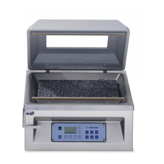
Description Description Construction of the machine Fig. 7: Construction of the machine Chamber lid Chamber lid gasket Counter-pressure bar Chamber with spacer plates and sloping insert with support angle Sealing bar with inert gas nozzles (optional) (Optional) Inert gas connection Power supply Vacuum pump Oil sight glass... -
Page 22: Control Terminal
Description Control terminal Control terminal Fig. 8: Control terminal <Machine control On/Off> key Display Keys <Arrow key> Keys <1> to <6> <Function selection> key <Sealing> key <Gas flushing> key <Evacuation> key <Stop> key <Machine control • Switch machine control on and off. On/Off>... -
Page 23: Display
Description Control terminal <Sealing> key • Press and hold down: Call up "Sealing" menu. • Press briefly: Call up values for sealing. • Confirm the configuration code. • In the MPP process: select the value. <Gas flushing> key • In the MPP process: select the function. In machines with the inert gas option: •... -
Page 24: Status Display
Description Display Fig. 9: Startup display Type designation of machine control Software version Configuration code 2.3.2 Status display Process data status display The process data status display shows information on the last pack- aging procedure. Fig. 10: Process data status display Current access right (lock closed = user;... -
Page 25: Function Display
Description Display Fig. 11: Evacuation status display (047) Fig. 12: Gas flushing status display (049) Fig. 13: Sealing status display (050) 2.3.3 Function display Depending on the access rights, the function display will offer the following options: • View values. •... -
Page 26: Diagnostic Display
Description Display Fig. 15: Function display on/off (013) Selected function Switch status Symbol of function (e.g. sealing) 2.3.4 Diagnostic display Fig. 16: Diagnostic display Diagnostic number Type of error acknowledgement Error text (in ticker) Eliminate the malfunction, see Section 8 "T ". -
Page 27: Menu Tree
Description Menu tree Menu tree Fig. 17: Menu tree Process sequence The film pouches are filled and laid in the chamber. When the cham- ber is closed, the following procedures run automatically: Evacuation Evacuation if chamber and film pouches. Gas flushing (optional) Infeed of inert gas. 03.06.2014... -
Page 28: Packaging Process
Description Process sequence Sealing • Compressed air is admitted to the sealing diaphragm. The sealing diaphragm ex- pands, pressing the sealing bar against the counter-pressure bar. • The film pouch is sealed. • The sealing bar and seal seam cool off. •... -
Page 29: Technical Specifications
Description Preset recipes Recipe Example of Evacuation Automatic Gas flush- Sealing pressure sensitivity ing pres- time sure No. 3 For dry Automatic 100 mbar to 1.8 s products 150 mbar with little gas flush- ing. No. 4 For dry Automatic 250 mbar 1.8 s products... - Page 30 Description Technical specifications Dimensions Height (a) with closed chamber 370 mm Width (b) 560 mm Depth (c) 520 mm Operating height approx. 256 mm Effective chamber size (W/H/D) 465 mm/150 mm (optional 220 mm)/355 mm Sealing length 465 mm Weight approx. 70 kg Fig.
- Page 31 Description Technical specifications Inert gas (option) Max. input pressure 2.5 bar Min. input pressure 0.7 bar Inner diameter of supply line 8 mm Vacuum pump Nominal suction capacity • 20 m • 21 m Achievable final pressure approx. 2 mbar Noise exposure at the workplace Based on Machinery Directive...
- Page 32 Description Technical specifications Noise exposure at the workplace Fig. 19: Noise exposure measuring point Info The measured values of the noise data have been adjusted to take extraneous and ambient noises into account. Higher measured values may be produced as a result of the follow- ing: •...
-
Page 33: Start-Up
Start-up Start-up Setting up the machine and starting it up Danger of explosion! Operating the machine in a potentially explosive atmosphere can result in explosion due to hot machine parts. DANGER Explosions can cause serious injuries or even death. Do NOT use the machine in rooms that are exposed to explo- sion hazards. - Page 34 Start-up Setting up the machine and starting it up Unscrew the screw plug. To do so, turn the screw plug anticlock- wise. Fill the vacuum pump with the oil supplied up to the middle of the oil sight glass. – The oil level is then approximately in the middle of the oil sight glass.
- Page 35 Start-up Setting up the machine and starting it up Danger of explosion! Gas mixtures with oxygen proportions over 21% are explosive. A gas mixture with an oxygen proportion over 21 % can cause an DANGER explosion and fire if it comes in contact with heat, oil or grease. Do NOT use a gas mixture with an oxygen proportion of over 21%.
-
Page 36: Operation
Operation Operation Switching on the machine Before switching on the machine for the first time fill the vacuum pump with oil, see Section 7 "M ". AINTENANCE If present, open the stop-cock for the gas supply. Connect the machine to the mains electricity at a place which is always easily accessible. -
Page 37: Packing Products
Operation Packing products Packing products Open the chamber lid. If necessary, use filling plates. – The pouch neck should be located at the centre of the pouch height x. Use the sloping insert for packaging liquids, see Section 5.1 "I ". - Page 38 Operation Packing products Gas flushing option: Pull the pouch opening over the gas nozzles so that the inert gas flows into the film pouch. Pull the pouch neck flat on the sealing bar. – The pouch neck lies on the sealing bar without creases. NOTICE Danger of material damage! Penetration by foreign matter (e.g.
-
Page 39: Opening And Closing Menus
Operation Packing products Remove the finished pack. Check the pack. Info Visually inspect the packs on a regular basis while the machine is running. Depending on product and pack it may be necessary to carry out additional and considerably more complex test proce- dures. -
Page 40: Quitting Menus
Operation Opening and closing menus 4.4.2 Quitting menus Using the <arrow> keys, select the respective menu heading. – The text of the menu heading changes and becomes the (menu) function quit. Press the <function selection> key. – The menu is exited and the system changes to the next highest display level. -
Page 41: Change Password For Authorisation Access Creator
Operation Selecting and resetting access rights 4.6.3 Change password for authorisation access creator Call up "PIN" menu. Select Change PIN. Enter old password with keys <1> to <6>. Enter new password with keys <1> to<6>. Confirm the new password again. –... -
Page 42: Working With Recipes
Operation Language selection Press the <function selection> key. – The language is activated. Working with recipes 4.8.1 Load recipe Info If no recipe is saved, the message “recipe missing” appears. The last settings remain active. Load using keys <1> to <6>... -
Page 43: Delete Recipe
Operation Working with recipes Saving via keys <1> to <6> Press and hold down desired key <1> to <6>. – The message "Recipe saved" appears. – The current values are stored in the selected recipe. Saving via the “save recipe” menu Call up "Recipe, saving"... -
Page 44: To Set Mcv Process
Operation Select and set process Call up the "gas flushing" menu (Optional). Switch on On/off gas flushing. Set Distribution time. Set Rinse time. Press <Gas flushing> key briefly and set value for Gas flushing pressure. 4.9.2 To set MCV process Press <Evacuation>... -
Page 45: Modifying And Resetting Machine Cycles
Operation Entering basic settings Set Ventilate diaphragm. 4.12 Modifying and resetting machine cycles Call up the "operating data" menu. Call up "Counter" menu. Call up machine cycles. Set the value with the <arrow> keys or set to "0". – The set value is adopted. 4.13 Display production data 4.13.1 Display total cycles of the machine... -
Page 46: 4.13.4 Show Settings
Operation Display production data 4.13.4 Show settings To view the settings of recipes 7 through 30, load the desired rec- ipe via the menu, see Section 4.8.1 "L ". OAD RECIPE Call up the "production data" menu. Select Settings . –... -
Page 47: Adjustment Work And Setup
Adjustment work and setup Adjustment work and setup Insert and remove the sloping insert If necessary, use filling plates for the desired incline. Hook the sloping insert on the screws of the sealing bar. Attach the support angle to the sloping insert at the required posi- tion. -
Page 48: Cleaning
– Recommendations for the course of the daily cleaning. – Recommendations for the course of the intensive cleaning. – Qualifications of the cleaning personnel. Assign only suitably qualified and instructed personnel. Information on qualification and training can be obtained from MULTIVAC Service. • First aid measures. 03.06.2014... -
Page 49: Instructions For Maintaining The Machine's Value
Cleaning Notes on cleaning 6.1.2 Instructions for maintaining the machine's value Regular and proper care helps to maintain the machine's value. The best protection against harmful influences is to clean and disinfect the machine on a regular basis. The longer product residue and other aggressive deposits remain on the machine, the more harmful their corrosive effects will be. -
Page 50: Instructions On The Handling Of Cleansers
Cleaning Notes on cleaning • The temperature of the water must NOT exceed 60 °C (140 °F). • Only rinse off with water of drinking quality. 6.1.3 Instructions on the handling of cleansers Chemical burn hazard! Acidic cleansers are caustic. Caustic effects are NOT noticed im- mediately. -
Page 51: Instructions On The Handling Of Anti-Corrosion Agents And Lubricants
Cleaning Notes on cleaning 6.1.5 Instructions on the handling of anti-corrosion agents and lubricants Excess lubricants can accumulate at lubrication points. Excess grease has no lubricating function; however, it can breed micro- organisms and contaminate the product. • For type of anti-corrosion agent, refer to "Care products table". •... - Page 52 Cleaning Cleaning recommendations Store empty, new film pouches outside the room in a clean, dry place during the cleaning procedure. Remove all waste (e.g. product scraps, film trim) on or around the machine. Remove the following components: – Sloping insert with with support angle. –...
- Page 53 Cleaning Cleaning recommendations Take the removed components to a separate room suitable for wet cleaning. Clean dismantled components manually with cleaning solution. Only clean the Teflon tape of the sealing bar manually with a soft cloth or a soft brush. Thoroughly clean the inert gas nozzles.
- Page 54 Cleaning Cleaning recommendations Only clean the chamber lid manually with a soft cloth or a soft brush. Wait until the application time has elapsed (see instructions of cleanser manufacturer). Wipe with new cloth and water of drinking quality. Inspect the entire machine and the floor for dirt and cleanser resi- dues.
- Page 55 Cleaning Cleaning recommendations Disinfect entire chamber with alcohol-based disinfectant. Dry a wet chamber lid gasket or groove with a new cloth or blow them dry with sterile compressed air. Install the chamber lid gasket. Press the chamber lid gasket into the groove of the chamber lid.
-
Page 56: Care Products Table
Cleaning Cleaning recommendations Leave the chamber lid open to dry. If present, open the stop-cock for the gas supply. Connect the machine to the mains electricity. Clean the cleaning devices (e.g. rubber wipers, brushes). Place cleaning devices in disinfectant solution. Unpack the film pouches and lay them ready. - Page 57 Cleaning Care products table Type Manufacturer Designation Cleansers, acidic Ecolab Europa P3-topax 52 P3-topax 56 Ecolab USA Quorum Red Foam shine Diversey Europe JD Acifoam VF10 Diversey USA Disinfectants Ecolab Europa P3-topax 91 P3-topax 990 Ecolab USA Ster-Bac Diversey Europe JD Divosan extra VT55 JD Suredis VT1 Diversey USA...
-
Page 58: Maintenance
Maintenance Maintenance Dangerous voltage! Switching off the machine does not rid it of electrical current. Touching electrically charged components can cause serious or DANGER even fatal injuries. Before performing any cleaning or service work: Disconnect the machine's power supply from the mains electric- ity. -
Page 59: Maintenance Recommendation
Maintenance Maintenance schedule Page Complet Every 1000 opearating hours or yearly Page Complet Vacuum pump Oil change Vacuum pump Exchanging the air de-oiling element Entire machine Check the age Maintenance recommendation 7.2.1 Entire machine - Perform a wipe test Check the result of the cleaning and disinfection by means of a wipe test. -
Page 60: Entire Machine - Alkaline Cleaning And Disinfection
Maintenance Maintenance recommendation If necessary, replace the sealing bar, see Section 7.3 "R ". PLACE THE SEALING BAR Check the counter-pressure bar for damage. If necessary, repair the counter-pressure bar, see Section 7.4 "R ". EPAIR COUNTER PRESSURE BAR 7.2.4 Entire machine - Alkaline cleaning and disinfection See company cleaning guidelines and see Section 6 "C ". -
Page 61: Vacuum Pump - Exchanging The Air De-Oiling Element
7.2.11 Entire machine - Check the age Read the year of manufacture on the type plate. If the machine is older than 19 years: Shut down the machine. Have the safety functions checked by MULTIVAC Service. Replace the sealing bar 7.3.1 Remove the sealing bar Switch off the machine. -
Page 62: Repair Counter-Pressure Bar
Maintenance Replace the sealing bar Install the sealing bar in such a way that the screws on the sealing bar point to the middle of the chamber. Repair counter-pressure bar Open the chamber lid. Pull the profile thread together with the Teflon tape out of the counter-pressure bar. - Page 63 Maintenance Repair counter-pressure bar Remove the glue residue from the profile thread. Cut the new Teflon tape to fit the length of the profile thread. Press the ends of the profile thread into the counter-pressure bar so that they are flush. Press the profile thread into the centre of counter-pressure bar.
-
Page 64: Change The Oil In The Vacuum Pump
Maintenance Repair counter-pressure bar Clean the profile thread. – The profile thread should be free of dirt and grease. Stick the new Teflon tape onto the dry profile thread so that it ad- heres without bubbles or creases. Change the oil in the vacuum pump 7.5.1 Drain oil Switch off the machine. -
Page 65: Filling The Vacuum Pump With Oil
Maintenance Change the oil in the vacuum pump Hold the liquid container (e.g. an empty oil bottle) under the drain opening. Unscrew the screw plug. To do so, turn the screw plug anticlock- wise. Drain the oil completely. Wipe off any oil from the machine. Turn the screw plug in the drain opening and screw it tight. - Page 66 Maintenance Change the oil in the vacuum pump Burn hazard! The surface of the vacuum pump can reach temperatures of over 70 °C during operation. WARNING Touching the vacuum pump can lead to burns. Before performing any work on the vacuum pump: Allow the vacuum pump to cool down.
-
Page 67: Change The Air De-Oiling Element
Maintenance Change the oil in the vacuum pump Info Only use low odour synthetic oil if food is being packed. Check oil level on the oil sight glass: – The oil level is then approximately in the middle of the oil sight glass. - Page 68 Maintenance Change the air de-oiling element Burn hazard! The surface of the vacuum pump can reach temperatures of over 70 °C during operation. WARNING Touching the vacuum pump can lead to burns. Before performing any work on the vacuum pump: Allow the vacuum pump to cool down.
- Page 69 Maintenance Change the air de-oiling element Unscrew the screw plug or the screws on the cover. Turn these screws anticlockwise. For vacuum pump RB 0021: Undo the screw until the tension springs rotate clockwise and can be removed. 03.06.2014...
- Page 70 Maintenance Change the air de-oiling element Pull out the air de-oiling element. Insert a new air de-oiling element. For vacuum pump MRP20: Place the screw plug, together with the spring, on the nozzle of the air de-oiling element and tighten it. Turn this screw clockwise. –...
-
Page 71: Change Chamber Lid Gasket
Maintenance Change the air de-oiling element Close the bottom section and fix it with the screws. Fasten the safety guard. Change chamber lid gasket Open the chamber lid. Remove the chamber lid gasket from the groove. 03.06.2014... -
Page 72: Performing The Vacuum Test
Maintenance Change chamber lid gasket Press the new chamber lid gasket into the groove of the chamber lid. – The beginning and end of the chamber lid gasket must butt up against each other without a gap. During insertion, do not stretch the chamber lid gasket. Smooth out chamber lid gasket. - Page 73 Maintenance Performing the vacuum test Close and press down the chamber lid. – The evacuation system is being checked. – The processes in the machine run automatically. – The corresponding diagnostic message appears. – The chamber lid opens. Acknowledge the diagnostic message. –...
-
Page 74: Troubleshooting
Troubleshooting Troubleshooting Injury hazard! Ignorance of proper machine handling is very dangerous. Improper handling can lead to serious injuries. WARNING For all service and repair work: Make sure you observe the safety instructions and accident prevention regulations. Disconnect the unit's power supply from the mains electricity. Only qualified electricians are permitted to work on electrical modules. -
Page 75: Faults Without Diagnostic Message
Troubleshooting Malfunctions with diagnostic message Symptom Cause Solution • Vacuum hose between the • Notify the service. chamber and the vacuum sensor is clogged, missing or leaking. • Vacuum hose is loose, leaking • Notify the service. or clogged. • Chamber lid gasket is not air- •... - Page 76 Troubleshooting Faults without diagnostic message Symptom Cause Solution • Gas flushing pressure is set • Reduce Gas flushing pressure too high. value. • Gas flushing time is set too • Reduce Gas flushing time high. value. • Pouch neck is clamped by •...
- Page 77 Troubleshooting Faults without diagnostic message Symptom Cause Solution • The pressure difference be- • Reduce Evacuation pressure tween the chamber and the value. outside environment is not • Reduce Gas flushing pressure large enough before the seal- value. ing process. •...
-
Page 78: Shutdown, Transport, Storage
Shutdown, transport, storage Shutdown, transport, storage Info Observe the safety instructions, see Section 1 "S ". AFETY Taking the machine out of service Disconnect the machine from the mains electricity. If present, close the stop-cock for the gas supply and detach the gas hose from the inert gas connection. -
Page 79: Storing The Machine
Shutdown, transport, storage Storing the machine Storing the machine Shutting down the machine. Select a suitable storage site. Observe the ambient conditions for storing the machine, see Technical specifications. Ensure that the location site is of adequate load-bearing capac- ity and keep the weight of the unit in mind, see Technical speci- fications. -
Page 80: Disposal
Disposal Disposal 10.1 Disposing of the machine Info • Sealing bars can be reused on other machines of the same se- ries. • If disposal of the machine is not handled by the manufacturer, dispose of the machine as described below. Disconnect the machine from the mains electricity, see Section 9 "S ". -
Page 81: 10.2.2 Disposing Of Packaging Materials
Disposal Dispose of operating materials 10.2.2 Disposing of packaging materials Info Packaging materials are resource materials that can be recycled. • Improper disposal is harmful to the environment. • Films should be collected for recycling. • Follow the disposal instructions of the packaging material manu- facturer. - Page 82 Disposal Dispose of operating materials Info Improper disposal is harmful to the environment. • Observe the safety data sheets of the cleanser and disinfectant manufacturers. • Follow the disposal instructions of the cleanser and disinfectant manufacturers. • Observe regionally applicable disposal regulations. 03.06.2014...
- Page 83 Spare parts Spare parts Fig. 20: Spare parts drawing (SAP-DIS 16000022467) 03.06.2014...
- Page 84 Spare parts Item Material number Designation Quantity and unit of measure- ment 105893127 Round cord (chamber lid gasket), for cham- 2.0 m ber height 150 mm 81863140000 Profile thread (chamber lid gasket), for 2.0 m chamber height 230 mm 105003538 Tension spring for chamber height 230 mm 2 pc.
- Page 85 Spare parts Item Voltage Frequency Material number R5-RB0021 220 V to 230 V 60 Hz 80121402816 R5-RB0021 230 V 50 Hz 80121402814 MRP20 100 V to 115 V 50 Hz to 60 Hz 106688697 MRP20 220 V to 240 V 50 Hz to 60 Hz 106688695 03.06.2014...
- Page 86 Glossary Glossary Automatic If the function Automatic is set, the machine will reach the optimum evacuation time and pressure depending on the product. The automatic evacuation is suitable for the following cases: • Achieving the best possible vacuum for long shelf life. •...
- Page 87 Glossary Evacuation pressure Is the pressure to which the film pouch and the chamber are evacu- ated. The pressure is measured in the chamber. Evacuation to a pre-determined pressure is suitable for the following cases: • Achieving a package result which is different from that of the op- timum evacuation pressure.
- Page 88 Glossary Vacuum pump - Pro- Counts the vacuum pump's hours of operation. Counting starts as duction data soon as the vacuum pump is turned on. The display cannot be changed. Vacuum test Automatic leakage test of the vacuum system and the sealing dia- phragm.
- Page 89 MULTIVAC branch offices MULTIVAC branch offices GERMANY MULTIVAC Sepp Haggenmüller GmbH & Co. KG Tel.: +49 83 34 601 0 Fax:+49 83 34 601 199 multivac@multivac.de www.multivac.com SWITZERLAND MULTIVAC EXPORT AG Tel.: +41 41 785 65 65 Fax:+41 41 785 65 10 meag@multivac.ch...
- Page 90 INDIA IRELAND ISRAEL MULTIVAC Laraon India Pri- MULTIVAC Ireland Ltd. MULTIVAC B.P.S. Ltd. vate Limited Tel.: +353 (0) 1 4133200 Tel.: +972 46 344 68 1 Tel.: +91 12 446 10 000 Fax:+353 (0) 1 4133205...
- Page 91 MULTIVAC branch offices AUSTRIA POLAND PORTUGAL MULTIVAC Vertriebsgesell- MULTIVAC Sp. z o. o. Multi Vacuo - Sistemas de Embal- schaft mbH Tel.: +48 81 746 67 00 agens Lda. Tel.: +43 (0)1 698 1300 Fax:+48 81 746 67 01 Tel.: +351 21 41 95 541 Fax:+43 (0)1 698 1300-99 mupl@multivac.pl...
- Page 92 MULTIVAC branch offices HUNGARY UNITED ARAB EMIRATES MULTIVAC Hungária Kft. MULTIVAC, Inc. MULTIVAC Middle East (FZE), Tel.: +36 23 500 28 7 Tel.: +800 877 5200 Amir Sotoudeh Fax:+36 23 500 28 8 Tel.: +1 816 891 0555 Tel.: +971 4 299 1980 info@hu.multivac.com...
Need help?
Do you have a question about the C200 and is the answer not in the manual?
Questions and answers