Table of Contents
Advertisement
Quick Links
Instruction manual
Chamber machine C300
MC06
Serial number:
.........................................................
Service address:
Manufacturer:
MULTIVAC
Sepp Haggenmüller GmbH & Co. KG
Bahnhofstraße 4
D-87787 Wolfertschwenden, Germany
Tel.: 0049 8334 601 0
www.multivac.com
Date: 10.06.2014
The reproduction, distribution and utilization of this document as well as the communication of its contents to others without express authorization is
prohibited. Offenders will be held liable for the payment of damages. All rights reserved in the event of the grant of a patent, utility model or design.
Advertisement
Table of Contents

Related Manuals for multivac C300


Summary of Contents for multivac C300
- Page 1 Instruction manual Chamber machine C300 MC06 Serial number: ............Service address: Manufacturer: MULTIVAC Sepp Haggenmüller GmbH & Co. KG Bahnhofstraße 4 D-87787 Wolfertschwenden, Germany Tel.: 0049 8334 601 0 www.multivac.com Date: 10.06.2014 The reproduction, distribution and utilization of this document as well as the communication of its contents to others without express authorization is...
-
Page 2: Table Of Contents
Contents Contents Important information on the manual ..................7 Machine documentation ...................... 7 Changes not covered in the manual..................8 Symbols used........................8 Manual layout ........................9 Safety..........................10 General safety instructions..................10 1.1.1 Target group....................10 1.1.2 Unauthorised modifications and manufacture of spare parts....... 12 EC Conformity...................... - Page 3 Contents Control terminal......................32 Optional equipment ....................34 2.3.1 Pouch clamp ....................34 2.3.2 Suction throttle ..................... 34 2.3.3 Holder for gas cylinder ................. 35 Display ........................35 2.4.1 Startup display ..................... 35 2.4.2 Status display....................36 2.4.3 Menu display ....................37 2.4.4 Function display ...................
- Page 4 Contents 4.8.4 Delete recipe ....................60 Select and set process..................... 61 4.9.1 Set standard process ................... 61 4.9.2 To set MCV process..................61 4.9.3 Setting the MHP process ................62 4.9.4 Setting the MPP process................62 4.9.5 Set MRP process ..................63 4.10 Setting the sealing....................
- Page 5 Contents 7.2.5 Entire machine - Acidic cleaning and disinfection ........93 7.2.6 Entire machine - Intensive cleaning ............. 93 7.2.7 Chamber lid viewing window - Visual inspection.......... 93 7.2.8 Chamber lid gasket - Visual inspection ............93 7.2.9 Sealing bars - Visual inspection ..............94 7.2.10 Connections - Visual inspection ..............
- Page 6 Contents 10.2.2 Disposing of packaging materials .............. 117 10.2.3 Dispose of chemicals ................. 117 Spare parts........................119 Glossary ..........................123 Index ............................133 MULTIVAC branch offices...................... 137 10.06.2014...
-
Page 7: Important Information On The Manual
• Do not work with the machine until you have read through the manual and completely understood its contents. • Please contact MULTIVAC as soon as possible if there is some- thing you do not understand in the manual! Your comments will help us to further improve the manual. -
Page 8: Changes Not Covered In The Manual
Important information on the manual Changes not covered in the manual Changes not covered in the manual Continuous development is the foundation for ensuring that our ma- chines are technically advanced and of high quality. For this reason, you may discover slight deviations between the specifications in the manual and your machine. -
Page 9: Manual Layout
Important information on the manual Symbols used Instructions to follow are displayed in the following form: Press key A. Release screw B. Press key C. • Enumerated items are marked with bullet points. – Dashes are used to mark sub-items of enumerated lists or se- quences of steps to be taken. -
Page 10: Safety
Safety Safety General safety instructions The machine incorporates the latest technological principles. Never- theless, potential hazards for persons, the machine and other materi- als cannot be entirely excluded. • Before you start up the machine, read through the instruction manual and follow the instructions contained therein. •... - Page 11 Safety General safety instructions • The persons can ensure that the machine remains capable of op- eration. • The persons can perform maintenance work and inspections. The persons, who carry out work on electrical components, must have as a minimum requirement the following capabilities, knowledge and competence: •...
-
Page 12: Unauthorised Modifications And Manufacture Of Spare Parts
Genuine MULTIVAC spare parts and accessories provide the highest level of safety for personnel. Parts and equipment from other manu- facturers have not been tested by MULTIVAC and are therefore not approved. The use of such components can alter the properties of the machine and thereby impair safe operation. -
Page 13: Ec Conformity
Machinery Directive 2006/42/EC (exception: industrial trucks such as lifting trolleys and die changing trolleys). Agent authorised to compile the relevant technical documentation according to Directive 2006/42/EC: MULTIVAC Sepp Haggenmüller GmbH & Co. KG Department of Technical Services Bahnhofstraße 4 87787 Wolfertschwenden, Germany Manufacturer: MULTIVAC Sepp Haggenmüller GmbH &... -
Page 14: Intended Use
Safety EC Conformity Manufacturer: MULTIVAC Packaging Systems España, S.L. Avda. Sot de les Vernedes, 22-26 E-08396 Sant Cebrià de Vallalta Plant Manager: Txus Baquero Intended use The machine is a piece of technical equipment to be used exclusively as a working appliance. The machine may only be operated by per- sons older than 14 years of age. -
Page 15: Warning Against Incorrect Use
• Neglecting the following work tasks: – Inspections. – Cleaning work. – Maintenance work. • Use of third-party parts, i.e. parts that are not MULTIVAC spare parts. • Operation under prohibited ambient conditions. Residual risks The safety instructions in this manual serve as guidelines for trained operating personnel in safe working practice with the machine. -
Page 16: Monitoring Obligation
• Make the machine instruction manual accessible to the personnel. If necessary, order an instruction manual from the manufacturer in the appropriate official language. • Inform the personnel about measures for avoiding hygiene risks. • MULTIVAC offers appropriate training courses. 10.06.2014... -
Page 17: Providing Personal Protective Equipment
Safety Obligations of the operating company 1.7.5 Providing personal protective equipment The operating company must ensure that the operators wear the re- quired personal protective equipment (foot protection, head gear, gloves, etc.) in accordance with the national directives which apply. In Europe the directive 89/656/EEC specifies the minimum mandatory requirements for the use of personal protective equipment. -
Page 18: Avoiding Hygiene Risks
Safety Obligations of the operating company General requirements • The operating company is obliged to connect the gas supply in a way that poses no danger to employees or third parties. • The operating company is obliged to create an instruction manual with all safety-related information for the following phases in the service life of the machine: –... -
Page 19: Checking The Packs
Safety Obligations of the operating company product to be packed, and the person must then implement these regulations. The manufacturer assumes no liability whatsoever for any warranty claims and damage claims of any kind resulting from insufficient hy- giene and insufficient cleaning. Health hazard! Insufficient or sporadic cleaning can promote the growth of micro- organisms which can change unfavourably the product that is to be... -
Page 20: Testing Pressure Equipment
Safety Obligations of the operating company The following faults can result in a pack not being airtight: • A leaky seal seam. Possible reasons: – The inside of the packaging material is contaminated by product in the seal seam area. –... - Page 21 WARNING Unprotected danger zones can cause serious or even fatal injuries. Do NOT alter the safety devices. Use only MULTIVAC spare parts and accessories. Before switching on the machine each time: Check that all safety guards close completely and prevent reaching into the danger zones.
-
Page 22: Control Cabinet
Safety Danger zones 1.8.1 Control cabinet Dangerous voltage! The control cabinet contains electrically charged components. Vari- ous components are still under a dangerous voltage even after the DANGER machine has been switched off. Touching electrically charged components can cause serious or even fatal injuries. - Page 23 Safety Safety devices Fig. 3: Safety devices, front view Main switch (option) Protective device Fig. 4: Safety devices, rear view Protective device 10.06.2014...
-
Page 24: Main Switch
WARNING Unprotected danger zones can cause serious or even fatal injuries. Do NOT alter the safety devices. Use only MULTIVAC spare parts and accessories. Before switching on the machine each time: Check that all safety guards close completely and prevent reaching into the danger zones. -
Page 25: Safety Devices
Safety Safety devices Dangerous voltage! Turning off the machine with the main switch does not rid it of elec- trical current. DANGER Touching electrically charged components can cause serious or even fatal injuries. Only qualified electricians are permitted to work on electrically charged components. -
Page 26: Safety Labels And Information Labels
Safety Machine labels 1.10.1 Safety labels and information labels Front view Fig. 6: Front view of the position of the labels Posi- Sign tion Fig. 7: GS mark Fig. 8: ISO High voltage safety label Fig. 9: ANSI High voltage safety label 10.06.2014... - Page 27 Safety Machine labels Posi- Sign tion Fig. 10: ANSI High voltage safety label Fig. 11: ANSI High voltage safety label (English / Spanish) (English / French) Fig. 12: ANSI high voltage safety label Fig. 13: ANSI High voltage safety label (English / Japanese) (English / Chinese) Fig.
- Page 28 Safety Machine labels Rear view Fig. 20: Rear view of the position of the labels Posi- Sign tion Fig. 21: Type plate Fig. 22: Inert gas input pressure sign (option) 10.06.2014...
- Page 29 Safety Machine labels Posi- Sign tion Fig. 23: Safety label on gas connection (option) 10.06.2014...
-
Page 30: Description
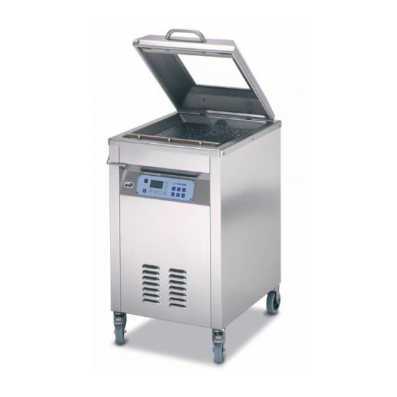
Description Description Design of the machine 2.1.1 Front view Fig. 24: Front view Handle Chamber lid Inert gas nozzle (option) Sealing bar Control terminal Swivel castor with parking brake Locking device for chamber lid Chamber Chamber lid gasket 10 Counter-pressure bar or sealing bar (option) 10.06.2014... -
Page 31: Rear View
Description Design of the machine 2.1.2 Rear view Fig. 25: Rear view (Optional) Inert gas connection Vacuum pump Power supply 10.06.2014... -
Page 32: Control Terminal
Description Control terminal Control terminal Fig. 26: Control terminal <Machine control On/Off> key Display Keys <Arrow key> Keys <1> to <6> <Function selection> key <Sealing> key <Gas flushing> key <Evacuation> key <Stop> key <Machine control • Switch machine control on and off. On/Off>... - Page 33 Description Control terminal <Sealing> key • Press and hold down: Call up "Sealing" menu. • Press briefly: Call up values for sealing. • Confirm the configuration code. • In the MPP process: select the value. <Gas flushing> key • In the MPP process: select the function. In machines with the inert gas option: •...
-
Page 34: Optional Equipment
Description Optional equipment Optional equipment 2.3.1 Pouch clamp Fig. 27: Pouch clamp The pouch clamp fixes the film pouch in place during gas flushing. 2.3.2 Suction throttle Fig. 28: Suction throttle The suction throttle is used for the continuously adjustable setting of the suction speed when packing liquids. -
Page 35: Holder For Gas Cylinder
Description Optional equipment 2.3.3 Holder for gas cylinder Fig. 29: Holder for gas cylinder This holder attaches a gas cylinder to the machine. The following gas cylinders can be attached to the machine: • Max. diameter: 160 mm • Max contents: 20 l Display The display shows different views with differing information depend- ing on the machine's phase of operation. -
Page 36: Status Display
Description Display 2.4.2 Status display Process data status display The process data status display shows information on the last pack- aging procedure. Fig. 31: Process data status display Current access right (lock closed = user; lock open = set-up personnel) Currently loaded recipe Chamber lid symbol, machine is ready. -
Page 37: Menu Display
Description Display Fig. 34: Sealing status display (050) 2.4.3 Menu display The menu display is a listing of the menus. The menu display can vary depending on the access right. The arrow on the bottom right edge indicates a continued listing. Inac- tive menu options are shown with a dash (-). -
Page 38: Diagnostic Display
Description Display Fig. 37: Function display on/off (013) Selected function Switch status Symbol of function (e.g. sealing) 2.4.5 Diagnostic display Fig. 38: Diagnostic display Diagnostic number Type of error acknowledgement Error text (in ticker) Eliminate the malfunction, see Section 8 "T ". -
Page 39: Menu Tree
Description Menu tree Menu tree Fig. 39: Menu tree Process sequence The film pouches are filled and laid in the chamber. When the cham- ber is closed, the following procedures run automatically: Evacuation Evacuation if chamber and film pouches. Gas flushing (optional) Infeed of inert gas. 10.06.2014... -
Page 40: Packaging Process
Description Process sequence Sealing • Compressed air is admitted to the sealing diaphragm. The sealing diaphragm ex- pands, pressing the sealing bar against the counter-pressure bar. • The film pouch is sealed. • The sealing bar and seal seam cool off. •... -
Page 41: Technical Specifications
Description Preset recipes Recipe Example of Evacuation Automatic Gas flush- Sealing pressure sensitivity ing pres- time sure No. 2 For moist Automatic 1.8 s products without gas flushing. No. 3 For dry Automatic 100 mbar to 1.8 s products 150 mbar with little gas flush- ing. - Page 42 Description Technical specifications Dimensions Height (a) with open chamber lid 1390 mm Height (a) with closed chamber 1020 mm Operating height approx. 900 mm Width (b) without gas mixer 570 mm Width (b) with gas mixer 720 mm Depth (c) 695 mm Effective chamber size (W/H/D) 440 mm/160 mm (optional 230...
- Page 43 Description Technical specifications Installation conditions and ambient conditions Minimum room size for machines 40 m with the gas flushing option* *For safety reasons, a minimum room size is mandatory to prevent high concentrations of gas. Inert gas without gas mixer (option) Max.
- Page 44 Description Technical specifications Noise exposure at the workplace A-weighted emission sound ≤70 dB pressure level at the workplace (DIN EN ISO 11202, accu- racy class 3) Fig. 41: Noise exposure measuring point Info The measured values of the noise emission values have been ad- justed to take extraneous and ambient noises into account.
-
Page 45: Start-Up
Check the delivery for completeness and inspect for transport damage. Inspect the crates. Inspect the machine parts. If transport damage is noted, immediately notify MULTIVAC ser- vice and report the damage. Photograph the damage. Have the photos sent to MULTIVAC service. - Page 46 Start-up Initial start-up Secure the machine on the load lifting equipment against tilting and falling over by using technically risk free transportation safety attachments. Injury hazard! Incorrect transport can cause the machine to fall or tip over. Standing in the danger zone can lead to serious injuries or even DANGER death.
-
Page 47: Filling The Vacuum Pump With Oil
Start-up Initial start-up 3.2.2 Filling the vacuum pump with oil. Checking the oil level Switch off the machine. Disconnect the machine from the mains electricity. Burn hazard! The surface of the vacuum pump can reach temperatures of over 70 °C during operation. WARNING Touching the vacuum pump can lead to burns. - Page 48 Start-up Initial start-up max. min. Check the oil level on the oil sight glass. – The oil level should reach the middle of the oil sight glass. – If oil level is under the MIN mark, add oil. With an internal vacuum pump fasten the safety guard. Adding oil Fig.
- Page 49 Start-up Initial start-up Burn hazard! The surface of the vacuum pump can reach temperatures of over 70 °C during operation. WARNING Touching the vacuum pump can lead to burns. Before performing any work on the vacuum pump: Allow the vacuum pump to cool down. Wear personal protective equipment.
-
Page 50: Connecting The Power Supply
Start-up Initial start-up With an internal vacuum pump fasten the safety guard. Connect the machine to the mains electricity. Switch on the machine. Check the oil level after a couple of machine cycles. Connecting the power supply If necessary, have the mains plug fitted and the power cable at- tached to the machine by a trained and qualified electrician, see electrical circuit diagram. -
Page 51: Attach The Gas Cylinder To The Machine
Start-up Connecting the power supply Close and press down the chamber lid. Observe the pressure shown in the display. – Chamber lid is suctioned and the pressure falls: The vac- uum pump is rotating in the correct direction. – Chamber lid is not suctioned within a maximum of 10 s and the pressure does not fall: The vacuum pump is rotating in the wrong direction. - Page 52 Start-up Attach the gas cylinder to the machine Place the gas cylinder on the holder. Push the gas cylinder so that it touches the machine. Fasten the chain around the gas cylinder. Tension the chain so that the gas cylinder is well fastened. Insert the chain.
-
Page 53: Connecting Inert Gas
Start-up Connecting inert gas Connecting inert gas Danger of explosion! Gas mixtures with oxygen proportions over 21% are explosive. A gas mixture with an oxygen proportion over 21 % can cause an DANGER explosion and fire if it comes in contact with heat, oil or grease. Do NOT use a gas mixture with an oxygen proportion of over 21%. -
Page 54: Operation
Operation Operation Switching on the machine Open all stop valves in the supply lines. If available, switch on the main switch. Switch on the display with the <control on/off> key. – The machine control performs a self-test. – The software version of the machine control briefly appears in the display. - Page 55 Operation Packing products Fill the film pouch. Insert film pouch. – The opening of the film pouch extends 2 to 3 cm beyond the sealing. If necessary, use filling plates. – The pouch neck should be located at the centre of the pouch height x.
- Page 56 Operation Packing products Pull the pouch neck flat on the sealing bar. – The pouch neck lies on the sealing bar without creases. NOTICE Danger of material damage! Penetration by foreign matter (e.g. liquids, product residue, foreign bodies) will damage the vacuum pump. Damage can cause faults in the machine, which in turn can result in reject packs.
-
Page 57: Opening And Closing Menus
Operation Packing products Info Visually inspect the packs on a regular basis while the machine is running. Depending on product and pack it may be necessary to carry out additional and considerably more complex test proce- dures. This is the responsibility of the operating company,. If necessary, adapt the settings to the product. -
Page 58: Selecting And Resetting Access Rights
Operation Changing values Set the value with the <arrow> keys. – The set value is adopted. To exit the parameter, press the <Function selection> key. Selecting and resetting access rights 4.6.1 Selecting access authorisations Call up "User" menu. Select Authorisation. Enter the password with the keys <1>... -
Page 59: Language Selection
Operation Selecting and resetting access rights Select Reset PIN. Enter Super-PIN, see supplementary sheet "Super-PIN". – The reset password for the authorisation access Creator ap- pears. – The status display appears. Language selection 4.7.1 Selecting the language via menu Call up "User" menu. Select Language. -
Page 60: Load Factory Settings
Operation Working with recipes Loading through the “load recipe” menu Call up "Load recipe" menu. Select the desired recipe with the <arrow> keys. Press the <Function selection> key. – The selected recipe is loaded. 4.8.2 Load factory settings Info Factory settings cannot be overwritten or deleted. Call up "Recipe loading"... -
Page 61: Select And Set Process
Operation Working with recipes Call up "Recipe, deleting" menu. Select the recipe to be deleted with the <arrow> keys. Press the <Function selection> key. – The message “completed” appears. – The recipe has been deleted. Select and set process 4.9.1 Set standard process Press <Evacuation>... -
Page 62: Setting The Mhp Process
Operation Select and set process Select MCV process. Set MCV threshold. Set MCV duration. Call up the "gas flushing" menu (Optional). Switch off Gas flushing On/Off. Call up the "sealing" menu. Switch off Sealing On/Off. 4.9.3 Setting the MHP process Press <Evacuation>... -
Page 63: Set Mrp Process
Operation Select and set process Select the desired function with the <Gas flushing> key and the <Arrow> keys. Set the value with the <Sealing> key and the <Arrow> keys. Scroll through the list using the <Evacuation> key and the <Ar- row>... -
Page 64: Entering Basic Settings
Operation Setting the sealing Call up the "basic settings" menu. Set Fill diaphragm. – Compressed air is admitted to the sealing diaphragm; this way the sealing bar is pressed against the counter-pressure bar. – If the chosen value is too low, the necessary sealing pressure is not reached and the seal seam can be unsatisfactory. -
Page 65: Display Hours Of Operation
Operation Display production data 4.13.2 Display hours of operation Display machine's hours of operation Call up the "Operating data" menu. Call up "Hours of operation" menu. Select Hours of operation. Display vacuum pump's hours of operation Call up the "Operating data" menu. Call up "Hours of operation"... -
Page 66: Reset Machine Control
Operation Reset machine control 4.15 Reset machine control Info Reset machine control in the following situations: • Creating the condition as supplied to the customer of the ma- chine. • If the configuration code was incorrectly entered. • Delete the entire memory. •... -
Page 67: Setting The Suction Speed
Operation Setting the suction speed 4.16 Setting the suction speed Setting the suction speed on the suction throttle. Turn the suction throttle anticlockwise. – The suction speed increases. Turn the suction throttle clockwise. – The suction speed decreases. Info Determine the correct suction speed through trial and error. 10.06.2014... -
Page 68: Adjustment Work And Setup
Adjustment work and setup Adjustment work and setup Setting the pressure regulators Fig. 43: Pressure regulator Sealing pressure regulator Switch off the machine. Disconnect the machine from the mains electricity. Remove the safety guard on the back of the machine. Set the operating pressure for sealing, see Section 5.1.1 "S ETTING ". -
Page 69: Insert And Remove The Sloping Insert
Adjustment work and setup Insert and remove the sloping insert Insert and remove the sloping insert If necessary, use filling plates for the desired incline. Hook the sloping insert on the screws of the sealing bar. Attach the support angle to the sloping insert at the required posi- tion. -
Page 70: Cleaning
In addition, the machine may be damaged. Assign only properly instructed and qualified personnel. Information on qualifica- tion and training can be obtained from MULTIVAC Service. The ability to handle materials effectively and efficiently depends on: • Using the proper dosage of care products. -
Page 71: Parameters For Pre-Rinsing And After-Rinsing Water
Cleaning Notes on cleaning NOTICE Danger of material damage! Acidic cleansers are caustic. These can cause plastics to become brittle and age prematurely. Do NOT shorten the cleaning intervals for acidic cleaning and disinfection. NOTICE Danger of material damage! Inappropriate work on anodized aluminium parts causes a damag- ing of the anodized coating. -
Page 72: Use With Disinfectant
Cleaning Notes on cleaning • For type of cleander refer to the "Care products table". • The quantity of cleanser is not the decisive factor for successful cleaning. – Applying amounts in excess of the proper dosage does not im- prove or accelerate cleaning efficiency, but only hinders the re- quired rinsing off of the cleanser. -
Page 73: Corrosion Protection And Lubrication
Cleaning Notes on cleaning 6.1.7 Corrosion protection and lubrication Health hazard! Excess lubricants can accumulate at lubrication points. Excess grease has no lubricating function; however, it can breed WARNING micro-organisms and contaminate the product. Check the lubricating points regularly for the accumulation of excess lubricants. -
Page 74: Cleaning The Machine
Cleaning Cleaning the machine Cleaning the machine Info • The recommended daily cleaning tasks recommended here must be supplemented by the intensive cleaning procedure according to the degree of dirt. • Cleaning personnel must be instructed for the cleaning work by the operating company. - Page 75 Cleaning Cleaning the machine Perform manual cleaning with the cleaning solution and a soft cloth. Wait until the contact time has elapsed (see instructions of cleanser manufacturer). If necessary, remove stubborn dirt and stains with a soft brush. Wipe with new cloth and water of drinking quality. Inspect for dirt and cleanser residues.
-
Page 76: Perform Intermediate Disinfection
Cleaning Cleaning the machine 6.2.2 Perform intermediate disinfection Info • Intermediate disinfection is a disinfection procedure during op- eration (e.g. after or immediately before short breaks) to reduce the growth of microorganisms. Quick disinfection is used for this. • The sequence of the described tasks is to be followed exactly. •... - Page 77 Cleaning Cleaning the machine Switch off the machine. Disconnect the machine from the mains electricity. Cover the mains plug with waterproof plastic bags. Close all stop-cocks in the supply lines. Allow the machine and sealing bar to cool down. Wrap up the empty new film pouches and store them outside of the room in a clean and dry place during the cleaning procedure.
- Page 78 Cleaning Cleaning the machine NOTICE Danger of material damage! The Teflon tape of the sealing bar is very sensitive. Improper cleaning can damage the Teflon tape. Clean the Teflon tape only with a soft cloth. Do NOT scratch the Teflon tape. Manually clean the removed components.
- Page 79 Cleaning Cleaning the machine Clean the machine and the floor Disassemble the liquid separator. Remove the draining hose from the liquid separator. Remove the compressed air hose. Release the winged nuts and the retaining rings on the base of the liquid separator. Open the liquid separator.
- Page 80 Cleaning Cleaning the machine NOTICE Danger of material damage! Penetration by foreign matter (e.g. liquids, product residue, foreign bodies) will damage the vacuum pump. Damage can cause faults in the machine, which in turn can result in reject packs. Do NOT spray directly on the covers of the suction openings in the chamber.
- Page 81 Cleaning Cleaning the machine Dispose of plastic bags properly. For reasons of hygiene, never reuse bags. Attach or install the following components: – Sealing bar. – Filling plate. – Sloping insert with with support angle. Open all stop-cocks in the supply lines. Connect the machine to the mains electricity.
-
Page 82: Performing Intensive Cleaning
Cleaning Cleaning the machine 6.2.4 Performing intensive cleaning Info • Intensive cleaning complements daily cleaning. As part of this process additional cleaning measures are required depending on the degree of contamination of the components described in this chapter. • The intensive cleaning may only be performed by specially trained personnel. - Page 83 Cleaning Cleaning the machine Cleaning and disinfecting the removed components Take the removed components to a separate room suitable for wet cleaning. NOTICE Danger of material damage! The Teflon tape of the sealing bar is very sensitive. Improper cleaning can damage the Teflon tape. Clean the Teflon tape only with a soft cloth.
- Page 84 Cleaning Cleaning the machine Disinfect and cover sensitive components If the external vacuum pump is connected directly to the mains electricity, have the external vacuum pump disconnected from the mains electricity by a qualified electrician. Cover the mains plug with waterproof plastic bags. Burn hazard! The surface of the vacuum pump can reach temperatures of over 70 °C during operation.
- Page 85 Cleaning Cleaning the machine Release the winged nuts and the retaining rings on the base of the liquid separator. Open the liquid separator. Perform manual cleaning of the liquid separator. Perform quick disinfection of the liquid separator. Assemble the liquid separator. NOTICE Danger of material damage! Penetration by foreign matter (e.g.
- Page 86 Cleaning Cleaning the machine Clean the viewing window in the chamber lid with a soft cloth or a soft brush. Close chamber lid and lock it in place. Clean the floor with a rubber wiper. Dispose of the dirty water and waste properly. Perform low pressure cleaning of the floor.
- Page 87 Cleaning Cleaning the machine Perform quick disinfection of the inside of the housing. Do not spray directly onto cables, contacts and electrical com- ponents. Fasten the safety guard. Disinfect the machine and the floor Perform low pressure disinfection of the floor. Open the chamber lid.
- Page 88 Cleaning Cleaning the machine Smooth out chamber lid gasket. Attach or install the following components: – Sealing bar. – Filling plate. – Sloping insert with with support angle. Open all stop-cocks in the supply lines. Connect the machine to the mains electricity. If the external vacuum pump has its own power supply, have the external vacuum pump connected to the mains electricity by a qualified electrician.
-
Page 89: Care Products Table
Cleaning Cleaning the machine Clean the cleaning devices (e.g. rubber wipers, brushes). Place cleaning devices in disinfectant solution. Unpack the film pouches and lay them ready. Switch on the machine. Close and press down the chamber lid. Observe the pressure shown in the display. - Page 90 Cleaning Care products table Type Manufacturer Designation Diversey USA Cleansers (CIP cleaning), Diversey Europe Acigel acidic Diversey USA JD Acifoam VF10 Disinfectants Ecolab Europa P3-topax 91 P3-topax 990 Ecolab USA Ster-Bac Diversey Europe JD Divosan extra VT55 JD Suredis VT1 Diversey USA JD Divosan extra VT55 JD Suredis VT1...
-
Page 91: Maintenance
Maintenance Maintenance Dangerous voltage! Switching off the machine does not rid it of electrical current. Touching electrically charged components can cause serious or DANGER even fatal injuries. Before performing any cleaning or service work: Disconnect the machine's power supply from the mains electric- ity. -
Page 92: Maintenance Recommendation
Maintenance Maintenance schedule Page Complet External vacuum pump Checking oil level, topping up Basic setting Checking, adjusting Every 50 operating hours or weekly Page Complet Entire machine Acidic cleaning and disinfection Connections Visual inspection Internal vacuum pump Visual inspection External vacuum pump Visual inspection Vacuum system Check... -
Page 93: Entire Machine - Perform Intermediate Disinfection
Maintenance Maintenance recommendation 7.2.2 Entire machine - Perform intermediate disinfection Perform intermediate disinfection regularly during operation (e.g. before or immediately after short breaks), see Section 6 "C LEAN- ". 7.2.3 Entire machine - Alkaline cleaning and disinfection See company cleaning guidelines. See the cleaning measures specified by the manufacturer, see Section 6 "C ". -
Page 94: Sealing Bars - Visual Inspection
Maintenance Maintenance recommendation Have the chamber lid gasket replaced by the MULTIVAC service department if necessary. 7.2.9 Sealing bars - Visual inspection Check sealing bar for damage. If necessary, replace the sealing bar, see Section 7.7 "R EPLACE ". THE SEALING BAR 7.2.10 Connections - Visual inspection... -
Page 95: Internal Vacuum Pump - Visual Inspection
Maintenance Maintenance recommendation If water is present in the oil, notify MULTIVAC Service. If necessary, fill with oil; see the manual of the pump manufac- turer. Have the vacuum pump connected to the mains electricity by a qualified electrician. 7.2.13 Internal vacuum pump - Visual inspection Switch off the machine. -
Page 96: Vacuum Pump Type Mrp60 - Oil Change
Have MULTIVAC Service change the oil and oil filter. 7.2.18 Vacuum pump type R5-RAxxx - Exchanging the air de-oiling element Have the air de-oiling element changed by the MULTIVAC service department. 7.2.19 Vacuum sensor - Exchanging the filter Exchanging the vacuum sensor filter, see Section 7.6 "E XCHANG- ". -
Page 97: Entire Machine - Check The Age
Close the filter housing with the clamp locks. 7.2.23 Entire machine - Check the age Read the year of manufacture on the type plate. If the machine is older than 19 years: Shut down the machine. Have the safety functions checked by MULTIVAC Service. 10.06.2014... -
Page 98: Change The Oil In The Vacuum Pump Mrp60
Maintenance Change the oil in the vacuum pump MRP60 Change the oil in the vacuum pump MRP60 7.3.1 Drain oil Fig. 44: Design of vacuum pump Screw plug of fill opening Oil sight glass Screw plug of drain opening Switch off the machine. Disconnect the machine from the mains electricity. -
Page 99: Add Oil To The Vacuum Pump
Maintenance Change the oil in the vacuum pump MRP60 Screw in the screw plug. Dispose of old oil properly. Fill the vacuum pump with new oil, see Section 7.3.2 "A DD OIL TO ". THE VACUUM PUMP Fasten the safety guard. 7.3.2 Add oil to the vacuum pump Adding oil to the... -
Page 100: Change The Air De-Oiling Element Mrp60
Maintenance Change the oil in the vacuum pump MRP60 Burn hazard! The surface of the vacuum pump can reach temperatures of over 70 °C during operation. WARNING Touching the vacuum pump can lead to burns. Before performing any work on the vacuum pump: Allow the vacuum pump to cool down. - Page 101 Maintenance Change the air de-oiling element MRP60 Burn hazard! The surface of the vacuum pump can reach temperatures of over 70 °C during operation. WARNING Touching the vacuum pump can lead to burns. Before performing any work on the vacuum pump: Allow the vacuum pump to cool down.
- Page 102 Maintenance Change the air de-oiling element MRP60 Pull out the air de-oiling element. Insert a new air de-oiling element. Make sure the position of the air de-oiling element is correct. Arrow points downwards. Fasten the cover with the screws. 10.06.2014...
-
Page 103: Performing The Vacuum Test
Maintenance Change the air de-oiling element MRP60 Fasten the safety guard on the back of the machine. Performing the vacuum test Call up the "Service" menu. Call up the "test" menu. Select Vacuum test. Switch on the vacuum test. Return to the status display. Close and press down the chamber lid. -
Page 104: Exchanging The Vacuum Sensor Filter
Maintenance Exchanging the vacuum sensor filter Exchanging the vacuum sensor filter Fig. 46: Filter in measuring line of vacuum sensor Clamp Filter Switch off the machine. Disconnect the machine from the mains electricity. Remove safety guard. Release the clamp in front of and after the filter. Replace the filter. -
Page 105: Install The Sealing Bar
Maintenance Replace the sealing bar 7.7.2 Install the sealing bar Disconnect the machine from the mains electricity. Install the sealing bar on the carriers. Install the sealing bar in such a way that the screws on the sealing bar point to the middle of the chamber. 10.06.2014... -
Page 106: Lubricant Table
Lubricant table Lubricant table Info The lubricants, which are recommended by MULTIVAC, are tailored ideally to the purpose and use. Damage to equipment or impair- ment of performance, e.g. increased wear and corrosion or similar, which is caused by use of inappropriate lubricants, is not covered by our warranty. -
Page 107: Troubleshooting
Troubleshooting Troubleshooting Injury hazard! Ignorance of proper machine handling is very dangerous. Improper handling can lead to serious injuries. WARNING For all service and repair work: Make sure you observe the safety instructions and accident prevention regulations. Disconnect the unit's power supply from the mains electricity. Only qualified electricians are permitted to work on electrical modules. - Page 108 Symptom Cause Solution • Vacuum pump does not • Notify MULTIVAC Service. switch off. • Ventilation valve does not • Notify MULTIVAC Service. open. • No inert gas available or al- • Connect inert gas or ensure most depleted.
-
Page 109: Faults Without Diagnostic Message
Troubleshooting Faults with diagnostic message Symptom Cause Solution • Vacuum pump was not trig- • Notify MULTIVAC Service. gered, overload current relay has signalled or vacuum pump is defective. • Vacuum pump is leaky. • Notify MULTIVAC Service. • Filter in the line to the vacuum •... - Page 110 • Insufficient oil quantity or oil in • Fill or replace oil. the vacuum pump is too old. • Chamber lid gasket is dam- • Notify MULTIVAC Service. aged. • Evacuation system is leaking. • Notify MULTIVAC Service. Odour or smoke.
-
Page 111: Shutdown, Transport, Storage
Shutdown, transport, storage Shutdown, transport, storage Info Observe the safety instructions, see Section 1 "S ". AFETY Shutting down the machine 9.1.1 Cleaning the machine Perform intensive cleaning of the machine, see Section 6.2 "C ". LEANING THE MACHINE 9.1.2 Closing and disconnecting supply lines Dangerous voltage! Switching off the machine does not rid it of electrical current. - Page 112 Shutdown, transport, storage Transporting the machine Shut down the machine. Use suitable and adequately sized load lifting equipment. Note here the machine dimensions and weight, see the shipping docu- ments. Set the forklift to the widest setting. Position the load lifting equipment along the longer side of the machine.
-
Page 113: Preparing The Machine For Onward Transport (I.e By Truck)
Shutdown, transport, storage Transporting the machine 9.2.2 Preparing the machine for onward transport (i.e by truck) Wear personal protective equipment. Shut down the machine. Use suitable and adequately sized load lifting equipment. Note here the machine dimensions and weight, see the shipping docu- ments. -
Page 114: Storing The Machine
Shutdown, transport, storage Transporting the machine Position the machine on the wooden base. Fasten the machine adequately to the wooden base. Wrap or cover the machine with appropriate packaging material. Position the load lifting equipment under the wooden base. While doing so establish the machine's centre of gravity. It can lie outside the centre point of the machine. - Page 115 Shutdown, transport, storage Storing the machine Observe the ambient conditions for storing the machine, see Technical specifications. Ensure that the location site is of adequate load-bearing capac- ity and keep the weight of the unit in mind, see Technical speci- fications.
-
Page 116: Disposal
Disposal Disposal 10.1 Disposing of the machine Info • Sealing bars can be reused on other machines of the same se- ries. • If disposal of the machine is not handled by the manufacturer, dispose of the machine as described below. Disconnect the machine from the mains electricity, see Section 9.1.2 "C ". -
Page 117: Disposing Of Packaging Materials
Disposal Dispose of operating materials 10.2.2 Disposing of packaging materials Info Packaging materials are resource materials that can be recycled. • Improper disposal is harmful to the environment. • Films should be collected for recycling. • Follow the disposal instructions of the packaging material manu- facturer. - Page 118 Disposal Dispose of operating materials Info Improper disposal is harmful to the environment. • Observe the safety data sheets of the cleanser and disinfectant manufacturers. • Follow the disposal instructions of the cleanser and disinfectant manufacturers. • Observe regionally applicable disposal regulations. 10.06.2014...
-
Page 119: Spare Parts
Spare parts Spare parts Fig. 47: Spare parts drawing (SAP-DIS 16000023384) Item Material number Designation Quantity and unit of measure- ment 81863140000 Profile thread (Chamber lid gasket) 2.2 m 19784322700 Tension spring (d=27 mm) 1 pc. 10.06.2014... - Page 120 Spare parts Item Material number Designation Quantity and unit of measure- ment 19784252000 Tension spring (d=20 mm) 1 pc. 81863151040 Profile thread 0.45 m 81848121000 Teflon tape 0.13 mm x 16 mm 0.45 m 11131213701 Sealing bar, complete 1 pc. 11131198110 Heating band 0.61 m...
- Page 121 Spare parts Fig. 48: Spare parts drawing Spare parts for pumps Type Voltage Frequency Material number 50 Hz - 60 Hz 105491013 • 190 V - 230 V RA0040 • 380 V - 460 V 50 Hz 106471352 • 230 V RA0040 •...
- Page 122 Spare parts Type Voltage Frequency Material number MRP60 175 V - 520 V 50 Hz - 60 Hz • Pump: 106681087 • Wearing parts set, small: 106701322 Fig. 49: Wearing parts set, small • Wearing parts set, large: 106715703 Fig. 50: Wearing parts set, large 10.06.2014...
-
Page 123: Glossary
Glossary Glossary Automatic [Parameter of the control unit] If the function Automatic is set, the machine will reach the optimum evacuation time and pressure depending on the product. The automatic evacuation is suitable for the following cases: • Achieving the best possible vacuum for long shelf life. •... - Page 124 Glossary Cycle time [Parameter of the control unit] The display contains the times of the individual procedures of the last packaging procedure. Delayed ventilation - [Parameter of the control unit] Sealing The ventilation of the chamber begins with a delay after sealing. Diagonal insert Fig.
- Page 125 Glossary Gas flushing [Optional] The film pouches are filled with inert gas. Gas flushing with inert gas has the following advantages: • It extends the shelf life of the product. • It reduces oxygen content. • It avoids putting pressure on the product. Gas flushing pressure [Optional] [Parameter of the control unit] Indicates the pressure up to which the film pouch is back filled with...
- Page 126 P2 Tolerance range for the evacuation pressure (MCV threshold) P3 Ambient pressure During the MCV (MULTIVAC Continuous Vacuum) process, a prod- uct or a pack is exposed to a vacuum for up to 20 days. The cham- ber is evacuated to the set pressure, which is then maintained for the set time.
- Page 127 Glossary p (mbar) t (s) Fig. 54: Example diagram of MHP t1 Evacuation pause t2 Evacuation time V1 Evacuation pressure During the MHP process, evacuation takes place in several steps. The air is suctioned out for a set time (evacuation time); a set pause in suctioning (evacuation pause) follows.
- Page 128 P3 Gas flushing pressure in steps 5 and 8 P4 Ambient pressure During the MPP (MULTIVAC Programmed Processing) process the progression of the evacuation curve and gas flushing curve can be freely selected. The entire procedure can be comprised of up to 30 steps, with each step assigned a function and a value.
- Page 129 P1 Evacuation pressure P2 Gas flushing pressure P3 Ambient pressure During the MRP (MULTIVAC Repeated Processing) process, evacuation and gas flushing takes place alternately over several cycles. The machine evacuates and flushes gas to the set pressures and repeats the procedure according to the settings.
- Page 130 Glossary Post-evacuation time [Parameter of the control unit] This time extends the evacuation process. Through this, the reached evacuation pressure is lower than the set value. This time begins, when the set pressure is reached. Suitable for damp products. Purging time, gas [Optional] [Parameter of the control unit] flushing During this time the vacuum valve and gas valve are opened simul-...
- Page 131 Glossary standard Fig. 59: Example diagram of standard process P1 Evacuation pressure P2 Gas flushing pressure P3 Ambient pressure During the standard process, air is suctioned out until the set pres- sure is reached. Afterwards, gas is flushed at the set pressure (op- tion).
- Page 132 Glossary Ventilation pulse pres- [Parameter of the control unit] sure During the closing of the sealing unit, the chamber is ventilated until this pressure value is reached. As a result, the film pouch settles better on the product. Fig. 51: Sequence diagram packaging procedure with ventilation pulse t1 Start evacuation procedure t2 The evacuation pressure is reached, the sealing unit closes, start ventilation...
-
Page 133: Index
Index Index Access authorisations, selecting 58 Daily cleaning 76 Access right 58 Daily disinfection 76 Access right, resetting 58 Danger zones 20 Access rights 38, 39 Delayed ventilation - sealing 124 Access, blocking 58 Delivery, checking 45 Adjustment work 68 Depth 42 Against regulations 14 Diagnostic display 38... - Page 134 Index fault 109 Load recipe 59 Faults 107 Load recipe quickly 59 Fill diaphragm 124 Lock 36 Fill opening, oil 48, 98, 99 Locking device, chamber lid 30 Film, disposal 117 Login 58 Front view 30 Low pressure cleaning 74 Low pressure disinfection 75 Low-pressure test 19 Gas cylinder 35...
- Page 135 Index Nominal current 41 Nominal power 41 Rear view 31 Nominal suction capacity 43 Reasonably foreseeable incorrect use 14 Non-ionising radiation 14 Recipe 59, 130 Number of cycles 129 Recipe keys 59 Recipe, deleting 60 Recipe, saving 60 Oil disposal 116 Recipes 40 Oil level, checking 47 Relative air humidity 42...
- Page 136 Index Sloping insert, inserting 69 Total cycles 64, 131 Sloping insert, removing 69 Transport 111 Software version 35 Transport damage 45 Spacer plate 130 Transport equipment 111 Spare parts 119 Troubleshooting 107 Spare parts for pumps 121 Type designation of machine control 35 Stacking test 19 Standard 131 Standard process 40...
-
Page 137: Multivac Branch Offices
MULTIVAC branch offices MULTIVAC branch offices GERMANY MULTIVAC Sepp Haggenmüller GmbH & Co. KG Tel.: +49 83 34 601 0 Fax:+49 83 34 601 199 multivac@multivac.de www.multivac.com SWITZERLAND MULTIVAC EXPORT AG Tel.: +41 41 785 65 65 Fax:+41 41 785 65 10 meag@multivac.ch... - Page 138 INDIA IRELAND ISRAEL MULTIVAC Laraon India Pri- MULTIVAC Ireland Ltd. MULTIVAC B.P.S. Ltd. vate Limited Tel.: +353 (0) 1 4133200 Tel.: +972 46 344 68 1 Tel.: +91 12 446 10 000 Fax:+353 (0) 1 4133205...
- Page 139 MULTIVAC branch offices AUSTRIA POLAND PORTUGAL MULTIVAC Vertriebsgesell- MULTIVAC Sp. z o. o. Multi Vacuo - Sistemas de Embal- schaft mbH Tel.: +48 81 746 67 00 agens Lda. Tel.: +43 (0)1 698 1300 Fax:+48 81 746 67 01 Tel.: +351 21 41 95 541 Fax:+43 (0)1 698 1300-99 mupl@multivac.pl...
- Page 140 MULTIVAC branch offices HUNGARY UNITED ARAB EMIRATES MULTIVAC Hungária Kft. MULTIVAC, Inc. MULTIVAC Middle East (FZE), Tel.: +36 23 500 28 7 Tel.: +800 877 5200 Amir Sotoudeh Fax:+36 23 500 28 8 Tel.: +1 816 891 0555 Tel.: +971 4 299 1980 info@hu.multivac.com...
Need help?
Do you have a question about the C300 and is the answer not in the manual?
Questions and answers