Table of Contents
Advertisement
Quick Links
Advertisement
Table of Contents

Related Manuals for TransAct Ithaca 800 Series


Summary of Contents for TransAct Ithaca 800 Series
- Page 1 800 Series Models 850, 860 PN: 85-03670 Rev C Mar-03...
- Page 3 Change History Rev A Initial Release Rev B Page 36 added Item #14 (85-04169) Rev C Updated disclaimer Mar-03 Rev C Page Confidential Information: Not for Distribution.
-
Page 4: Important
Losses that can be attributed to improper installation and working procedures are not the responsibility of TransAct Technologies Inc. No part of this manual may be used to recreate any part of the 800 Series Printer. If this manual contains any questionable information or mistakes please contact TransAct for assistance. -
Page 5: Table Of Contents
Internet Support ............................1 www.transact-tech.com..........................1 Service Information ............................2 Ithaca Product Support Procedure ......................2 Contacting TransAct’s Ithaca Facility......................3 SERIES 800 SPECIFICATIONS AND REQUIREMENTS Series 800 Model Functionality Descriptions ..................... 4 Standard Features ............................4 Optional Features ............................5 Dimensions .............................. - Page 6 Ticket Taken Sensor ..........................14 Head-Up Switch............................14 Void and Reprint (Model 860 only)......................14 Open/Close Position Sensor/Audible Alarm.................... 15 Printer Status LED ........................... 16 ELECTRICAL CONNECTIONS Serial Communications Interface PCB ..................... 17 Default Communication Settings ......................18 Bezel Lamp Connector ..........................18 Printer Block Diagram..........................
- Page 7 Series 800 Maintenance Manual Table of Contents Figures Figure 1 800 Series Printer Component Overview ......................4 Figure 2 Series 800 Printer: Dimensions ........................... 6 Figure 3 Design Envelope: Ticket Clearance ........................9 Figure 4 Location of Black Dot/Top of Form Indicator on Back of Ticket................10 Figure 5 Ticket Stack Orientation ............................
-
Page 9: Series 800 General Information
12 months, may be purchased separately. For more information concerning the warranty options, please contact the Sales Department at TransAct’s Ithaca facility. You are responsible for insuring any product returned for service, and you assume the risk of loss during shipment to Ithaca C.O.D. packages are not accepted and warranty repairs are subject to the terms and conditions as stated on the Ithaca warranty policy (packed with each new printer). -
Page 10: Service Information
General Information Service Information TransAct Technologies Incorporated has a full service organization to meet your printer service and repair requirements. If your printer needs service, please contact your service provider first. If any problems still persist, you can directly contact the Ithaca facility’s Technical Support Department at (607) 257-8901 or (877) 7ithaca for a return authorization. -
Page 11: Contacting Transact's Ithaca Facility
General Information Contacting TransAct’s Ithaca Facility Contact TransAct’s Ithaca facility for general information about integrating 800 Series printers with your system. The Sales and Technical Support Departments will be able to help you with most of your questions. Call the Technical Support Department to receive technical support; order documentation; receive additional information about the 800 Series;... -
Page 12: Series 800 Specifications And Requirements
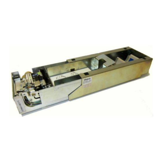
Series 800 Maintenance Manual Specifications and Requirements Series 800 Specifications and Requirements Figure 1 800 Series Printer Component Overview Printer Mechanism Printer Mechanism Assembly Printer Ticket Bucket (200, 400, 600) Outer Slide Chassis Series 800 Model Functionality Descriptions There is a specific functional difference between the Model 850 and the Model 860 printers. As an option, the Model 860 incorporates a void and reprint sensor that verifies the integrity of the barcode. -
Page 13: Optional Features
Series 800 Maintenance Manual Specifications and Requirements • Modular Interface PCB. • Audible Buzzer Optional Features • 400 and 600 count ticket trays. • Void and Reprint (Model 860 only) Mar-03 Rev C Page Confidential Information: Not for Distribution. -
Page 14: Dimensions
Series 800 Maintenance Manual Specifications and Requirements (Dimensions reflect use of 200 unit ticket bucket unless otherwise noted) Dimensions Figure 2 Series 800 Printer: Dimensions Stationery Module Size: H: 2.66" (67.6mm) W: 4.46" (113.3 mm) D: 11.25" (285.75 mm) The Series 800 is a stationery module, and is designed to work with either of the three interchangable Ticket Buckets. -
Page 15: Reliability
Series 800 Maintenance Manual Specifications and Requirements Reliability Printer Life: 20 million print lines. Mean time between failures: 45,000 hrs. @ 25% duty cycle. Printer electronics: 250,000 hrs. Printhead Life: 50Km min. Flex ribbon (sliding module): 1,500 cycles min. Power Requirements 24 Vdc ±... -
Page 16: Printing Specifications
Series 800 Maintenance Manual Specifications and Requirements Printing Specifications Print Method: Thermal Sensitive Line Dot System. Ticket Handling: Straight. Entire path is accessible. Print Speed: 125 mm/sec. (5" per sec.) max. (in text mode) Paper advance speed: 125 mm/sec. (5" per sec.) min. Resolution: 203dpi x 203dpi and 136dpi x 203dpi. -
Page 17: Ticket Specifications (Continued)
Series 800 Maintenance Manual Specifications and Requirements Ticket Specifications (continued) The 800 Series printer requires the following tickets for proper printing: Ticket Type: Kanzaki TO-381N or approved equivalent Thermal sensitive layer facing down. Thermal sensitive side to be coated for wear characteristics. Quantities Available: Fan-folded stacks of 200, 400 and 600 tickets. -
Page 18: Print Characteristics
Series 800 Maintenance Manual Specifications and Requirements Print Characteristics The statistics for the internal fonts the 800 Series Printer supports appear below. Height and width are expressed in terms of dots. Height Width Horizontal cpi Vertical cpi 16.9 12.7 10.2 Table 1 Font Statistics Black Dot Position and Presentation Scheme All graphics preprinted on the ticket must be in thermal paper compatible ink. -
Page 19: Ticket Stack Orientation
Series 800 Maintenance Manual Specifications and Requirements Ticket Stack Orientation To ensure the ticket is loaded correctly into the printer, the ticket stack must be properly loaded in the ticket box. The stack must be oriented so that the Black Dot/Top of Form mark of the tickets is on the leading edge of the ticket, not near the perforation of the next ticket. -
Page 20: Mounting Requirements
Series 800 Maintenance Manual Mounting Requirements Mounting Requirements Chassis Mounting to Final Product Bottom: 4x M4x 0.7 press nuts 4x .180" thru holes Figure 6 Outer Chassis Mounting to Final Product Page Rev C Mar-03 Confidential Information: Not for Distribution. -
Page 21: Custom Bezel Specifications And Recommendations
Series 800 Maintenance Manual Mounting Requirements Custom Bezel Specifications and Recommendations Custom Bezel to Printer Mechanism Mounting points Series 800 printers are designed to accomodate a customer supplied bezel assembly that is mounted following the hardware and mounting dimensions as listed. The following drawing shows the positioning and dimensions of the Series 800 printer’s mounting points. -
Page 22: Series 800 Printer Sensors
Series 800 Maintenance Manual Sensors Series 800 Printer Sensors The Series 800 printers use several sensors to provide feedback to the host system. All power and interface communications are handled by the Comunications PCB. Figure 8 Sensor Breakdown and Locations Paper Low Sensor A Paper Low Sensor optically senses the number of tickets remaining in the printer’s ticket bucket. -
Page 23: Open/Close Position Sensor/Audible Alarm
Series 800 Maintenance Manual Sensors Open/Close Position Sensor/Audible Alarm The printer has an OPEN/CLOSE POSITION sensor to determine if the Printer Mechanism Assembly is in the full-racked position. If the Printer Mechanism Assembly is not in the fully racked position, then the printer status LED will blink indicating the printer is not ready. -
Page 24: Printer Status Led
Series 800 Maintenance Manual Sensors Printer Status LED The printer has been outfitted with a LED indicator system that provides the condition of the printer by using a series of blinks to communicate the status of the printer. If a customer supplied Bezel is installed, the status of the Bezel will be identical to the LED The following table lists the different LED indications and provides a brief description. -
Page 25: Electrical Connections
Series 800 Maintenance Manual Electrical Connections Electrical Connections Serial Communications Interface PCB All power and communications are supplied through the Serial Communications PCB located at the rear of the printer. The interface connector is a 14 position Molex Minifit Jr®., part number 39-30-1400, and will mate with Molex part number 39-01-2140 or equivalent . -
Page 26: Default Communication Settings
8,192 bytes These communications settings may be altered only through the use of special printer configuration software. Contact TransAct for availability. Bezel Lamp Connector The bezel connector is a Molex Minifit Jr®, part number 39-01-4032 and will mate with a Molex part number 39-01-4030 or equivalent. -
Page 27: Printer Block Diagram
Series 800 Maintenance Manual Operational Procedures Printer Block Diagram C h a s s i s - I n n e r S l i d e Print M e c h a n i s m A s s e m b l y P a p e r F e e d C h a s s i s - O u t e r S l i d e M o t o r... -
Page 28: Operational Procedures
Series 800 Maintenance Manual Operational Procedures Operational Procedures Loading Tickets into Feeding Mechanism When loading new ticket stacks, be sure that the printer mechanism assembly has been unseated from the outer slide chassis’s racking retainers, and there is power to the printer. The first ticket of the stack must be inserted into the printer by hand. -
Page 29: Removing Loaded Tickets
Series 800 Maintenance Manual Operational Procedures Slide the printer mechanism assembly back into the closed position, making sure that the assembly’s slide plungers snap into the racking retainers within the outer slide chassis. The printer is ready to receive information. Removing Loaded Tickets The Series 800 printers have two ways to remove unused tickets from the printer mechanism assembly. -
Page 30: Figure 15 Feed Switch And Led Indicator Location
Series 800 Maintenance Manual Operational Procedures Figure 15 Feed Switch and LED indicator Location Unloading Tickets from the Printer using the feed button Pull printer mechanism assembly out of the slide chassis until it stops in the open position. Separate ticket currently loaded in the platen assembly from the ticket bundle. Press the feed button to eject the ticket. -
Page 31: Cleaning The Print Head
The cleaning card will automatically be drawn into the feed path. Repeat process if necessary. Properly dispose of used cleaning card. Cleaning cards are available through TransAct or can also be purchased direct from Enefco International Ltd. at (888) 578-0141. Description: Part Number: 2.5"... -
Page 32: Chapter 7: Assembly/Disassembly
Due to this your unit’s design may vary from the specifications and options shown here. All of the content of this manual, is reflective of the TransAct Series 800 Printer including all of its available options. TransAct does not assume support responsibility for parts other than what is shown in this manual. -
Page 33: Racking/Unracking The Printer Mechanism Assembly
Series 800 Maintenance Manual Assembly/Disassembly Racking/Unracking the Printer Mechanism Assembly All Series 800 printers use a slider/detent system with springs to retain the Printer Mechanism Assembly from accidentally being separated from the Outer Chassis. The Series 800 is opened for service by simply pulling the Printer Mechanism Assembly out of the Outer Chassis as you would a filing cabinet. -
Page 34: Removing The Ticket Tray From The Main Printer Assembly
Series 800 Maintenance Manual Assembly/Disassembly Removing the Ticket Tray from the Main Printer Assembly Figure 18: Removing Ticket Tray Lift on back of Ticket Tray to remove it. It will unsnap from the printer without the need for tools. To re-install the Ticket Tray, insert the two front tabs of the Ticket Tray into the provided slots, and rotate the rear end of the tray, and re-sanp it back into place. -
Page 35: Remove Pcb Cover Plate From Printer Mechanism Assembly
Series 800 Maintenance Manual Assembly/Disassembly Remove PCB Cover Plate from Printer Mechanism Assembly Figure 19; Remove PCB Cover Plate Loosen completely the four (4) thumbscrews that retain the PCB Cover Plate. Lift the PCB Cover Plate away from the Printer Mechanism Assembly. Unplug the Ticket Low Sensor Assembly form the Main Controller PCB. -
Page 36: Remove Print Mechanism From Printer Mechanism Assembly
Series 800 Maintenance Manual Assembly/Disassembly Remove Print Mechanism from Printer Mechanism Assembly Figure 20: Remove Print Mechanism Unplug all Print Mechanism connectors from the Controller PCB Assembly. Firmly grasp the sides of the Print Mechanism, and rotate it towards the rear of the Print Mechanism Assembly. -
Page 37: Remove Controller Pcb Assembly From Printer Mechanism Assembly
Series 800 Maintenance Manual Assembly/Disassembly Remove Controller PCB Assembly from Printer Mechanism Assembly Figure 21: Removing Controller PCB Assembly Remove/install Controller PCB Assembly by unsnapping/snapping it from/onto the four (4) stand-offs that hold the board in position. Unplug Bezel Harness from Controller PCB Assembly. Mar-03 Rev C Page... -
Page 38: Remove Interface Pcb Assembly From Outer Slide Chassis
Series 800 Maintenance Manual Assembly/Disassembly Remove Interface PCB Assembly from Outer Slide Chassis Figure 22: Remove Interface PCB Assembly Remove Interface PCB Assembly from Outer Slide Chassis by removing two (2) M4 Screws with a #2 Phillips Head Screwdriver. Page Rev C Mar-03 Confidential Information: Not for Distribution. -
Page 39: Chapter 8: Parts Lists
Series 800 Maintenance Manual Assembly/Disassembly Chapter 8: Parts Lists Complete 850 Assembly Description (standard parts) Part No. (History) Print Mech Assy-STD RM034647-01 Print Mech Assy-RAP R85-00525 Assy-Serial Outer Slide R85-00524 Assy-Netplex Outer Slide RM034648-01 Tray-200 Ticket w/Label 85-03672 Tray-400 Ticket w/Label 85-03673 Tray-600 Ticket w/Label 85-03674... - Page 40 Series 800 Maintenance Manual Assembly/Disassembly Print Mechanism Assembly Description (standard parts) Part No. (History) Bracket-Front Lower-Paper M068278-02 Chassis-Printhead M068266-02 Cover & Platen Assembly RM034656-01 Gear-54/16 Tooth M068272-01 Guide-Printhead Spring M068271-01 Guide-Rear-Paper M068312-02 Harness Assy-Motor and Switch RM034654-01 Printhead-Thermal M067832-03 Ring-Retaining 520-9800002 Screw-2-28X7/16 Ph Phl Selftap M067908-01...
- Page 41 Series 800 Maintenance Manual Assembly/Disassembly Outer Slide Assembly Description (standard parts) Part No. (History) Assy-RS232 Interface PCB 85-03526 Assy-Netplex Interface PCB E030062-01** Chassis-Outer M068258-01 Screw-M4X0.7X6 Ph M066711-04FLRX Guide-Slide Rail M068275-01 Nut-M3 Hex w/Lockwasher 98-0621 Assy-Harness 30 Pos. 85-03510 Assy-Interface Cable (Netplex) M034655-01** * Not available as a spare part ** Sales of these parts restricted to approved customers only...
- Page 42 Series 800 Maintenance Manual Assembly/Disassembly Inner Slide Assembly Description (standard parts) Part No. (History) Assy-Controller PCB E030063-01 Chassis-Inner Slide M068259-02 Harness Assy-3/3 Straight M034653-01 Assy-PCB Cover Plate R85-03677 Plunger-Slide M068262-01 Spring-Compression-Plunger 85-03552 Shield-Plunger Guide 85-03532 Stop-Slide Block M068274-01 Screw-6-18X1/4 Ph Selftap M067883-03 Strap-Ground Slide M068323-01...
- Page 43 Series 800 Maintenance Manual Assembly/Disassembly PCB Cover Plate Assembly Description (standard parts) Part No. (History) Plate-PCB Cover M068261-01 Sensor Assembly-Paper Low RM034658-01 Nest-Sensor 85-03531 Screw-M3X0.5X10MM Ph Phl Sems M067831-02* Window-LED M068326-01 Ring-.187 dia. Push on Retaining M068334-01 Button-Dark Gray M067906-01 Mount-Switch Button M068327-01 Spring-Compression...
- Page 44 Series 800 Maintenance Manual Assembly/Disassembly Cover and Platen Assembly Description (standard parts) Part No. (History) Nut-M3 Hex 98-0621* Label-Press To Open 85-00549* Retainer-‘E’ Ring 520-9800003 Label-Green Dot 85-00550* Assy-Platen and Gear RM034651-01 Assy-Top of Form Sensor RM034657-01 Assy-Latch Shaft M034660-01 Bearing-platen M068263-01 Bracket-Pivot...
- Page 45 Series 800 Maintenance Manual Assembly/Disassembly Read After Print (RAP) Option Description (standard parts) Part No. (History) Assy-RAP Sensor/Tip R85-03499 Assy-RAP PCB Harness R85-00533 Screw-M3X16MM 98-2034 Spring-RAP M068333-02 Nut-M3 Hex w/Lockwasher 98-0621 * Not available as a spare part Mar-03 Rev C Page Confidential Information: Not for Distribution.
Need help?
Do you have a question about the Ithaca 800 Series and is the answer not in the manual?
Questions and answers