Table of Contents
Advertisement
Quick Links
Advertisement
Table of Contents

Related Manuals for TransAct Epic 430


Summary of Contents for TransAct Epic 430
-
Page 1: Maintenance Manual
Maintenance Manual P/N 43-06955 April 2013... - Page 2 This page intentionally left blank...
-
Page 3: Change History
4/13 Federal Communications Commission Radio Frequency Interference Statement Epic 430 Printer complies with the limits for a Class A computing device in accordance with the specifications in Part 15 of FCC rules. These regulations are designed to minimize radio frequency interference during installation;... -
Page 4: Regulatory Compliance
Epic 430 Printer does not exceed Class A limits for radio noise emissions from digital apparatus set out in the Radio Interference Regulations of the Canadian Department of Communications. Regulatory Compliance FCC Class A and B CE Mark UL 1950, TUV... -
Page 5: Disclaimer
TransAct Technologies, Inc. ("TransAct"). This document is the property of and contains information that is both confidential and proprietary to TransAct. Recipient shall not disclose any portion of this document to any third party. TRANSACT DOES NOT ASSUME ANY LIABILITY FOR DAMAGES... -
Page 6: Table Of Contents
Disclaimer ...................... iii Copyright ....................... iii Trademarks ....................iii Table of Contents ................... iv Figures ......................vii Tables ......................vii Introducing your Epic 430 Printer ....1 ® About your TransAct Epic 430 Printer ............3 Who Should Read This Guide? ............... 4 What Is Included in This Guide? .............. - Page 7 Necessary Tools ..................51 Disconnecting the Power and Communications Cables ......51 Main Printer Components ................. 52 Principal Subassemblies for the Epic 430™ Printer........53 Assembling the Printer Mechanism ............58 Assembling Main Printer Components ............65 Parts List ..........69 Modular Configuration ...................
- Page 8 Print Mechanism ................... 71 Base Assembly ..................... 73 Paper Holder Assembly................. 74 Remote Base Assembly ................75 Spindle Assembly ..................76 Transport Assembly ..................77 0ptional 80MM Paper Guide…………………………………………………………………………………………………. 78 Index ............79 Page vi 43-06955 - Rev Q...
- Page 9 Figure 12. Communication PCB Location and Connector Info....... 47 Figure 13. Power and Communications Cable Connections......51 Figure 14. Exploded View of Main Assemblies for Epic 430 Printer....52 Figure 15. Right Side Frame Assembly............53 Figure 16.
-
Page 11: Introducing Your Epic 430 Printer
Chapter 1 Introducing your Epic 430 Printer 43-06955 - Rev Q Page 1... - Page 12 This page intentionally left blank Page 2 43-06955 - Rev Q...
-
Page 13: About Your Transact ® Epic 430 Tm Printer
It builds upon the architecture of TransAct’s proven thermal printers, together with a host of features specifically designed to improve the performance of your receipt printing applications, including: ... -
Page 14: Who Should Read This Guide
Listing of available spare parts. ® We want you to have a trouble-free implementation with your TransAct printer. For any issues not covered in this guide, quality technical support is available on-line at www.transact-tech.com, or by telephone or fax – consult the following pages for more details about our support services. -
Page 15: Technical And Sales Support
TransAct printer. Click on Ithaca link and then the Technical Support link to find support information for your Epic 430 printer. Our on-line support site also includes a convenient e-mail assistance request form, where you can submit support requests 24 hours a day, and receive a return contact from a TransAct support technician during regular business hours. -
Page 16: Return Materials Authorization And Return Policies
Return Materials Authorization and Return Policies If a support technician determines that the printer should be serviced at a TransAct facility, and you want to return the printer for repair, we will issue you the Returned Materials Authorization (RMA) number that is required before returning the printer. -
Page 17: Contact Information
About Your Epic 430 Printer Contact Information TransAct Technologies Incorporated Ithaca Facility 20 Bomax Drive Ithaca, NY 14850 USA TransAct Technologies World Gaming Headquarters & Western Regional Repair Center 6700 Paradise Road Suite D Las Vegas, NV 89119 USA Telephone 877.7ithaca or 607.257.8901... -
Page 19: Epic 430 Specifications And Requirements
Chapter 2 Epic 430 Specifications and Requirements 43-06955 - Rev Q Page 9... - Page 20 This page intentionally left blank Page 10 43-06955 - Rev Q...
-
Page 21: Epic 430 Tm Specifications And Requirements
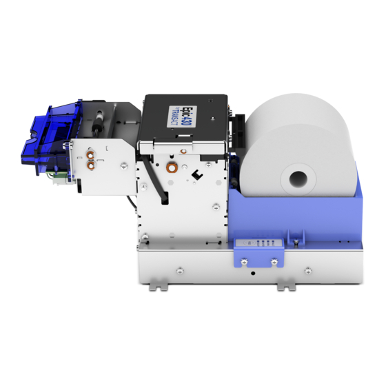
Epic 430 Specifications and Requirements Figure 1. Epic 430 Printer. Standard Features The following features are standard for Epic 430 printers: Modular design, with electronics base assembly capable of being mounted remotely up to two feet from the printer mechanism. -
Page 22: Optional Features
Specifications and Requirements 4 MB minimum flash memory and 8 MB RAM Ithaca command set emulation Power: 24 VDC, 3 amps max. Power Connector: 4 pin Molex Paper Out, Paper Cover-Open, Top-Of-Form, Anti-Jam, Transport Ticket Taken and Head Temperature sensors ... -
Page 23: General Specifications
Specifications and Requirements General Specifications 5.25” (134mm) 11.76” (299mm) 5.23” (133mm) Figure 2. Epic 430 Dimensions. Printer Dimensions Max Dimensions Dimensions in 5.23 11.76 5.25 inches Dimensions in millimeters (fully assembled as single unit) Weight Approximate weight 4.7 lb Interface Type... -
Page 24: Printer Type
Specifications and Requirements Printer Type Fixed 80 mm linear thermal head. Figure 3. Temperature and Humidity Ranges. Printer Environmental Conditions Operating Temperature Range: 5º - 50ºC (41ºF - 122ºF) Shipping/Storage Temperature Range: –10º - 50ºC (14ºF - 122ºF) Operating Humidity Range: 10% - 90% non-condensing Shipping/Storage Humidity Range: 10% - 90% non-condensing... -
Page 25: Test Standards
Specifications and Requirements Test Standards CE MARK (1998) FCC CLASS B EN60950-1 IEC 60950 (1991) Second Edition with Amendments 1,2,3,4 ROHS/WEEE Accoustic Noise: 58 dBA 43-06955 - Rev Q Page 15... -
Page 26: Printing Specifications
A receipt paper out sensor is provided as a standard feature, which senses when approximately 1 inch (length) of paper is left on the paper roll. Auto Cutter Position ® A full cut auto-cutter is a standard feature with all TransAct Epic 430 printers. Cutter type... -
Page 27: Communications Interface
Specifications and Requirements Communications Interface RS-232 Serial Interface Serial Port Features The serial port features are as follows: Baud Rates 300, 600, 1200, 2400, 4800, 9600, 19.2K, 38.4K, and 57.6K Bit Patterns 8-bit no parity; 8-bit odd; 8-bit even; 7-bit no parity; 7-bit odd; 7-bit even Flow Control DTR and XON/XOFF... -
Page 28: Power Input Connector Interface
Note: The standard USB interface does not have enough power to run the printer. It is not possible to power the printer with the USB cable alone. Power Input Connector Interface The power input connector for the Epic 430 printer uses a Molex 4-pin interface, with pin functions are as shown. -
Page 29: Operational Procedures
Chapter 3 Operational Procedures 43-06955 - Rev Q Page 19... - Page 30 This page intentionally left blank Page 20 43-06955 - Rev Q...
-
Page 31: How To Operate The Epic 430
Operational Procedures How to Operate the Epic 430 Printer User Interface Your Epic 430 printer contains two buttons and four (LED) indicator lights. Indicator Lights (LED) The four Epic 430 indicator lights are: Ready LED Indicates printer activity and non-recoverable errors ... -
Page 32: The Test Button
Operational Procedures The TEST button The printer has a TEST button on the right side of the Electronics Base. This button will require a tool (such as a pen or paper clip) in order to activate the switch. TEST Button (inside hole) Figure 5. -
Page 33: Using Self-Test
Cleaning the drive roll may correct the problem. If this does not correct the problem, contact TransAct’s Technical Support department. Operation - Marker Calibration The printer is equipped with several sensors in the paper path, which are adjustable and will handle a wide range of paper under normal operation. - Page 34 Operational Procedures Factory Test The printer is equipped with several factory test modes. These test options are only used for factory testing. Operation - Continuous Operation - Burn-in Operation - Rolling ASCII Page 24 43-06955 - Rev Q...
-
Page 35: Level 0 Diagnostics
Operational Procedures Level 0 Diagnostics Level 0 diagnostics are only and always run at power up, e.g. when power is first applied. These diagnostics perform the following tasks: Power On Basic System Integrity Vector Integrity RAM Test Flash Boot Loader Integrity Flash Firmware Integrity (NOTE: If the firmware is corrupted, the printer will remain in boot load.) USB Controller Diagnostics and verify. - Page 36 Note: In this download mode, the printer will only accept data on the RS232 serial port. A second level loader, described in more detail in the command Epic 430 OEM Integration Manual section of the , supports the USB interface.
-
Page 37: Printer Status Led's
When the printer is in Self Test Mode, the power indicator will blink slowly with a 50% duty cycle at a 2 second rate. This is very similar to TransAct Boot Load Mode, however, the red error indicator will not be present. -
Page 38: Auto Error Recovery
14 Blinks Kernel Fault 15 Blinks Auto Error Recovery The Epic 430 printer has the ability to auto recover from some internal errors. Flash Format Errors The internal flash that is used to store graphic images is formatted to assure data integrity. -
Page 39: Loading Paper
Operational Procedures Loading Paper The Epic 430 printer uses a continuous roll of POS or Lottery grade thermal Epic 430TM Specifications paper, with specifications outlined in the chapter and Requirements Paper direction Knife assembly opening Figure 6. Loading a Paper Roll. -
Page 40: Cleaning The Print Head
Operational Procedures 5. Close the cover by rotating it back into position until it securely clicks into place. Paper will feed automatically, and then print and eject a test ticket. Cleaning the Print Head Once the unit is opened, the paper path is accessible for cleaning or clearing paper. -
Page 41: Configuring Your Epic 430 Printer
Chapter 4 Configuring Your Epic 430 Printer 43-06955 - Rev Q Page 31... - Page 42 This page intentionally left blank Page 32 43-06955 - Rev Q...
-
Page 43: Configuration Mode Overview
TransAct’s remote configuration software. TransAct Technologies offers the use of a remote CONFIG program as a fast, easy way for system integrators to configure or reconfigure your Epic 430 printer. To obtain more information, or the latest version of the CONFIG program, call TransAct’s Sales Department or Technical Support. -
Page 44: Setting Up For Color Paper
It will also allow the configuration of one printer to be recorded and replicated over a number of printers. The program is available from TransAct Technical Support or by downloading it from the Internet – consult the section On-line Technical Support for further details. -
Page 45: Mounting Requirements
Chapter 5 Mounting Requirements 43-06955 - Rev Q Page 35... - Page 46 This page intentionally left blank Page 36 43-06955 - Rev Q...
-
Page 47: Mounting Requirements
Mounting Requirements Electronics Base Assembly to Final Product The following shows dimensions and locations for mounting a standard Epic printer, with attachment points shown on the Electronic Base Assembly. Bottom: 4x M4x 0.7 screws. 4x Ф.176" thru holes. Bucket mounting holes 7.827 Cover plate... -
Page 48: Remote Base Cover
Remote Base Cover The Epic 430 printer can optionally be configured for the printer mechanism to be mounted remotely from the electronics base. In such a case, a remote base cover is attached to the base of the printer mechanism. The diagram shows mounting holes and dimensions for this base cover, while the subsequent image shows this base cover attached to the printer mechanism. -
Page 49: Epic 430 Grounding
Remote Base Figure 9. Remote Base Mounted to Printer Mechanism Epic 430 Grounding Due to the modular capability of the E430 printer, special considerations should be taken to ensure the modules are commonly grounded for immunity to external electrical faults such as ESD, magnetic transients, and radio frequency interference. -
Page 50: Custom Bezel Specifications And Recommendations
(Bezel assemblies are available from TransAct as an option with your printer.) The following drawing shows the positioning and dimensions of the Epic 430 printer’s mounting points. Front: 2x M3x 0.5 screws and interface with custom bezel. -
Page 51: Printer Sensors
Chapter 6 Printer Sensors 43-06955 - Rev Q Page 41... - Page 52 This page intentionally left blank Page 42 43-06955 - Rev Q...
-
Page 53: Printer Sensors
Printer Sensors Printer Sensors The Epic 430 printer uses several sensors to provide feedback to the host system, as pictured in Figure 11. Transport Ticket Taken Sensor Top-of-Form Sensor Paper Out Sensor Paper Low Sensor Anti-Jam Sensor Cover-Open Switch (located on inner frame) Figure 11. -
Page 54: Cover-Open Switch
The length of paper remaining when paper low is sensed is dependent on the paper roll core diameter. When using the modular version of the Epic 430™ the paper low sensor will be mounted on the spindle. Anti-Jam Sensor An Anti-Jam Sensor is mounted to the knife frame, and senses the presence of a ticket immediately before and after a knife cut. -
Page 55: Electrical Connections
Chapter 7 Electrical Connections 43-06955 - Rev Q Page 45... - Page 56 This page intentionally left blank Page 46 43-06955 - Rev Q...
-
Page 57: Communications Interface
9-pin DB connector and the USB interface is a standard USB B connector. Serial RS-232 port USB port Figure 12. Communication PCB Location and Connector Info. Note: Pin-out configurations for these interfaces are documented in Chapter 2, Epic 430 Specifications and Requirements. 43-06955 - Rev Q Page 47... -
Page 58: Printer Block Diagram
Electrical Connections Printer Block Diagram Page 48 43-06955 - Rev Q... -
Page 59: Assembly And Disassembly
Assembly and Disassembly Chapter 8 Assembly and Disassembly 43-06955 - Rev Q Page 49... - Page 60 This page intentionally left blank Page 50 43-06955 - Rev Q...
-
Page 61: Precautions For Disassembly
The Controller Board and the Thermal Print Head can be damaged by static electricity. Observe proper ESD precautions: wear a grounded wrist strap, and use a static mat or other protected work surface. Necessary Tools The following tools are required to disassemble the Epic 430 printer: #1 Phillips screwdriver ... -
Page 62: Main Printer Components
Assembly and Disassembly Main Printer Components The Epic 430 printer is constructed using a set of modular assemblies, as shown in the exploded view in Figure 14. Printer Assembly Paper Bucket Transport Assembly Bezel Assembly Electronics Base Assembly Figure 14. Exploded View of Main Assemblies for Epic 430 Printer. -
Page 63: Principal Subassemblies For The Epic 430™ Printer
Assembly and Disassembly Principal Subassemblies for the Epic 430™ Printer The principal electromechanical component of the Epic 430 printer is the printer mechanism assembly, which itself contains numerous subassemblies. The assembly instructions in this chapter refer to the following principal subassembly components for the printer mechanism assembly, outlined in further detail in the Parts List chapter. -
Page 64: Figure 16. Left Side Frame Assembly
Assembly and Disassembly Figure 16. Left Side Frame Assembly. Figure 17. Front Frame Subassembly. Page 54 43-06955 - Rev Q... -
Page 65: Figure 18. Transport Subassembly
Assembly and Disassembly Figure 18. Transport Subassembly. Figure 19. Paper Path Subassembly. 43-06955 - Rev Q Page 55... -
Page 66: Figure 20. Top Cover Subassembly
Figure 20. Top Cover Subassembly. The following sections illustrate how these subassemblies, combined with the other main components outlined at the beginning of this chapter, are assembled to form a complete Epic 430 printer. Page 56 43-06955 - Rev Q... -
Page 67: Figure 21. Connectors On Right Side Assembly Printed Circuit Board
Assembly and Disassembly Electrical connections Internal electrical connections terminating on the printed circuit board mounted on the Right Side Frame Assembly are as follows: Figure 21. Connectors on Right Side Assembly Printed Circuit Board. Wiring harnesses connected to these ports generally have either a label or a color-coded heat shrink wrap near their ends, as outlined in the following table: CONN. -
Page 68: Assembling The Printer Mechanism
Assembly and Disassembly Assembling the Printer Mechanism Step 1. Front Frame to Right Side Frame Assembly Right side frame assembly Front frame assembly Knife harness Figure 22. Attaching the Front Frame to the Right Side Frame Assembly. Connect the Front Frame Assembly to the Right Side Frame Assembly, •... -
Page 69: Figure 23. Bezel Assembly And Electrical Harness
Assembly and Disassembly Step 2. Connect Bezel Assembly (optional) Figure 23. Bezel Assembly and Electrical Harness Screws (2) Lamp Board Connector Figure 24. Bezel Assembly Attached to Transport Assembly • Attach the optional Bezel Assembly to the front of the Transport Assembly using two M3 Sems screws as shown, and then connect its electrical harness to the Lamp Board connector on the front of the Transport Assembly. -
Page 70: Figure 25. Connect Transport Assembly
Assembly and Disassembly Step 3. Connect Transport Assembly Transport assembly Figure 25. Connect Transport Assembly Mount the Transport Assembly by positioning the flange of the transport • assembly over two corresponding mounting studs on the front of Front Plate Assembly, and then fastening it to the front of the plate using two M3 Sems screws. -
Page 71: Figure 26. Connect Jam Sensor Assembly
Assembly and Disassembly Step 4. Connect Jam Sensor Assembly Jam sensor bracket Press down into place Jam sensor Figure 26. Connect Jam Sensor Assembly • Attach Jam Sensor to the corresponding slot on the Jam Sensor Bracket, mounting the sensor into the center opening, then pressing the wiring into place inside the tab on the right side of the assembly. -
Page 72: Figure 27. Connect Paper Path Assembly
Assembly and Disassembly Step 5. Connect Paper Path Assembly Top of Form sensor Bottom paper guide Paper out sensor Tie-wrap bundles Umbilical cables (3) Figure 27. Connect Paper Path Assembly • With the Paper Out and Top of Form sensors previously mounted to the Bottom Paper Guide, attach the Bottom Paper Guide to the Right Side Frame Assembly using a self-tapping plastic screw near the top edge of the Right Side Frame Assembly. -
Page 73: Figure 28. Top Cover Assembly Attached To Left Side Assembly
Assembly and Disassembly Step 6. Add Top Cover Assembly Top Cover Assembly Left Side Frame Assembly Ribbon Cable Platen Feed Motor Harness Attachment studs (2 of 3) Figure 28. Top Cover Assembly Attached to Left Side Assembly • Connect Top Cover Assembly to Left Side Assembly by positioning its holes over corresponding studs, and then fastening three of these studs (all but the upper right-hand corner, while looking at the outside of the Left Side Assembly. -
Page 74: Figure 29. Top Cover Assembly And Left Side Assembly Attached To Printer Assembly
Assembly and Disassembly Top Cover Assembly Figure 29. Top Cover Assembly and Left Side Assembly Attached to Printer Assembly • Thread the ribbon cable from the print head through the hole in the bottom paper guide. Aligning bearing of platen with hole in Right Side Assembly, and aligning •... -
Page 75: Assembling Main Printer Components
Assembly and Disassembly Assembling Main Printer Components Self-tapping screws M3 screws Figure 30. Attaching Rear Plate to Printer Mechanism Fasten rear plate to printer mechanism using two M3 Sems screws and two self-tapping plastic screws as shown. Figure 31. Connect Umbilical Cables to Electronic Base PCB ... -
Page 76: Figure 32. Attach Printer Mechanism To Electronics Base
Assembly and Disassembly Rotate printer mechanism counter-clockwise into slots, then slide towards rear into place. Figure 32. Attach Printer Mechanism to Electronics Base Slide assembled printer mechanism into corresponding slots on Electronics Base Frame, for OEM applications where base is mounted to printer. -
Page 77: Figure 33. Attach Paper Bucket
Assembly and Disassembly Paper Bucket Assembly Screws (2) Figure 33. Attach Paper Bucket Attach the Paper Bucket to the Electronics Base Frame by positioning its locator tabs in the appropriate slots, and then fastening it to the base using two M3 Sems screws as shown. -
Page 78: Figure 34. Base Plate And Paper Spindle For Remote Mounting Applications
Assembly and Disassembly Remote Mounting Applications Paper Spindle Mounting screws Base Plate Figure 34. Base Plate and Paper Spindle for Remote Mounting Applications For remote mounting applications, base plates are attached to the printer mechanism (shown) and the base frame, using M3 Sems screws in corresponding holes. -
Page 79: Parts List
Chapter 9 Parts List 43-06955 - Rev Q Page 69... -
Page 80: Modular Configuration
Modular Configuration Page 70 43-06955 - Rev Q... -
Page 81: Print Mechanism
Parts List Print Mechanism Description (standard parts) Qty. Part No. (History) Assy - Jam Sensor 43-08980 (43-06626) Assy - Top Cover Label 43-07020 (43-06630, 43-06728, 43-06443) Assy - Front Plate 43-08485 (43-06654) (43-06593) Assy - Left Side Plate 43-07010 (43-06587) Assy - Print Head Bracket 43-06430 Assy - Right Side Plate... - Page 82 Parts List Description (standard parts) Qty. Part No. (History) Guide - Top Paper 43-07006 (43-06404) Harness - Cover Open Switch 43-06484L Harness - Motors 43-05511L Harness - Paper Out Sensor 43-06483L Harness - Printhead 43-05509L Harness - Sensors 43-05510L Harness - TOF Sensor 43-05503L Harness - Printhead (Folded) 43-06720...
-
Page 83: Base Assembly
Parts List Base Assembly Description (standard parts) QTY. Part No. (History) Assy - Control Board 43-10961L (43-05494L) Assy - Keypad 43-06319 Cover - PCB 43-06306 Frame - PCB 43-07932 (43-06305) Rocker Power Switch 43-06468L 4-40 Female Lock Screw 99-04148L (98-02383) Screw - M3x6mm Phps Phd 98-0611 Screw - M3x6mm Sems Phps Phd... -
Page 84: Paper Holder Assembly
Parts List Paper Holder Assembly Description (standard parts) QTY. Part No. (History) Assy-Paper Low 43-06611 Holder-Paper 43-06604 Label-Paper Loading 43-06930 Rod-Roller Support 15-9797 Roller-Paper Supply 15-9798 Screw-No. 4 Plastic Head Forming 98-7608 Page 74 43-06955 - Rev Q... -
Page 85: Remote Base Assembly
Parts List Remote Base Assembly ‘ Description (standard parts) QTY. Part No. (History) Assy-Remote Cable 43-06553L Base-Printer Mounting 43-06652 (43-06323) Cover-Connection Opening 43-06598 (43-06358) Screw-M3x6mm Sems Phps Phd 98-02215 Tape-1/8” Foam 98-03599 43-06955 - Rev Q Page 75... -
Page 86: Spindle Assembly
Parts List Spindle Assembly Description (standard parts) QTY. Part No. (History) Assy - Paper Low (Spindle) 43-06642 Base - Printer Mounting 43-06652 (43-06323) Bracket - Paper Roll Mounting 43-06651 (43-06589) Bracket - Spindle Mount 43-06656 (43-06590) Hex Nut 5/16-18 x .265 high 98-06906 Lock Washer .322 ID x .583 OD 98-06907... -
Page 87: Transport Assembly
Parts List Transport Assembly Description (standard parts) QTY. Part No. (History) Assy - Drive Shaft 88-09400 (28-05646) Assy - Idler Shaft 28-05645 Bearing - Platen 95-04963 Cover - Transport Gear 43-06307 Frame - Transport 43-08995 (43-07406) (43-06600) Gear - 36 Tooth 95-06326 Gear - 54/32 Tooth 95-04936... -
Page 88: 0Ptional 80Mm Paper Guide
Parts List Harness - Transport Sensor 43-06481L Harness - Bezel Lamp 43-05508L Ring - Retaining 520-9800002 Ring - Retaining 520-9800003 Screw - M2.6x4mm Phps Phd 98-1182 Screw - M3x6mm Sems Phps Phd 98-02215 Optional 88 MM Paper Guide Description (standard parts) QTY. -
Page 89: Index
Index Index Assembly and Disassembly Printing Specifications, 16 Precautions for Disassembly, 51 Printer Block Diagram, 48 Tools Required for Disassembly, Printer Care, 21 Printer Sensors, 43 Auto Error Recovery, 28 Printer Status LED, 27 Bezel Regulatory Compliance, i Mounting Points, 40 Return Materials Authorization, 6 Boot Loader Mode, 25 Self-Test...
Need help?
Do you have a question about the Epic 430 and is the answer not in the manual?
Questions and answers