Table of Contents
Advertisement
Quick Links
Advertisement
Table of Contents

Related Manuals for Agilent Technologies 55B AA


Summary of Contents for Agilent Technologies 55B AA
- Page 1 Agilent 55B AA Spectrometer User’s Guide...
- Page 2 FAR 12.211 (Technical Data) and 12.212 (Computer Software) and, for the Department of Defense, DFARS 252.227-7015 (Technical Data - Commercial Items) and DFARS 227.7202-3 (Rights in Commercial Computer Software or Computer Software Documentation). Agilent 55B AA Spectrometer User’s Guide...
-
Page 3: Table Of Contents
Gas hoses and connections Ultraviolet radiation Other Warning symbols CE compliance Electromagnetic compatibility EN55011/CISPR11 ICES/NMB-001 Flame operation Flammable solvents Burners Nebulizer Liquid trap Heat hazards Perchloric acid Flashbacks What to do in the event of a flashback Agilent 55B AA Spectrometer User’s Guide... - Page 4 Power Gas hoses Printer Accessories Moving your instrument Lamp compartment Hollow cathode lamps Deuterium (D ) lamp Sample compartment Nebulizer block assembly Burner Sample compartment front panel Flame shield Chimney Interface Front panel overview Agilent 55B AA Spectrometer User’s Guide...
- Page 5 Results page Operation Pre-analysis checklist Start the system Method development Select the language of the interface Load a method Save/Delete methods Set the instrument parameters Set the measurement parameters Define the calibration standards Optimization Agilent 55B AA Spectrometer User’s Guide...
- Page 6 Measure standards using SIPS 10 Display the calibration graph Reslope the calibration Sample measurement Measure samples manually Measure samples with SIPS Results Print the results Output to LIMS system Shut down the system Maintenance Maintenance schedule - general Agilent 55B AA Spectrometer User’s Guide...
- Page 7 Attach the drain tube/float/liquid trap to the nebulizer block Installing the spray chamber/nebulizer assembly Burners To install a burner: Clean the burner Gas supplies Lamps To install a hollow cathode lamp: Removing hollow cathode lamps Agilent 55B AA Spectrometer User’s Guide...
- Page 8 5008 Reslope signal out of range 6000 Check HC lamp selection 9159 EEPROM checksum zero wl 9160 EEPROM checksum mono correction 9307 RBC/Mains frequency below 48Hz. 9308 RBC/Mains frequency 9309 RBC/Mains frequency above 62Hz 9310 Optical RBC frequency Agilent 55B AA Spectrometer User’s Guide...
- Page 9 9514 Instrument signal saturation 9517 Low HC lamp energy 9518 High HC lamp energy 9524 Low BC lamp energy 9525 High BC lamp energy 9527 Instrument fault: EHT failed 9528 Background lamp failed 9529 Background lamp interlock Agilent 55B AA Spectrometer User’s Guide...
- Page 10 9921 Flame out detected 9922 Flame shutdown: gas type 9923 Flame ignition timeout 9934 Flame shutdown: host offline 9937 Flame pressure relief bung 9938 Liquid trap not ready 9xxx GPIB fault 9xxx Instrument error 9xxx SpectrAA error Agilent 55B AA Spectrometer User’s Guide...
-
Page 11: Safety Practices And Hazards
CE compliance Electromagnetic compatibility Flame operation Your Agilent 55B AA instrument and accessories have been carefully designed so when used properly, you have an accurate, fast, flexible and safe analytical system. If the equipment is used in a manner not specified by the manufacturer, the protection provided by the equipment may be impaired. -
Page 12: Verify Safe State
Failure to comply with these precautions or with specific warnings elsewhere in this manual violates safety standards of design, manufacture, and intended use of the instrument. Agilent Technologies assumes no liability for the customer’s failure to comply with these requirements. -
Page 13: Heat, Vapors And Fumes
Regularly check the system by smoke test to ensure that the exhaust system is functioning correctly. When operating the atomic absorption spectrometer, ALWAYS have the chimney in place to ensure correct ventilation. Agilent 55B AA Spectrometer User’s Guide... -
Page 14: Compressed Gases And Cylinders
Always ensure that you have the right cylinder before connecting the cylinder to the instrument. Use only approved regulators and hose connectors. Never attempt to refill a cylinder. Agilent 55B AA Spectrometer User’s Guide... - Page 15 105 kPa (7-15 psig). Refer to the Specifications section (Page 34) or the rear of the instrument for the exact range and recommended pressure. Do not use any tubing or connector that will react chemically with acetylene. Agilent 55B AA Spectrometer User’s Guide...
- Page 16 gaseous chlorine or grease, as an explosion could result. Use only acetylene that is packed in acetone with the Agilent 55B AA system. Some gas suppliers offer acetylene packed in material other than acetone. While these alternatives may overcome some of the disadvantages of acetone, they may also introduce the more serious problem of corrosion in the Gas Control module and must not be used with Agilent atomic absorption spectrometers.
-
Page 17: Gas Hoses And Connections
Perform leak tests at all joints and seals every day before the instrument is used. Test for leaks with a brush and soapy water or a proprietary leak-detecting solution. NEVER use a naked flame when testing for leaks. Agilent 55B AA Spectrometer User’s Guide... -
Page 18: Ultraviolet Radiation
WARNING A triangular symbol indicates a warning. The meanings of the symbols that may appear alongside warnings in the documentation or on the instrument itself are as follows: Agilent 55B AA Spectrometer User’s Guide... - Page 19 The following symbol may be used on warning labels attached to the instrument. When you see this symbol, refer to the relevant operation or service manual for the correct procedure referred to by that warning label. Agilent 55B AA Spectrometer User’s Guide...
-
Page 20: Ce Compliance
Directives by testing a prototype against the prescribed European Norm (EN) standards. Proof that a product complies with these directives is indicated by: the CE Marking appearing on the rear of the product, and Agilent 55B AA Spectrometer User’s Guide... -
Page 21: Electromagnetic Compatibility
Move the device away from the radio or television. Plug the device into a different electrical outlet, so that the device and the radio or television are on separate electrical circuits. Make sure that all peripheral devices are also certified. Agilent 55B AA Spectrometer User’s Guide... -
Page 22: Ices/Nmb-001
Consult your equipment dealer, Agilent Technologies, or an experienced technician for assistance. Changes or modifications not expressly approved by Agilent Technologies could void the user’s authority to operate the equipment. ICES/NMB-001 This ISM device complies with Canadian ICES- 001. - Page 23 Keep the burner slot, spray chamber and liquid trap clean. Always use the internal igniter to light the flame as its operation indicates that all the safety interlocks are satisfied. Do not attempt to bypass these safety interlocks. Agilent 55B AA Spectrometer User’s Guide...
-
Page 24: Burners
To ensure safe operation of burners: Use only acetylene as the fuel gas. Use only air or nitrous oxide as oxidant. Never attempt to use oxygen or oxygen-enriched air, as this will cause a flashback. Agilent 55B AA Spectrometer User’s Guide... -
Page 25: Nebulizer
(e.g., a wire) to clean the capillary of a nebulizer while a flame is operating. ALWAYS extinguish the flame before removing the nebulizer from the nebulizer block. Regularly test all connections for leaks. Rectify all leaks before lighting the flame. Agilent 55B AA Spectrometer User’s Guide... -
Page 26: Liquid Trap
Do NOT lead the vapor tube to the waste vessel. If necessary, an active exhaust system should be used to draw away toxic vapors. If you are not analyzing solutions of a toxic nature, leave the vapor outlet uncovered. Agilent 55B AA Spectrometer User’s Guide... -
Page 27: Heat Hazards
Explosion Hazard, Fire Hazard Aspiration of perchloric acid and perchlorates into a nitrous oxide-acetylene flame can create an explosion hazard which can result in death or serious injury, including temporary or permanent impairment of hearing. Agilent 55B AA Spectrometer User’s Guide... - Page 28 Replace cylinders when the pressure drops to 700 kPa (100 psig). When using perchloric acid, wear approved ear protectors and approved safety glasses and ensure that all instrument safety covers are in position. Agilent 55B AA Spectrometer User’s Guide...
-
Page 29: Flashbacks
Damage to O-rings in the spray chamber can result in the leakage of gas which can be ignited by the flame and in turn set fire to the spray chamber. Agilent 55B AA Spectrometer User’s Guide... - Page 30 Failure to do this can result in unpredictable flashbacks. Agilent 55B AA Spectrometer User’s Guide...
-
Page 31: What To Do In The Event Of A Flashback
For applications that create high particulate deposits on the burner, it is recommended that additional burner cleaning\maintenance be performed. For assistance with the flashback prevention or for additional cleaning procedures, contact your local Agilent representative. Agilent 55B AA Spectrometer User’s Guide... - Page 32 Safety Practices and Hazards This page is intentionally left bank Agilent 55B AA Spectrometer User’s Guide...
-
Page 33: Introduction
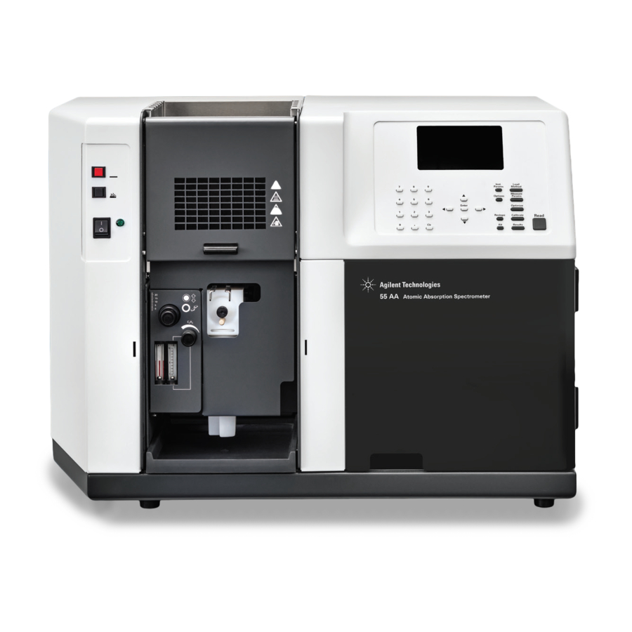
Documentation Conventions Specifications The Agilent 55B AA (double beam) flame atomic absorption spectrometer combines minimal user setup and fast sample throughput with unparalleled ease of use. The instrument is controlled via a built-in keyboard and display and can be upgraded by purchasing a PC and Agilent SpectrAA software (for more information, contact your local Agilent office). -
Page 34: Documentation
For optimum analytical performance it is recommended that the ambient temperature of the laboratory be between 20-25 °C (68-77 °F) and be held constant to within ±2 °C (±3.6 °F) throughout the entire working day. Agilent 55B AA Spectrometer User’s Guide... - Page 35 Front (lamp compartment) Deuterium lamp: Molex 3-way connection, behind lamp panel. Figure 2. Deuterium lamp cover panel WARNING Shock Hazard To maintain safety, only the deuterium lamp assembly should be used at this connection. Agilent 55B AA Spectrometer User’s Guide...
- Page 36 Recommended 75 kPa 350 kPa 350 kPa (11 psi) (50 psi) (50 psi) Normal flow 0-10 13.5-20 11-16 rate (L/min) Other gas connections Sample compartment: Push-on Air/N O connector for burner Push-on C connector for burner Agilent 55B AA Spectrometer User’s Guide...
-
Page 37: Overview
Sample compartment front panel Flame shield Chimney Provide a suitable waste vessel Instrument overview Use the following labeled picture as a guide when installing the various components of your Agilent AA system. Agilent 55B AA Spectrometer User’s Guide... - Page 38 Overview Figure 3. Agilent 55B AA flame atomic absorption spectrometer – front view Figure 4. Agilent 55B AA flame atomic absorption spectrometer – rear view Your Agilent AA instrument is supplied with a country kit that includes a set of gas hose fittings and a mains cable which suits the common utility standard of the local region.
-
Page 39: Power
Power requirements are detailed in the ‘Electrical Power Supplies’ section of the Agilent AA Site Preparation Guide. Ensure you comply with these electrical requirements before connecting the Agilent 55B AA system. Before connecting the instrument to the power supply, ensure: the spectrometer is turned OFF. -
Page 40: Moving Your Instrument
UV radiation. Power to the lamp is removed when the deuterium lamp panel is removed. Hollow cathode lamps Figure 7. Hollow cathode lamp Agilent 55B AA Spectrometer User’s Guide... -
Page 41: Deuterium (D ) Lamp
Page 124. Sample compartment Figure 6. Sample compartment The major components in the Sample Compartment includes: Nebulizer block assembly Nebulizer Spray chamber Burner Sample compartment front panel Flame shield Agilent 55B AA Spectrometer User’s Guide... -
Page 42: Nebulizer Block Assembly
The nebulizer block connects the following components: Nebulizer Impact bead Liquid trap Drain tube Spray chamber Figure 8. Nebulizer block assembly (for products with serial numbers 0110xxxx and later) Agilent 55B AA Spectrometer User’s Guide... - Page 43 The tubing should run parallel to the drain tubing and must slope downwards to prevent it becoming blocked should liquid overflow and drain from the vapor vent. CAUTION Do not lead the vapor vent tubing to the waste vessel. Agilent 55B AA Spectrometer User’s Guide...
- Page 44 The spray chamber contains the following components: mixing paddles pressure relief bung (also called the spray chamber bung). Agilent 55B AA Spectrometer User’s Guide...
- Page 45 Prevent ignition if the pressure relief bung is not correctly fitted. Shut down the flame if the bung is ejected because of a flashback. Instructions to To assemble the spray chamber are in the Maintenance section - Page 109. Agilent 55B AA Spectrometer User’s Guide...
-
Page 46: Burner
Never interfere with or attempt to bypass burner interlocks Never attempt to dismantle or modify a burner Sample compartment front panel The sample compartment front panel is designed to reduce heat and radiation hazards. Always fit this panel before using your instrument. Agilent 55B AA Spectrometer User’s Guide... -
Page 47: Flame Shield
Lower the flame shield until it rests on the stainless-steel bosses on either side of the sample compartment. To remove the flame shield, lift it up and unhook it from the front of the sample compartment. Agilent 55B AA Spectrometer User’s Guide... -
Page 48: Chimney
To fit the chimney: Hold the chimney over the sample compartment, with the warning information facing towards the front of the instrument. Lower the chimney onto the sample compartment. Agilent 55B AA Spectrometer User’s Guide... -
Page 49: Interface
Interface Front panel overview Navigating the interface Display pages This chapter provides an overview of the Agilent 55B AA user interface. Read through this chapter while exploring the interface. Figure 13. Front panel interface Front panel overview The front panel of the Agilent 55B AA consists of the following: Liquid Crystal Display—LCD. -
Page 50: Display Screen
Interface Figure 14. Agilent 55B AA front panel Display screen Figure 15. Display screen The display is divided into four areas: status area, signal bar, page area and message line, each of which is discussed below. Status area The status area displays the method details and solution results. Method details include settings relating to the method currently loaded, such as method number and element. - Page 51 No text (“ ”) indicates that the method has not been calibrated. Icons appear in the message line, to provide you with instrument status information. Some of these icons are animated, to indicate that the instrument is active. Agilent 55B AA Spectrometer User’s Guide...
- Page 52 Table 4. Gas type and oxidant pressure icons and their meaning Icon Meaning Air-acetylene, oxidant pressure present Air-acetylene, no oxidant pressure Air only, oxidant pressure present Air only, no oxidant pressure Nitrous oxide-acetylene, oxidant pressure present Nitrous oxide-acetylene, no oxidant pressure Agilent 55B AA Spectrometer User’s Guide...
-
Page 53: Keypad
The Calibrate key is also used, in conjunction with the Alt key, to view the calibration graph. There are other diagnostic pages accessed via key combinations. For details, refer to Alt key - Page 54. Agilent 55B AA Spectrometer User’s Guide... - Page 54 Alt key Figure 19. Alt key ‘Alt’ is used in conjunction with other keys to modify their meaning. Pressing ‘Alt’ alone has no effect. The table below lists the shortcuts available via the keypad. Agilent 55B AA Spectrometer User’s Guide...
- Page 55 Drop reslope standard Results page Right Prime SIPS pump page Results page Increment next sample Results page Down Decrement next sample Results page Clear Clear result window, start new page if Serial=PRINTER Results page Agilent 55B AA Spectrometer User’s Guide...
-
Page 56: Navigating The Interface
Command menus are single-level menus appearing in the left of the screen. Use the ‘Up’ and ‘Down’ keys to move from one item to the next, and, if necessary, press ‘Enter’ to select the desired option. Agilent 55B AA Spectrometer User’s Guide... - Page 57 An arrow appearing in the frame around a menu indicates there are additional options available. Use the Up/Down arrow keys to scroll through the list, or the Left/Right arrow keys to move from one menu to the next. Agilent 55B AA Spectrometer User’s Guide...
-
Page 58: Moving Between Fields
You should follow the prompts appearing on this page to load the type of method you want. For more information, refer to Method development. - Page 69. Instrument Parameters page The Instrument Parameters page is used to set the instrument parameters and the save and delete methods. Agilent 55B AA Spectrometer User’s Guide... - Page 59 Defines the wavelength to be used for the current element - default is the first listed wavelength. NOTE The listed wavelengths are element and instrument-mode specific. Other λ Defines the wavelength to be used when ‘Other’ is selected in the Wavelength field. Range is 180.0–900.0 nm. Agilent 55B AA Spectrometer User’s Guide...
-
Page 60: Measurement Parameters Page
Defines the number of readings per solution. This option is only available in Integration mode. Precision Defines the % precision for the PRecision Optimized Measurement Time (PROMT) measurement mode. Not available when SIPS is enabled. Agilent 55B AA Spectrometer User’s Guide... -
Page 61: Options Page
‘Read’ key takes the most recent replicate as the solution (sample or standard) result. This mode should NOT be used when the SIPS accessory is being used. SIPS Displays the following sub-menu: Figure 24. The SIPS sub-menu of options Agilent 55B AA Spectrometer User’s Guide... - Page 62 Further information on how to use SIPS is outlined in the Operation section – see Page 67. Serial port Displays the following sub-menu: Figure 25. The Serial port sub-menu of options Agilent 55B AA Spectrometer User’s Guide...
-
Page 63: Optimization Page
The signal bar at the top of the page facilitates optimization of the lamps, burner position, and impact bead position to obtain the strongest signal. Refer to ‘Optimization’ on page 74 for instructions on fine tuning the system. Agilent 55B AA Spectrometer User’s Guide... -
Page 64: Calibration Parameters Page
Results page The Results page displays the solution results in tabular format, and displays sample name, concentration, %RSD or precision, mean solution reading, dilution factor and the last replicate value. Figure 26. The Results page Agilent 55B AA Spectrometer User’s Guide... - Page 65 The contents of the Results page are cleared if: A new method is loaded, • The Measurement mode is changed or • The Instrument mode is changed • Agilent 55B AA Spectrometer User’s Guide...
- Page 66 Interface This page is intentionally left blank Agilent 55B AA Spectrometer User’s Guide...
-
Page 67: Operation
Method development Optimization Nebulizer setup Calibrate the method Sample measurement Results Shut down the system This chapter provides instructions for running your Agilent 55B AA instrument, including: How to develop methods. Optimize the system. Perform measurements and ... - Page 68 Optimize the system - see ‘Optimization’ on Page 74. Set the nebulizer uptake rate - see ‘Nebulizer setup’ on Page 81. Calibrate the system - see ‘Calibrate the method’ on Page 86. 10 Proceed with your analysis. Agilent 55B AA Spectrometer User’s Guide...
-
Page 69: Start The System
There are two types of methods— ‘user’ methods where settings are defined by the user and ‘cookbook’ methods. Select the language of the interface If the required language is displayed, skip this step. Agilent 55B AA Spectrometer User’s Guide... -
Page 70: Load A Method
Instrument mode Active lamp current Gas type Wavelength and • Slit width • In addition, all previous standard concentration values will be deleted. Enter concentration values before starting the analysis. Agilent 55B AA Spectrometer User’s Guide... -
Page 71: Save/Delete Methods
Move the highlight to the ‘Delete Method’ option and press Enter. Move the highlight to the method in the list to be deleted and press Enter. The method will be deleted, leaving an empty slot in the list. Agilent 55B AA Spectrometer User’s Guide... -
Page 72: Set The Instrument Parameters
Select the Measurement Parameters page and specify: ‘Next sample’ to be measured ‘Batch no‘ ‘Read time’ Number of ‘Replicates’ (Integration mode only) ‘Precision’ (PROMT mode only) ‘Pre-read delay’ Agilent 55B AA Spectrometer User’s Guide... -
Page 73: Define The Calibration Standards
Enter the remaining standard concentrations. The values must be unique and increasing. Set the reslope standard to be used by moving the cursor to the appropriate standard and pressing the Reslope key. An asterisk indicates the reslope standard. Agilent 55B AA Spectrometer User’s Guide... -
Page 74: Optimization
The Active lamp number can be found on the lamp holder and the Active current is printed on the lamp. Press the Optimize button and ensure nothing is in the optical path. The ‘HC lamp’ option is selected automatically upon entering the page. Maximize the signal: Agilent 55B AA Spectrometer User’s Guide... - Page 75 On the ‘Optimize’ page, select the ‘D lamp’ option. Maximize the signal. Watch the lamp signal bar on the display as you slowly turn one of the D2 lamp adjustment knobs located on the front of the D2 lamp compartment. Agilent 55B AA Spectrometer User’s Guide...
-
Page 76: Align The Burner
Rotate the burner by squeezing the prongs of the rotation handle, until the slot is parallel to the light path. Figure 31. Squeeze prongs of rotation handle to rotate burner Agilent 55B AA Spectrometer User’s Guide... - Page 77 Figure 33. Card with vertical line perpendicular to the slot Rotate the burner adjustment knobs (Figure 34 below) to position the burner horizontally and vertically with the light beam in the target area. Agilent 55B AA Spectrometer User’s Guide...
-
Page 78: Light The Flame
Dependent on the solvent used, ensure the ventilation tube is attached and is free of kinks and bends. The end of the tube must be positioned sloping downwards and be free of kinks or sharp bends so that the waste liquid can Agilent 55B AA Spectrometer User’s Guide... - Page 79 If the ignition sequence times out before the flame ignites, release the button, wait about five seconds, and restart the sequence. CAUTION If an error is displayed, ensure all safety interlocks have been satisfied before continuing. Do not attempt to bypass any safety interlock. Agilent 55B AA Spectrometer User’s Guide...
-
Page 80: Optimize The Flame Signal
The burner height controls the sensitivity and will also influence atomization interferences. Carefully move the burner horizontally by turning the inner adjustment knob on the burner adjuster. Watch the signal bar to obtain maximum absorbance. In Agilent 55B AA Spectrometer User’s Guide... -
Page 81: Nebulizer Setup
The setting of the thimble determines how close the impact bead is to the outlet of the capillary tube. This enables the optimal nebulizer setting based on the characteristics of your samples. Agilent 55B AA Spectrometer User’s Guide... -
Page 82: High Vacuum Setting
Slowly and carefully turn the thimble counter-clockwise until the absorbance reaches a maximum. Hold the thimble so it cannot turn, then turn the locking ring until it is firmly against the spray chamber body, locking the thimble in place. Agilent 55B AA Spectrometer User’s Guide... -
Page 83: Low Vacuum Setting
Aspirating distilled water, turn the thimble counter-clockwise until bubbles emerge from the end of the capillary tubing. Turn the thimble clockwise to the point where bubbling ceases. This is the zero-uptake point (no solution is being aspirated through the nebulizer). Agilent 55B AA Spectrometer User’s Guide... -
Page 84: Set The Uptake Rate For Organic Solvents
Flame types The appearance of the flame changes dependent on the fuel/oxidant mix. Typical flames are shown below: Figure 38. Air/Acetylene flames. Left to right – Lean, Stoichiometric, Rich Agilent 55B AA Spectrometer User’s Guide... -
Page 85: Performance Checks
Zero the instrument (press the Alt and Read keys together). Aspirate a solution of 5 mg/mL copper and note the absorbance reading. Agilent guarantee an absorbance of 0.75 or better using the Mark 7 flame atomization system under fully optimized conditions. Agilent 55B AA Spectrometer User’s Guide... -
Page 86: Calibrate The Method
Set up the SIPS 10 as described in the SIPS manual. Develop or modify a method. Enable SIPS on the Options page. In the SIPS sub-menu, set the required parameters. Press the Calibrate button to display the ‘Calibration Parameters page’. Agilent 55B AA Spectrometer User’s Guide... -
Page 87: Display The Calibration Graph
If you are using SIPS the Reslope standard defaults to Conc3. Aspirate the selected standard (if you are using SIPS the standard will be prepared automatically). On the Results page, press the Reslope key. Agilent 55B AA Spectrometer User’s Guide... -
Page 88: Sample Measurement
Set up the SIPS 10 as described in the SIPS manual. Select SIPS on the Options page and set the required parameters - see Page Set the remaining Instrument Parameters page as described in Page 58. Agilent 55B AA Spectrometer User’s Guide... -
Page 89: Results
Set the required ‘Baud rate’ and ‘Lines per page’. Ensure the instrument is connected to the printer. Press the Read key to measure the current solution. As each solution is measured, the result will be sent to the printer. Agilent 55B AA Spectrometer User’s Guide... -
Page 90: Output To Lims System
Shut off all gas supplies at the regulators and gas cylinders. Empty the waste vessel. Turn off the exhaust fan. Remove and Cleaning Any hardware according to the instructions in the Maintenance Chapter – see Page 93. Agilent 55B AA Spectrometer User’s Guide... -
Page 91: Maintenance
Burners Gas supplies Lamps Fuses This chapter describes how to maintain your Agilent 55B AA system. You should keep a record in your Instrument Log Book of all maintenance carried out. CAUTION Before you remove any hardware, you must shut down the instrument. -
Page 92: Maintenance Schedule - Nebulizer/Spray Chamber
Test the nebulizer for leaks. If any leakage is detected, replace the internal O-rings. Monthly Remove and check the nebulizer, re-install the nebulizer (outlined in the following section) and measure the uptake rate to verify the Performance checks– see Page 85. Agilent 55B AA Spectrometer User’s Guide... -
Page 93: Cleaning
If using an air compressor to supply the air, check the filters in the air supply line and clean if necessary. Nebulizer This section describes how to remove, disassemble, clean and reassemble your nebulizer. Agilent 55B AA Spectrometer User’s Guide... -
Page 94: Remove The Nebulizer Block
11 Separate the nebulizer block and spray chamber. Hold the nebulizer block firmly in one hand and twisting the spray chamber in a counter-clockwise direction to unlock the bayonet mount. 12 Disassemble the nebulizer as described in the following section. Agilent 55B AA Spectrometer User’s Guide... -
Page 95: Disassemble The Nebulizer
Use the large end of the nebulizer tool to unscrew the white plastic insert from the nebulizer body. NOTE If the white plastic insert has stripped threads. Remove the old insert as described above and insert a new white plastic insert. Agilent 55B AA Spectrometer User’s Guide... -
Page 96: Clean A Blocked Nebulizer
Instructions on how to clean a blocked nebulizer follows. Clean a blocked nebulizer Check the nebulizer body, capillary and venturi for corrosion. Nebulizer issues can be minimized by aspirating 50-500 mL of distilled water at the end of each working day. Agilent 55B AA Spectrometer User’s Guide... -
Page 97: Reassemble The Nebulizer Block
Reassemble the nebulizer block WARNING Fire Hazard, Explosion Hazard. Incorrect assembly and/or fitting of the nebulizer can create explosion hazards and fire hazards which can cause serious injury to personnel and damage to equipment and property. Agilent 55B AA Spectrometer User’s Guide... - Page 98 Figure 45. Insert Capillary Guide into the Nebulizer Block Place the large end of the venturi extraction tool over the capillary guide. Push down on the capillary guide and venturi. The venturi should protrude from the opposite end of the nebulizer block. Agilent 55B AA Spectrometer User’s Guide...
- Page 99 Figure 48. Capillary assembly and spring being inserted into the capillary guide. Screw the white plastic insert into the nebulizer block using the large end of the Nebulizer tool. Figure 49. Screw the white plastic insert into the Nebulizer block Agilent 55B AA Spectrometer User’s Guide...
- Page 100 Figure 51. Check spring function 11 Thread the thimble and locking ring over the capillary. 12 Screw the thimble onto the nebulizer body. Instructions on how to adjust the Nebulizer are detailed in ‘Nebulizer setup’ on Page 81. Agilent 55B AA Spectrometer User’s Guide...
-
Page 101: Impact Bead
Remove the nebulizer block from the sample compartment. Isolate the nebulizer block by Remove the nebulizer block, the liquid trap, drain tube and spray chamber -see Page 94. Loosen the Impact bead locking screw approximately two turns. Agilent 55B AA Spectrometer User’s Guide... - Page 102 You should only perform the remainder of this procedure if the bead is broken and trapped in the adjuster block. Loosen the Trapping screw 3-4 turns. The Trapping screw retains the Impact bead adjustment screw in the nebulizer block. Agilent 55B AA Spectrometer User’s Guide...
- Page 103 Clamping screw is sufficiently loosened. WARNING Eye Hazard This procedure may dislodge small fragments of glass. To protect the eyes from flying pieces of glass, protective eye wear should always be worn when performing this procedure. Agilent 55B AA Spectrometer User’s Guide...
- Page 104 Figure 59. Align holes to enable assembly with the Impact bead adjustment screw Replace the Impact bead adjustment screw by gently pushing past the O-ring. Figure 60. Insert the impact bead adjustment screw Agilent 55B AA Spectrometer User’s Guide...
- Page 105 Figure 62. Tighten the clamping screw – side of nebulizer Loosen the Clamping screw one-eighth of a turn. This restricts the horizontal movement of the Impact bead adjustment block. Figure 63. Clamp screw touching the impact bead adjustment block Agilent 55B AA Spectrometer User’s Guide...
- Page 106 Refer to the right-hand image in Figure 66 above. This will avoid breaking the impact bead after installation. 13 Carefully insert the tail of the Impact bead through the nebulizer block hole into the Impact bead adjustment block. Agilent 55B AA Spectrometer User’s Guide...
- Page 107 Check that the impact bead will not rotate under gentle pressure. 17 Turn the impact bead adjustment screw counter-clockwise until the block appears midway in the cutout in the nebulizer block. Figure 67. Centered impact adjustment block Agilent 55B AA Spectrometer User’s Guide...
-
Page 108: Spray Chamber
Twist and pull the pressure relief bung from the rear of the spray chamber. Inspect the O-ring and replace if cracked or deformed. Insert a blunt, inert object inserted through the front of the spray chamber. Push on the mixing paddles boss to remove the part. Agilent 55B AA Spectrometer User’s Guide... -
Page 109: To Clean The Spray Chamber
Position the front (boss end) of the mixing paddles in the opening at the rear (bung end) of the spray chamber, being careful not to contaminate them. Align the mixing paddles so that the edges of a pair of blades are vertical when installed. Agilent 55B AA Spectrometer User’s Guide... - Page 110 Lubricate the O-ring of the pressure relief bung with distilled water. Insert the pressure relief bung into the rear of the spray chamber. With a gentle twisting motion, firmly press the pressure relief bung as far as it will go into the spray chamber. Agilent 55B AA Spectrometer User’s Guide...
-
Page 111: Assemble The Spray Chamber And Nebulizer Block
Failure to install the drain tube will cause violent and loud explosions to occur in both the liquid trap and drain vessel when the flame is lit. The explosion may be severe enough to cause death, personal injury or damage to the instrument or laboratory. Agilent 55B AA Spectrometer User’s Guide... - Page 112 Figure 71. Lower the drain tube and float into the trap Push the trap home and then twist it 1/4 turn clockwise to lock it into position - see Figure 72 below. Figure 72. Lock the trap into position Agilent 55B AA Spectrometer User’s Guide...
-
Page 113: Installing The Spray Chamber/Nebulizer Assembly
Installing the spray chamber/nebulizer assembly CAUTION Always check the assembly before installing the spray chamber in the sample compartment. Especially check the correct positioning of the mixing. Agilent 55B AA Spectrometer User’s Guide... - Page 114 Do not accumulate large volumes of flammable liquid. Dispose of flammable liquids in accordance with local regulations. Attach a convenient length of 9 mm ID tubing to the lower outlet of the liquid trap. Agilent 55B AA Spectrometer User’s Guide...
- Page 115 Do not lead the vapor tubing to the waste vessel. WARNING Fire Hazard, Explosion Hazard. Failure to connect the vapor vent tubing correctly can cause a flashback or explosion. Ensure that the tubing is configured as described in the previous step. Agilent 55B AA Spectrometer User’s Guide...
-
Page 116: Burners
Replace a damaged or worn O-ring immediately. Position the burner in the sample compartment, with the slot along the optical path and the plate with the warning towards the front of the instrument. Agilent 55B AA Spectrometer User’s Guide... - Page 117 (Figure 79 below). Figure 78. Push the burner down, Figure 79. Squeeze Rotation Handle to rotate the avoid touching the burner slot, align the slot burner along the optical path. Agilent 55B AA Spectrometer User’s Guide...
-
Page 118: Clean The Burner
To remove the burner, gently twist the burner assembly as you lift it straight up out of the spray chamber. Using an Agilent burner cleaning and alignment card, gently scrape off any excessive carbon build up in the burner slot. Agilent 55B AA Spectrometer User’s Guide... - Page 119 11 Insert a clean Agilent burner cleaning and alignment card into the burner slot. 12 Use a dropper to pour a small amount of metal polishing fluid on each side of the burner cleaning card just above the burner slot. Agilent 55B AA Spectrometer User’s Guide...
- Page 120 14 Place some metal polishing liquid on the card and polish the outer surfaces along the top of the burner slot. Agilent 55B AA Spectrometer User’s Guide...
- Page 121 Table 9. Maximum allowable burner slot width Mark VIA 0.47 mm (0.0185 in.) Mark 7 0.46 mm (0.0181 in.) 0.54 mm (0.021 in.) Burners cannot be refurbished and must be replaced when the maximum slot widths are exceeded. Agilent 55B AA Spectrometer User’s Guide...
-
Page 122: Gas Supplies
Hold the lamp by its base and align the lamp base so that the ridge on the guide pin (see Figure 84 below) is matched with the notch in the socket (see Figure 85. Lamp socket – notch highlighted below). Agilent 55B AA Spectrometer User’s Guide... -
Page 123: Removing Hollow Cathode Lamps
The lamp will become very hot during operation and cause severe burns if touched. Allow time for the lamp to cool. Always wear protective gloves when handling a hot lamp. Hold the lamp by its base. Agilent 55B AA Spectrometer User’s Guide... -
Page 124: D 2 Lamp
Remove the hollow cathode lamp in position 1 if fitted. Undo the thumbscrew at the top of the D lamp compartment. Lift the lamp assembly up and out from the lamp compartment using the two lamp alignment screws. Agilent 55B AA Spectrometer User’s Guide... - Page 125 13 Replace the thumbscrew at the top of the D lamp compartment. NOTE After installation, a new D lamp must be aligned. Refer to Optimization for instructions on how to align lamps – see Page 74. Agilent 55B AA Spectrometer User’s Guide...
-
Page 126: Fuses
Remove the fuse holder, located to the right of the mains input connection as shown in Figure 89 below. Place the tip of a flat head screw driver into the slot (1). Figure 89. Fuse cover 1. Removal slot 2. Fuse holder Agilent 55B AA Spectrometer User’s Guide... - Page 127 Replace the fuse holder in the instrument and reconnect the instrument to the mains power supply. NOTE If a fuse blows repeatedly, it may indicate other problems with the instrument. Contact your local Agilent sales office and arrange a service call. Agilent 55B AA Spectrometer User’s Guide...
- Page 128 Maintenance This page is intentionally left blank Agilent 55B AA Spectrometer User’s Guide...
-
Page 129: Spare Parts
Other Covers/doors Fuses Miscellaneous This chapter contains information for your Agilent 55B AA spare parts. Unless otherwise specified, only Agilent supplied parts should be used. See the Agilent website for part number and ordering information at www.agilent.com. Sample lists Figure 90. Nebulizer components... - Page 130 O-ring, organics 15 Spray chamber, molding fluorinated 16 Mixing paddles 17 Pressure relief bung 18 O-ring, pressure relief bung, nitrile O-ring, pressure relief bung, organics 19 Air/acetylene burner, Mark 7 0/acetylene burner, Mark 7 Agilent 55B AA Spectrometer User’s Guide...
- Page 131 20 Impact bead – glass or PTFE (packet of 5) 21 Clamp bead adjuster 22 Impact bead locking screw (PEEK) 23 Trapping screw (stainless steel) 24 Plug grey PEEK 25 O-ring 3/16 in. ID Agilent 55B AA Spectrometer User’s Guide...
-
Page 132: Other
Nebulizer tool—capillary extraction Nebulizer tool—venture extraction Burner cleaning and alignment strip (packet of 100) Nebulizer cleaning wire Covers/doors Flame shield Sample compartment front panel (lower) Flame shield window only Fuses T4 A H 250 V Agilent 55B AA Spectrometer User’s Guide... -
Page 133: Miscellaneous
Drip tray Chimney Serial to parallel converter 240 V 110 V SpectrAA mouse mat Kit Agilent AA keyboard overlays Includes overlays in French, German, Italian and Spanish Kit spray chamber stand Remote read footswitch Agilent 55B AA Spectrometer User’s Guide... - Page 134 Spare Parts This page is intentionally left blank Agilent 55B AA Spectrometer User’s Guide...
-
Page 135: Troubleshooting/Errors
9320 No peak: high BC lamp energy 9321 No peak: low HC lamp energy 9322 No peak: high HC lamp energy 9323 Low emission: no peak 9324 High emission: no peak 9329 No peak detected 9330 No peak detected Agilent 55B AA Spectrometer User’s Guide... - Page 136 9921 Flame out detected 9922 Flame shutdown: gas type 9923 Flame ignition timeout 9934 Flame shutdown: host offline 9937 Flame pressure relief bung 9938 Liquid trap not ready 9xxx GPIB fault 9xxx Instrument error 9xxx SpectrAA error Agilent 55B AA Spectrometer User’s Guide...
-
Page 137: Common Problems
Turn off nearby lights. b) Flame sensor faulty. Igniter flame too a) Low acetylene pressure, check supply. short b) Check that igniter solenoid operates correctly. c) Check for blockage or carbon in igniter capillary. Agilent 55B AA Spectrometer User’s Guide... - Page 138 Check for chemical interference. e) Check fuel to oxidant ratio is correct. f) Check burner is clean and clear of deposits. g) Check solutions have not expired. h) Check wavelength selection and calibration. Agilent 55B AA Spectrometer User’s Guide...
- Page 139 Signal not increasing a) Check standard solutions (particularly high standard). and excessive b) Select a different wavelength. curvature c) Reduce lamp current. d) Reduce slit width. e) Operate within the working range (0.1 to 0.8 Abs). Agilent 55B AA Spectrometer User’s Guide...
-
Page 140: Error Messages
Check all cables to this unit are connected securely. 3800 EEPROM storage error A problem has been identified with the User Method storage device. The method parameters have failed to store or were retrieved with error and so ignored. Agilent 55B AA Spectrometer User’s Guide... -
Page 141: 5004 Signals Not Increasing
9159 EEPROM checksum zero wl The instrument will take several minutes to start up but will have no effect on operation. If the error persists, a service call may be required. Agilent 55B AA Spectrometer User’s Guide... -
Page 142: 9160 Eeprom Checksum Mono Correction
Possible causes include: Power supply failure. Faulty RBC (Rotating Beam Combiner) on double beam instruments only. Faulty Mains Supply to the instrument. If the error persists, a service call may be required. Agilent 55B AA Spectrometer User’s Guide... -
Page 143: 9310 Optical Rbc Frequency
Wide range: up to 900 nm. 9317 No peak: low HC lamp energy Low hollow cathode lamp energy. The instrument Gain had been raised to its highest value but the hollow cathode lamp signal was too low. Agilent 55B AA Spectrometer User’s Guide... -
Page 144: 9318 No Peak: High Hc Lamp Energy
Faulty D lamp or circuits. 9320 No peak: high BC lamp energy High Background Corrector (D )lamp energy. Possible causes include: lamp misaligned. Faulty D lamp. Faulty PMT or related circuits. Agilent 55B AA Spectrometer User’s Guide... -
Page 145: 9321 No Peak: Low Hc Lamp Energy
Flame not lit, or correctly aligned. Wrong wavelength selected. The standard solution currently being aspirated has low concentration. Emission Setup has not been performed. Faulty PMT or related circuits. Agilent 55B AA Spectrometer User’s Guide... -
Page 146: 9324 High Emission: No Peak
The instrument failed to peak at the selected wavelength. Another peak may be near this wavelength. Incorrect or noisy readings will result if the instrument is not optimized again. Possible causes include: Wrong hollow cathode lamp. Wrong wavelength or method selected. Agilent 55B AA Spectrometer User’s Guide... -
Page 147: 9337 Instrument Fault 310V Psu
The instrument could not detect any lamp current for the selected hollow cathode lamp. Possible causes include: No hollow cathode lamp is installed in the selected lamp position. Faulty hollow cathode lamp. Faulty lamp supply circuits. Agilent 55B AA Spectrometer User’s Guide... -
Page 148: 9514 Instrument Signal Saturation
Faulty PMT or circuits. The lamp was in the wrong position when the instrument was optimized. 9524 Low BC lamp energy Low Background Corrector (D ) lamp energy. Possible causes include: Agilent 55B AA Spectrometer User’s Guide... -
Page 149: 9525 High Bc Lamp Energy
9530 Instrument fault: signal diagnostics Instrument Fault. The instrument detected a problem with the signal electronics on the control board. Restart the instrument. If the problem persists a service call will be required. Agilent 55B AA Spectrometer User’s Guide... -
Page 150: 9531 No Lamp Current Detected
There is no flame control unit fitted to this instrument. An attempt was made to load a flame method. 9915 Flame shield open The flame shield was detected open or removed when the gas-box attempted to ignite the flame. Agilent 55B AA Spectrometer User’s Guide... -
Page 151: 9916 Fault: Gas Pressure Sensor
The detector may be faulty. 9922 Flame shutdown: gas type This is an internal system error. If a flame was present this error will cause the flame to be shut down for safety reasons. Agilent 55B AA Spectrometer User’s Guide... -
Page 152: 9923 Flame Ignition Timeout
Agilent trained and certified personnel. 9xxx SpectrAA error This is an internal instrument error and should not occur. Record the actual error number (e.g. 9903). Restart the instrument. If the error persists, contact Agilent trained and certified personnel. Agilent 55B AA Spectrometer User’s Guide... - Page 154 Software and Hardware Installation Operation of Hardware and Software Maintenance Procedures Instrument Cleaning Spare Parts Troubleshooting www.agilent.com © Agilent Technologies, Inc. 1997, 2000, 2002, 2009-2010, 2012-2013, 2016-2017, 2019 Edition 14, 4/19 *8510154100* 8510154100...