Assa Abloy SW300 Installation And Service Manual
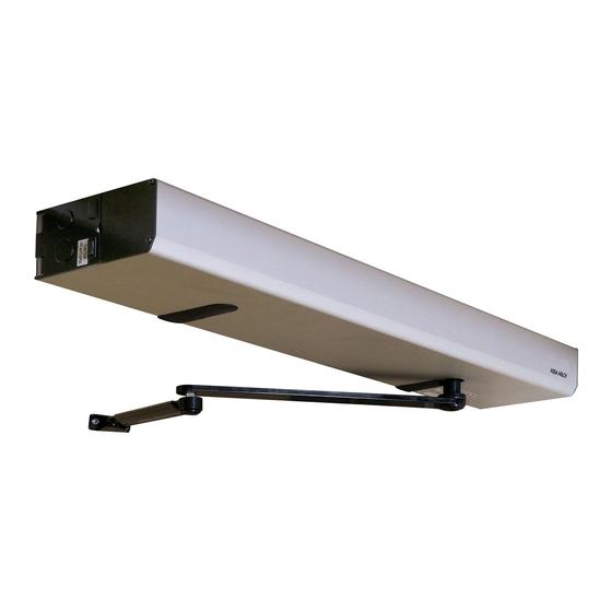
Swing door operator
Hide thumbs
Also See for SW300:
- User manual (414 pages) ,
- Installation and service manual (94 pages) ,
- Installation and service manual (85 pages)

Subscribe to Our Youtube Channel
Related Manuals for Assa Abloy SW300


Summary of Contents for Assa Abloy SW300
- Page 1 Installation and Service Manual Entrance Systems Swing Door Operator Original instructions ASSA ABLOY SW300, SW150 Original instructions...
- Page 2 ASSA ABLOY as word and logo are trademarks owned by the ASSA ABLOY Group © ASSA ABLOY Entrance Systems, 2024 Technical data subject to change without notice. Backtrack information: folder:Workspace Main, version:a824, Date:2024-01-15 time:08:49:59, state: Frozen...
-
Page 3: Table Of Contents
Electronic equipment reception interference ........................Environmental requirements ..............................Technical specifications ................................ Permitted door weight and door width for ASSA ABLOY SW300 ................. Permitted door weight and door width for ASSA ABLOY SW150 ................. How the ASSA ABLOY SW300 and ASSA ABLOY SW150 work ................ - Page 4 Battery backup unit ..................................10.7 Cover piece kit ....................................10.8 Closing time board kit (only for ASSA ABLOY SW300) ...................... 10.9 Fire kit (only for ASSA ABLOY SW300) ............................ 10.10 Mounting plate (for reinforcement of wall) ......................... 10.11 Labels .........................................
- Page 5 Advanced settings .................................. 17.1 Learn with advanced setting of “back-check and latch-check” ..................17.2 Revert to default values for “back-check and latch-check" (Level 1) ................17.3 Changing group of parameters (Level 2) ..........................17.4 Classification (Level 3) ................................. 17.5 Overhead Presence Detection and Interlock (Level 4) ..................... 17.6 Enhanced Lock Kick, Fire Input and Extended Arm Selection (Level 5) ...............
- Page 6 Issue 2024-01-15 1007913-en-28.0...
-
Page 7: Revision
1 Revision Revision Following pages have been revised: Page Revision 27.0 → 28.0 Added the different measurement between the washer and hexagon nut. Added the different measurement between the washer and hexagon nut. Added the different measurement between the washer and hexagon nut. 1007913-en-28.0 Issue 2024-01-15... -
Page 8: Presentation Of Notes And Warning Signs
2 Presentation of notes and warning signs Presentation of notes and warning signs Various symbols and texts are used in this manual for easier understanding and identification. Note! When you see Note! it contains useful advice and information to ensure correct and com- pliant usage of the system. -
Page 9: Warning: Important Safety Instructions. Follow All Instructions Since Incorrect Installation Can Lead To Severe Injury
3 WARNING: Important safety instructions. Follow all instructions since incorrect installation can lead to severe injury. WARNING: Important safety instructions. Follow all instructions since incorrect installation can lead to severe injury. • Failure to observe the information in this manual may result in personal injury or damage to equipment. - Page 10 3 WARNING: Important safety instructions. Follow all instructions since incorrect installation can lead to severe injury. • The operator can be used by persons with impaired physical, sensory or mental capacity if they have been instructed by a person in charge of their safety concerning use of the appliance in a safe way and understand the hazards involved.
- Page 11 3 WARNING: Important safety instructions. Follow all instructions since incorrect installation can lead to severe injury. • Ensure that entrapment between the driven part and the surround- ing fixed parts due to the opening movement of the driven part is avoided.
-
Page 12: Important Information
SW300 is an electromechanical operator approved for fire door applications. The ASSA ABLOY SW300 and ASSA ABLOY SW150 are to be installed indoors where they are suitable for almost all types of external and internal swing doors. This widely-used operators can be found in applications ranging from handicapped-access in private homes to high-traffic retail operations. -
Page 13: Electronic Equipment Reception Interference
Environmental requirements ASSA ABLOY Entrance Systems products are equipped with electronics and may also be equipped with batteries containing materials which are hazardous to the environment. Disconnect power before removing electronics and battery and make sure it is disposed of properly according to local regulations (how and where) as was done with the packaging material. -
Page 14: Technical Specifications
ASSA ABLOY Entrance Systems AB Address: Lodjursgatan 10, SE-261 44 Landskrona, Sweden Type: ASSA ABLOY SW300 and ASSA ABLOY SW150 Mains supply: 100-240 V AC +10/-15%, 50/60 Hz, mains fuse max 10A (building install- ation) Note! The mains supply shall be installed with protection and an all- pole mains switch with isolating capability of Category III, at least 3 mm between contacts, shall be installed according to local regulations. -
Page 15: Permitted Door Weight And Door Width For Assa Abloy Sw300
5 Technical specifications This product is to be installed internally. Permitted door weight and door width for ASSA ABLOY SW300 J=140 kgm² PUSH arm PUSH arm PUSH arm PULL arm PULL arm J=80 kgm² PULL arm Door width (m) 1007913-en-28.0... -
Page 16: Permitted Door Weight And Door Width For Assa Abloy Sw150
5 Technical specifications Permitted door weight and door width for ASSA ABLOY SW150 J=70 kgm² PUSH arm PUSH arm PULL arm PULL arm J=40 kgm² Door width (m) Issue 2024-01-15 1007913-en-28.0... -
Page 17: How The Assa Abloy Sw300 And Assa Abloy Sw150 Work
How the ASSA ABLOY SW300 and ASSA ABLOY SW150 work The swing door operators ASSA ABLOY SW300 and ASSA ABLOY SW150 use a DC motor which is connected to the output shaft by a combination of a worm gear and spur gears. The push- or pull arm system that is connected to the output shaft opens the door in a surface mounted application. -
Page 18: Opening
6 How the ASSA ABLOY SW300 and ASSA ABLOY SW150 work Opening When an activation signal is received by the control unit, the door is opened at the installer-adjusted opening speed. Before the door is fully open at back check, it slows automatically to low speed. -
Page 19: Extended Closing Torque (Cltq)
6 How the ASSA ABLOY SW300 and ASSA ABLOY SW150 work 6.4.3 Extended closing torque (CLTQ) If the potentiometer CLTQ is set to 0°, the door will close with normal spring power. If the poten- tiometer is turned clockwise, the motor will increase the closing torque. Extended closing torque will be reduced to zero: •... -
Page 20: Mat
6 How the ASSA ABLOY SW300 and ASSA ABLOY SW150 work 6.4.9 Mat safety means that: • a closed door will not open, if someone steps on the mat • an open door will not close, if someone steps on the mat •... -
Page 21: Program Selector (Wall Mounted)
6 How the ASSA ABLOY SW300 and ASSA ABLOY SW150 work • If the door cannot fully close, the operator will perform a lock retry (once if manually, twice if automatically open). 6.5.3 Program selector (wall mounted) • Input for OPEN, EXIT and OFF (if no program selector, AUTO is default). -
Page 22: Nurse And Bed Functionality
6 How the ASSA ABLOY SW300 and ASSA ABLOY SW150 work 6.5.7 Nurse and bed functionality Solution 1 Connect a bridge between 3 and 7 on the secondary EXU-SI. Use any impulse on primary to open primary door. Use Open/Close impulse on secondary to open both doors. -
Page 23: Presence Detection Swingpath, Door Mounted
6 How the ASSA ABLOY SW300 and ASSA ABLOY SW150 work 6.6.2 Presence detection swingpath, door mounted When a sensor that is mounted on the swing side of a door detects an object, it will send a command to the control unit to stall the door. If the control unit has received a short signal from the sensor and there is still hold open time left on the control unit, the door will continue on its way open if the object has cleared. -
Page 24: Models
7 Models Models Three main models of the ASSA ABLOY SW300 and ASSA ABLOY SW150 are available: • Single doors • Double doors (two operators) • Double egress doors (two operators) The operators are non-handed and not dependent on the hinges. The operators suit both pushing and pulling arm systems. -
Page 25: Double Operator, Surface Mounted
7 Models Double operator, surface mounted The product is delivered complete with back plate, control unit, end plates and cover. Total cover length CL includes end plates. Two operators can be mounted under the same cover (full length or a modular) to open one door each. -
Page 26: Part Identification
8 Part identification Part identification Issue 2024-01-15 1007913-en-28.0... - Page 27 Cable sync kit 330000331 Battery extension cable 331009105 Encoder cable 331009148 Transmission unit kit SW150 331007819F Transmission unit kit SW300 331007845 Micro switch kit 331007849 Stop arm kit 331008333 Control unit CU-300 without EXU-boards 331008349 Control unit CU-300 with EXU-SA/SI boards...
-
Page 28: Arm Systems
9 Arm systems Arm systems The installation process of arm systems is the same for Fire door installations, Basic installations and Inverse installations. Pushing installation with PUSH-arm This arm system is delivered with drive arm, telescopic part and door fitting. It is used if the oper- ator is installed on the wall on the opposite side of the door swing, and approved for fire door ap- plication for A up to 300 mm. -
Page 29: Pulling Installation With Pull-Arm
9 Arm systems Pulling installation with PULL-arm This arm system is delivered with drive arm, guide shoe and door fitting. Approved for fire door application for A up to 130 mm. PULL, 1008401BK/SI (A = -20-130 mm, B = 150 mm) PULL-220, 1011998BK/SI (A = -20-65 mm, B = 150 mm), only for LE Performance PULL-600, 1014729BK/SI (A = -20-230 mm, B = 250/420 mm) 20 mm extension... -
Page 30: Pushing Installation With Pull-Arm
9 Arm systems Pushing installation with PULL-arm This arm system consists of main arm, slide track, guide shoe and shaft adapter. It can be fitted on combinations of doors and jambs (walls), where the wall thickness does not exceed approx. 114 mm. -
Page 31: Double Acting Kits
9 Arm systems Double acting kits One way automatic opening and opposite way panic opening. Identify the automatic opening, sliding PUSH or PULL. Opposite direction will be the manual break- away. RH/DIN, 1014091BK/SI LH/DIN, 1014090BK/SI Sliding PUSH PULL Automatic Automatic Automatic Automatic 1007913-en-28.0... -
Page 32: Drive Shaft Extension Kits
9 Arm systems Drive shaft extension kits 70 mm 70 mm 50 mm 50 mm 20 mm 20 mm Art. No.: 1008396BK/SI Art. No.: 1008398BK/SI Art. No.: 1008400BK/SI Art. no: xxxxx Art. no: xxxxx Art. no: xxxxx Lower adapter M10, used for 20 mm lower installation height. Art. -
Page 33: Options
10 Options Options 10.1 Control switches 10.1.1 4-position switch PS-4C (operates the electric lock) Position Function The door is closed. The door cannot be opened with inner and outer activation units. The door is locked if an electromechanical locking device has been fitted. The door can be opened with a key switch (if fitted). -
Page 34: Coordination Unit (Only For Assa Abloy Sw300)
10 Options 10.4 Coordination unit (only for ASSA ABLOY SW300) To coordinate rebated doors in a double door installation and to make sure the doors are closed in right order. See page for installation and adjustment. Art. No. Description 1013027... -
Page 35: Cover Piece Kit
Cover piece kit Art. No.: 1009686BK/SI Art. No.: 1021281BK/SI 10.8 Closing time board kit (only for ASSA ABLOY SW300) To fulfill the DIN 18263-4 standard it is necessary to mount and connect this board to the lock kick. Art. No.: 1010374 10.9 Fire kit (only for ASSA ABLOY SW300) For fire door installations. -
Page 36: Labels
10.11 Labels Label kit- including all below Art. No.: 1005227 Emergency break-out, DIN right door Emergency break-out, DIN left door Click! Activation by disabled people Operator designed for disabled people Supervision of child ASSA ABLOY door sticker Issue 2024-01-15 1007913-en-28.0... -
Page 37: Iot Gateway 2.0
10 Options 10.12 IoT Gateway 2.0 10.12.1 Jumper setting a Open the IoT Gateway 2.0 unit by removing the four screws and removing the bottom plate. 1007913-en-28.0 Issue 2024-01-15... -
Page 38: Pairing And Configuring Iot Gateway 2.0 With Insight
10 Options Put the jumpers in these positions (the jumpers are packed in a plastic bag in the IoT Gateway 2.0 package). Make sure there is no jumper in this position. Verify that the jumpers are placed correctly. The circuit board risk being damaged if the jumpers are placed incorrectly when powered on. - Page 39 Select the door. e Enter the serial number of your IoT Gateway 2.0 unit, found on the label on the IoT Gateway 2.0 unit (e.g. ES01_00000). ASSA ABLOY Entrance Systems AB LODJURSGATAN 10 261 44 LANDSKRONA SWEDEN 24 VDC / 1A IoT Gateway 2.0...
- Page 40 10 Options Configure the door (if needed). g The door is now connected, and can be found in the Equipment page. Issue 2024-01-15 1007913-en-28.0...
-
Page 41: Fixing
10 Options 10.12.3 Fixing a Choose an appropriate place with good signal quality to fix the IoT Gateway 2.0 unit on. b Prepare the hole pattern where the IoT Gateway 2.0 unit shall be fixed. c Fix the IoT Gateway 2.0 unit properly, based on what surface you fix it onto. d IoT Gateway 2.0 unit fully fixed. -
Page 42: Connection
Connection Mount and connect GPIO according to installation drawing 1021699. Make sure to securely fix the cable to the wall! 10.12.5 ASSA ABLOY IoT Gateway 2.0 LED Indication table LED description Steady green LED Power to the IoT Gateway 2.0. -
Page 43: Pre-Installation
11 Pre-installation Pre-installation 11.1 General tips/Safety concerns In all instances, where work is being done, the area is to be secured from ped- estrian traffic to prevent injury. In all instances, where work is being done, the main power is to be removed to prevent injury. -
Page 44: Operator/Door Handing
11 Pre-installation 11.2 Operator/Door handing Operator/Door handing (DIN Right or DIN Left) is determined by which side the hinges are mounted seen from the swing side. DIN Left DIN Right DIN Left DIN Right ILL-01625 11.3 Installation examples Non combustible materi- al in fire application Non combustible ma- terial in fire application... -
Page 45: Fastening Requirements (But Not Included)
Brick wall Expansion-shell bolt, min. M6x85, UPAT PSEA B10/25, min. 50 mm from the underside * ASSA ABLOY Entrance Systems minimum recommended requirements. Building Codes may give different specifications. ** Thinner wall profiles (3-5 mm) must be reinforced with rivet nuts. -
Page 46: Tools Required
11 Pre-installation 11.5 Tools required • Metric Allen keys 1.5, 2.5, 3, 4, 5 and 6 mm • Torque wrench 120 Ncm, 8 Nm, 14 Nm and 50 Nm • Allen key 1.5, 2.5 and 3 mm with spherical tip •... -
Page 47: Mechanical Installation
12 Mechanical installation Mechanical installation The operator is mounted on either side of the door header depending on type of doors. The door is controlled with a push or pull arm system. If a coordination unit is to be installed on a double door installation, mount the coordinator base with rotor before mounting the transmission unit, see page 73. - Page 48 12 Mechanical installation A = 192 B = 557 Issue 2024-01-15 1007913-en-28.0...
- Page 49 12 Mechanical installation A = 192 B = 557 1007913-en-28.0 Issue 2024-01-15...
- Page 50 12 Mechanical installation A = 192 B = 557 150 mm 42 mm Issue 2024-01-15 1007913-en-28.0...
-
Page 51: Push Arm System
12 Mechanical installation 12.1 PUSH arm system PUSH 51 mm 2 - 25 mm 25 - 45 mm 71 mm 20 mm 45 - 75 mm 101 mm 50 mm 75 - 95 mm 121 mm 70 mm 0 - 367 Reveal 1007913-en-28.0 Issue 2024-01-15... - Page 52 12 Mechanical installation Operator with PUSH arm system DIN Right DIN Right (mm) (mm) Cable inlet Note! Screw head must be flush with back plate surface. 8 Nm Note! Be careful when installing the drive unit with the stop C L 2 arm underneath.
- Page 53 12 Mechanical installation Continuous "Operator with PUSH arm system" DIN Left DIN Left (mm) (mm) Cable inlet Note! Screw head must be flush with back plate surface. C L 1 C L 2 8 Nm C L 1 C L 2 1007913-en-28.0 Issue 2024-01-15...
- Page 54 DIN Left DIN Right DIN Right DIN Left 20° 1. Pre-tension the spring Note! Only ASSA ABLOY SW300 , not ASSA ABLOY SW150 2. Secure the pre-tension by the pin Let the stop arm locator and the stop arm be loose.
- Page 55 12 Mechanical installation Continuous "Operator with PUSH arm system" MARK Align the marks between arm and adaptor. Align the arm with the operator mark. Tighten the screw temporary to keep the arm in place. 90° Loosen the four screws. (2x) Fasten the arm system to the door.
- Page 56 12 Mechanical installation 10 lbf·ft (14 Nm) 14 Nm Tighten the four screws. The door must be closed. Hold the door a bit open and re- move the start position pin. 50 Nm 50 Nm Note! Important to make sure you tighten with 50 Nm before finalizing the mechanical installation! See the table on page for available extensions.
-
Page 57: Pull Arm System
12 Mechanical installation 12.2 PULL arm system Slim slide track PULL 48 mm 20 mm 68 mm 50 mm 98 mm 70 mm 118 mm A = -20-130 Note! Measurement Z must be reduced by 20 mm if lower adapter from kit 1010296BK/SI is used. 1007913-en-28.0 Issue 2024-01-15... - Page 58 12 Mechanical installation Operator with PULL arm system DIN Left DIN Left (mm) (mm) Cable inlet Note! Screw head must be flush with back plate surface. 8 Nm Note! Be careful when installing the drive unit with the stop C L 2 arm underneath.
- Page 59 12 Mechanical installation Continuous "Operator with PULL arm system" DIN Right DIN Right (mm) (mm) Cable inlet Note! Screw head must be flush with back plate surface. 6 5 2 C L1 C L 2 8 Nm C L 1 C L 2 1007913-en-28.0 Issue 2024-01-15...
- Page 60 Continuous "Operator with PULL arm system" DIN Right DIN Right DIN Left DIN Left 20° Note! Only ASSA ABLOY SW300 , not ASSA ABLOY SW150 Let the stop arm locator and the stop arm be loose. Do not tighten. Issue 2024-01-15...
- Page 61 12 Mechanical installation Slim slide track Attach the slide track (1) to the door with the guide shoe (2) fitted into the track. Use appropriate screws. Click Click Slide track Guide shoe 1007913-en-28.0 Issue 2024-01-15...
- Page 62 12 Mechanical installation Continuous. "Operator with PULL arm system" It is important to align the marks correctly. If necessary move one mark at a time. This corresponds to approx. 3° and will give a precision of ±1,5°. Align the marks. 50 Nm 50 Nm Note! Important to make sure you tighten with 50 Nm before finalizing...
-
Page 63: Operator With Sliding Push Arm System
12 Mechanical installation 12.3 Operator with sliding PUSH arm system Slim slide track PUSH 48 mm 2-25 mm 20 mm 68 mm 25-45 mm 50 mm 98 mm 45-75 mm 70 mm 75-95 mm 118 mm Max. 114 mm Max. 114 Reveal See instructions for PULL installation. -
Page 64: Assa Abloy Sw300 Inverse Installation With Push Arm System
12 Mechanical installation 12.4 ASSA ABLOY SW300 inverse installation with PUSH arm system Remove the microswitch lever (1), but not the microswitch (2). Microswitch lever Micro switch Stop arm Note! Set dip switch INV to ON for Inverse operation, see 13.1.1... - Page 65 12 Mechanical installation Inverse operator with PUSH arm system DIN Right DIN Right (mm) (mm) Cable inlet Note! Screw head must be flush with back plate surface. 8 Nm C L 2 C L 1 1007913-en-28.0 Issue 2024-01-15...
- Page 66 12 Mechanical installation Continuous "Inverse operator with PUSH arm system" DIN Left DIN Left (mm) (mm) Cable inlet Note! Screw head must be flush with back plate surface. C L 1 C L 2 8 Nm C L 1 C L 2 Issue 2024-01-15 1007913-en-28.0...
- Page 67 12 Mechanical installation Continuous "Inverse operator with PUSH arm system" DIN Left DIN Right DIN Right DIN Left Let the stop arm locator and the stop arm be loose. Do not tighten. Splines should not be engaged. 1007913-en-28.0 Issue 2024-01-15...
- Page 68 12 Mechanical installation Continuous "Inverse operator with PUSH arm system" 90° Loosen the four screws. Align the marks between arm and adaptor. Tighten the four screws. The door must be closed. 14 Nm 14 Nm (2x) Fasten the arm system to the door. Open the door to fully open position.
-
Page 69: Assa Abloy Sw300 Inverse Installation With Pull Arm System
12 Mechanical installation 12.5 ASSA ABLOY SW300 inverse installation with PULL arm system Remove the microswitch lever (1), but not the microswitch (2). Microswitch lever Micro switch Stop arm Note! Set dip switch INV to ON for Inverse operation, see 13.1.1... - Page 70 12 Mechanical installation Inverse operator with PULL arm system DIN Left DIN Left (mm) (mm) Cable inlet Note! Screw head must be flush with back plate surface. 8 Nm C L 2 C L 1 Issue 2024-01-15 1007913-en-28.0...
- Page 71 12 Mechanical installation Continuous "Inverse operator with PULL arm system" DIN Right DIN Right (mm) (mm) Cable inlet Note! Screw head must be flush with back plate surface. 6 5 2 C L1 C L 2 8 Nm C L 1 C L 2 Note! Be careful when installing the drive unit with the stop arm underneath.
- Page 72 12 Mechanical installation Continuous "Inverse operator with PULL arm system" DIN Right DIN Left DIN Right DIN Left Let the stop arm locator and the stop arm be loose. Do not tighten, splines should not be engaged. 50 Nm Open the door in fully Make sure that the door opens to an angle of 95-110°.
-
Page 73: Installation Of Coordination Unit On Fire Door Installations
12 Mechanical installation 12.6 Installation of coordination unit on Fire Door installations Before installing the transmission unit do step a-e below. Screw in the two steering pins (1) for the coordinator base. Steering pin Mount the rotor (parts 2 to 4 below) before the motor is installed on the back plate. Install the control unit when the installation of the coordination unit is completed. - Page 74 12 Mechanical installation d Mount the rotor (4) on the motor unit (7) with the screw (5) and washer (6) on the primary drive unit = for the door that opens first and closes last. Rotor Screw Washer Motor unit e Release the brake (26) by pushing in the linkage arm (14), so that the brake (26) is opened, push the fork (27) into the the coordinator base (15).
- Page 75 12 Mechanical installation Mount the coordinator base (15) with the two screws (8) on the primary drive unit. Remove the screw (9) and throw the washer (24) away when mount the acceptor (11) on the adjuster (10). Mount the screw (9) through the acceptor (11). g Mount the transmission unit.
- Page 76 12 Mechanical installation Mount the link rod (12) with its adaptor (13) into the linkage arm (14). Link rod Adaptor Linkage arm Mount on the other side of the link rod (12) to the secondary motor unit with the signal (16). Fasten the stop screw (17) with a torque of 120 Ncm.
- Page 77 12 Mechanical installation k Adjust the release of the brake by loosening the joint (18) and turning the link rod (12) close to the primary drive unit. Make the angle between the doors near closed position. Tighten screws (18) to 120 Ncm Link rod Joint Route the cables, see illustrations on page 48.
- Page 78 12 Mechanical installation n Mount the follower roller (20) at the leading edge close to the top of the secondary door leaf (21) with the appropriate screws (23). Follower roller Secondary door leaf Primary door leaf Screw Issue 2024-01-15 1007913-en-28.0...
-
Page 79: Electrical Connection
13 Electrical connection Electrical connection During any work with the electrical connections the mains must be disconnected. • Place the electric switch easily accessible from the operator. If an plug contact is used in the installation the wall socket shall be placed easily accessible from the operator. •... - Page 80 13 Electrical connection Alt.2 (Optional) Alt.3 (Optional) Alt.4 (Optional) 10AT Alt.5 (Optional) 10AT Note! Also connect the ground cable from the bracket. Protective lid Connection block Issue 2024-01-15 1007913-en-28.0...
-
Page 81: Control Units
13 Electrical connection 13.1 Control units 13.1.1 CU-300 Synchronizing of double doors Key hold open time Hold open time DIP-switch Closing torque Encoder Symmetric cam (jumper off) Asymmetric cam (jumper on) Motor Program selector PUSH 2 3 4 5 6 7 Motor +24V DC PULL... -
Page 82: Extension Units Exu-Si / Exu-Sa
13 Electrical connection 13.1.3 Extension units EXU-SI / EXU-SA Installation Torx T10 EXU-SA 5 mm nut driver Electrical power contact EXU-SI Tag strip long 2 pcs EXU short 1 pc EXU CU-300 Issue 2024-01-15 1007913-en-28.0... -
Page 83: Extension Unit Exu-Si
13 Electrical connection 13.1.4 Extension unit EXU-SI This extension unit has inputs for electro-mechanical lock, program selector, batteries, KILL function, OPEN/CLOSE, KEY opening and outer impulse. Functions Battery backup unit +24 V DC (+) 24 VDC OPEN Program selector EXIT Unlocked signal from lock KRST KILL reset (see jumper below) -
Page 84: Extension Unit Exu-Sa
13 Electrical connection 13.1.5 Extension unit EXU-SA This extension unit has inputs for door mounted sensors, which can give presence impulse on approach side and/or presence detection on swing path side. Relay output for error indication or door indication is also integ- rated. -
Page 85: Installation On Double Doors
13 Electrical connection 13.1.6 Installation on double doors If the operators are to be mounted at the same height with pushing and pulling arm systems, the height is determined by the pulling arm system, PULL. The pushing arm system PUSH must always have a shaft extension, minimum 50 mm, maximum 70 mm to match the mounting heights visually. -
Page 86: Double Door Installations
13 Electrical connection 13.3 Double door installations There are four different types of double door installations: • Rebated Has an overlapping primary door, can be opened synchronously if it is not jamming and must be closed asynchronously to avoid that the doors will jam or close in the wrong order. •... -
Page 87: Sensor Cable Inlet
13 Electrical connection 13.5 Sensor cable inlet Art. No.: 1007567 Alt. 1 Alt. 1 ø 3.7 Alt. 2 Alt. 2 Art. No.: 1015368BK/SI Art. No.: 1015368 1007913-en-28.0 Issue 2024-01-15... -
Page 88: Reset And Indication Device For Fire Doors
13 Electrical connection 13.6 Reset and indication device for Fire Doors Art. No.: 1009828 CL=840 CL= Optional CL=840 CL=Optional Reset & Indication device Reset & Indication device Smoke detector B Smoke detector ø 3.7 Issue 2024-01-15 1007913-en-28.0... - Page 89 13 Electrical connection CU-300 Master CU-300 primary 2 3 4 5 6 7 OK (Green) ALARM (red) EXU-SI primary EXU-SI Master NC Kill switch Fire alarm reset NC Kill switch (Parameter group 13) Fire alarm reset 0.5 s Additional smoke Kill switch and close Kill switch and detector is connected...
-
Page 90: Start-Up
Start-up 14.1 ASSA ABLOY SW300 spring pre-tension The spring pre-tension is factory set to EN4. The closing torque (spring force in power off) is adjusted by a hexagon nut placed at the end of the spring. Turning the nut clockwise increases the force. One turn equals a torque change of approx. -
Page 91: Micro Switch (Only For Assa Abloy Sw300)
14 Start-up 14.2 Micro switch (only for ASSA ABLOY SW300) Check and adjust the micro switch, controlling the lock kick at power failure. 3° 10° 3-10° 14.3 Adjusting the door stop a Close the door. b Open the door to required open position, plus approx. 15 mm. Put a doorbuffer under the door. - Page 92 14 Start-up d When stop arm is on the bottom of the operator, loose the stop arm locator and the stop arm. Mount the stop arm on the splines, as close as possible to the stop block 3). Mount the stop arm locator.
-
Page 93: Auto-Learn-Automatically Sets Back And Latch Check (Recommended)
14 Start-up 14.4 Auto-learn-automatically sets back and latch check (recommended) This learning is performed by pushing the LEARN BUTTON (LRN). • Switch on the electrical power (the operator will find its closed position) and make sure the LED is on. •... -
Page 94: Push The Learn Button (Lrn)
14 Start-up 14.4.1 Push the LEARN BUTTON (LRN) The door has no safety during auto-learn cycle. Remain clear of swing path of door, as door may close rapidly. Note! If the learn button is just pushed ones, a learn for reveal 0-100 mm will be carried out. For greater reveal keep the button pressed, and release it when the status LED is blinking for desired reveal, see below table. -
Page 95: Connection Of Activation Units And Accessories
When sensors are used in order to avoid contact with the door leaf it is required that the presence detect sensor (PDET) and the presence impulse sensor (PIMP) fulfills Performance Level = c according to EN ISO 13849-1. These sensors shall also be monitored (tested) by ASSA ABLOY SW300 and ASSA ABLOY SW150 door operators. Configue sensor SP33-M:... -
Page 96: Cover
When properly installed and adjusted, attach the product label, which includes the CE mark on the right side of the lower part of the operator cover (see illustration). Apply the ASSA ABLOY logotype to the cover see illustration. Only for SE: Apply the SITAC label next to the product label - see illustration. -
Page 97: Signage
Product label: Mandatory Emergency break-out: Mandatory, if approved for escape route. ASSA ABLOY Entrance Systems door sticker: Mandatory, if applicable to highlight the presence of the glass (applied to all glass sections that are moving). Supervision of child (applied to both sides of the door): Mandatory according to national regulations. Recommended, if the risk analysis shows use by children. -
Page 98: Advanced Settings
17 Advanced settings Advanced settings Note! Manual latch check and/or back check is rarely needed. 17.1 Learn with advanced setting of “back-check and latch-check” See the prerequisites for performing a “learn” in section Auto-learn-automatically sets back and latch check (recommended) on page 93. 10°/1 s Back-check Latch-check... -
Page 99: Changing Group Of Parameters (Level 2)
17 Advanced settings 17.3 Changing group of parameters (Level 2) a Disconnect batteries if any. b Disconnect the mains. c Press the LEARN BUTTON (LRN) and keep it depressed. d Connect the mains. e Watch the ERROR LED. Release the LEARN BUTTON after 2 flashes (LED is out). The ERROR LED flashes a number of short flashes that corresponds to the parameter group number (see table). - Page 100 17 Advanced settings Parameter/ Group 1 (default) OPEN/CLOSE 15 minutes Infinite 15 minutes 15 minutes 15 minutes HOLD OPEN TIME Battery mode Power save Power save Convenience Power save Power save KILL mode Locked during KILL Locked during KILL Locked during KILL Lock follows pro- Locked during KILL gram selector during...
- Page 101 17 Advanced settings Parameter/ Group OPEN/CLOSE 15 minutes 15 minutes 15 minutes 15 minutes Infinite HOLD OPEN TIME Battery mode Power save Power save Power save Power save Convenience KILL mode Unlocked during KILL Unlocked during KILL Locked during KILL Unlocked during KILL Locked during KILL OBSTRUCTION mode...
-
Page 102: Classification (Level 3)
17 Advanced settings 17.4 Classification (Level 3) a Disconnect batteries if any. b Disconnect the mains. c Press the LEARN BUTTON (LRN) and keep it depressed. d Connect the mains. e Watch the ERROR LED. Release the LEARN BUTTON after 3 flashes (LED is out). g Identify the current classification The ERROR LED flashes an amount of short flashes that correspond to the classification number. - Page 103 17 Advanced settings Presence Impulse behavior in manual opening (PIMP in manual): Close: PIMP and PDET are disabled when no activation impulse (such as inner / outer) is detected. Reopen: When closing after manual opening, PIMP will re-open door and enter automatic op- eration.
-
Page 104: Overhead Presence Detection And Interlock (Level 4)
17 Advanced settings 17.5 Overhead Presence Detection and Interlock (Level 4) a Disconnect batteries if any. b Disconnect the mains. c Press the LEARN BUTTON (LRN) and keep it depressed. d Connect the mains. e Watch the ERROR LED. Release the LEARN BUTTON after 4 flashes (LED is out). g Identify the current monitoring The ERROR LED flashes an amount of short flashes that correspond to the status number. -
Page 105: Enhanced Lock Kick, Fire Input And Extended Arm Selection (Level 5)
17 Advanced settings 17.6 Enhanced Lock Kick, Fire Input and Extended Arm Selection (Level 5) a Disconnect batteries if any. b Disconnect the mains. c Press the LEARN BUTTON (LRN) and keep it depressed. d Connect the mains. e Watch the ERROR LED. Release the LEARN BUTTON after 5 flashes (LED is out). -
Page 106: Guide For Installation And Adjustments
18 Guide for installation and adjustments Guide for installation and adjustments 18.1 Complementary Safety Devices Swing Doors If there is any risk for finger jam, add finger protection strip at the hinge side for internal doors, article No. 833334 or add finger protection roll for external doors, article No. 833333. 18.2 Swing Doors Opening and Closing Time Adjust, as a minimum, the operator's opening and closing time according to the diagram below. -
Page 107: Diagrams For Door Weight
18 Guide for installation and adjustments 18.3 Diagrams for Door weight a Measure the door width (DW) and the door height (DH) in metres for one door leaf only. b Calculate the area DW x DH. c Select diagram for your type of door and the actual glass thickness. Find the weight. Example: Aluminium door with measurement DW = 1.5 m, DH = 2 m and glass thickness 12 mm. -
Page 108: Troubleshooting
19 Troubleshooting Troubleshooting Fault Possible reasons why Remedies/Explanations The door does not open Control switch is set to OFF Change the setting of the control switch The motor does not start Mains power is missing Check the mains power and fuse in the building Activation unit does not function Strap impulse inputs Presence detection is activated... -
Page 109: Led Indication
19 Troubleshooting 19.1 LED indication • During normal operation the status LED on the control unit is illuminated. • An extinguished LED indicates that there is no electrical power. • A flashing light on the LED indicates that the operator generating a message (see table below). •... -
Page 110: Service/Maintenance
Service/Maintenance Regular inspections shall be made according to national regulations and product documentation by an ASSA ABLOY Entrance Systems-trained and qualified technician. The number of service occa- sions should be in accordance with national requirements and product documentation. This is especially important when the installation concerns a fire-approved door or a door with an emer- gency opening function. - Page 112 Building on the long-term success of the Besam, Crawford, Albany and Megadoor brands, we offer our solutions under the ASSA ABLOY brand. Our products and services are dedicated to satisfying end-user needs for safe, secure, convenient and sustainable operations.
Need help?
Do you have a question about the SW300 and is the answer not in the manual?
Questions and answers