Oracle SL150 Library Manual
Hide thumbs
Also See for SL150:
- Reference manual (266 pages) ,
- User manual (130 pages) ,
- Installation manual (106 pages)
Table of Contents
Advertisement
Quick Links
Advertisement
Table of Contents

Related Manuals for Oracle SL150


Summary of Contents for Oracle SL150
- Page 1 StorageTek SL150 Library Guide E22579-19 June 2020...
- Page 2 Oracle Corporation and its affiliates disclaim any liability for any damages caused by use of this software or hardware in dangerous applications.
-
Page 3: Table Of Contents
IPv6 Network Address Support 1-10 Selecting a Switch that Uses Power Over Ethernet (POE) 1-10 Configuring a SAN Connection 1-10 Software that Supports the SL150 1-11 About Automated Cartridge System Library Software (ACSLS) 1-11 StorageTek Tape Analytics (STA) 1-11 Service Delivery Platform 2 (SDP2) - Page 4 Temperature and Humidity Limits Airborne Contaminants Limits Positive Pressurization and Ventilation - Hot Aisle Containment System (HACS) Electrostatic Discharge Prepare the Rack Unpack and Acclimate the Library Install the Base Module Unpack the Base Module Accessory Kit Install the Base Module Back Rails Install the Base Module Front Rails Connect the Base Module Front Rail to the Back Rail Secure the Base Module Front Rail...
- Page 5 Set the Library Date and Time Configure Library Settings Partition the Library Access the Partitioning Screen Create a New Partition Assign Resources to the Partition Delete an Existing Partition Configure Library Managed Encryption (LME) Obtain Information from OKM Configure the SL150 to Manage Encryption...
- Page 6 Verify the SL150 Agent is Enrolled Review and Apply Configuration Wizard Changes Update Firmware Identify Current Firmware Versions 4-10 Download Firmware from My Oracle Support 4-10 Verify the Download 4-11 Update the Library Firmware 4-11 Revert to the Previous Library Firmware...
- Page 7 Clean the Tape Cartridge Exterior Store Tape Cartridges Load the Magazines (Bulk Loading) Unlock and Remove the Magazines Load the Left Magazine in the Base Module Load the Remaining Magazines 6-11 Lock the Magazines and Audit the Library 6-11 Update Media Health After a Bulk Load 6-11 Import or Export Cartridges Using the Mailslot 6-12...
- Page 8 Configure Automatic Cleaning in Oracle Secure Backup During Drive Setup Set Up NetBackup for Reactive Cleaning Set Up Symantec Backup Exec Drive Cleaning Set Up Reactive Cleaning for HP StorageWorks Enterprise Backup Solution with HP Data Protector Set Up As-Needed Cleaning in IBM Tivoli Storage Manager (TSM)
- Page 9 Lock the Robot Lock the Knob-type Robot Lock (new version) Lock the Thumbscrew-type Robot Lock (older version) Restart the Library Restarting the Library Following a Power Outage Audit the Library Monitor an Audit in Progress Move the Library Rack Enable the Locate Light Troubleshoot the Library Diagnose a Browser-Based User Interface Problem Diagnose a Library Problem...
- Page 10 Install the Base Module into the Rack 10-23 Install the Base Module CRUs and Expansion Modules 10-24 Reinstall Magazines and Dress the Cables 10-24 Validate the Component Installation 10-25 Return CRU Components to Oracle 10-25 Lock the Robot for Shipment within a Rack 10-25...
- Page 11 Power Down the Library and Verify Robot Position 10-26 Install the Shipping Clip 10-26 Slot Mapping and Cartridge Locations Cartridge Slot Addressing Reserved Slot Addressing Drive, Mailslot, Power Supply, and Robot Addressing SCSI Element Addressing Example Library Configurations and Slot Maps Glossary Index...
- Page 12 2-20 Expansion Module Back Rail and Clip Nut 2-22 2-21 Expansion Module ID Label 2-24 2-22 Hook and Loop Strap 2-24 2-23 SL150 Library Rear View 2-25 2-24 Power Supply 2-26 2-25 Tape Drive Tray 2-26 2-26 Initial Cabling Example...
- Page 13 10-2 Power Supply CRU 10-6 10-3 Rear View of the Front Control Panel 10-8 10-4 Bullwheel Gear and Robot Lock 10-14 10-5 Expansion Module FRU 10-17 10-6 Module Rear Rail Removal 10-19 10-7 Base Module FRU 10-22 10-8 Cable Attachment 10-24 Non-Partitioned One Module Library, Standard Mailslot, and No Reserved Cells Non-Partitioned Two Module Library, Expanded Mailslot, and No Reserved Cells...
- Page 14 List of Tables Shipping (Packaged) Weights and Dimensions Component (Unpackaged) Weights and Dimensions Storage Slot, Mailslot, and Drive Counts for Different Configurations Gas Limit Recommendations Port Configuration Options SNMP Trap Levels...
-
Page 15: Preface
Class 1 Laser Product Notice The StorageTek SL150 Modular Tape Library contains a class-1 laser as defined by IEC 60825-1 Ed. 3 (2014) and EN 60825-1:2014. Caution: Use of controls or adjustments or performance of procedures other than... -
Page 16: About The Sl150 Library
• SL150 Marketing Part Numbers The SL150 library has two module types: the Base Module and Expansion Modules. Each module has two drive slots and stores up to 30 tapes in two 15-slot magazine (one on the left side and the other on the right side). Additionally, a four slot mailslot resides in the Base Module for importing or exporting tapes. -
Page 17: Base Module
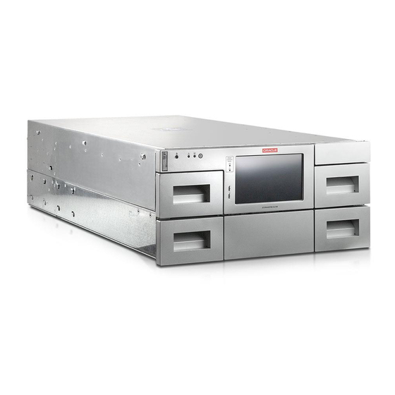
Chapter 1 Base Module Illustration Legend: 1 - Base module (Module 1) 2 - Expansion module (Module 2) 3 - Left cartridge magazines 4 - Right cartridge magazines 5 - Front control panel 6 - Mailslot Figure 1-2 Base Module and Expansion Modules (Rear View) Illustration Legend: 1 - Base module (Module 1 label is on the rear panel of the module) 2 - Expansion modules (a label with the module number is on the rear panel) -
Page 18: Expansion Module
Modules below it. • Base Module Chassis Removal and Replacement (FRU) The entire Base Module can be removed and replaced by Oracle service. Expansion Module An Expansion Module provides additional cartridge storage and tape drive capacity. You can install up to 14 Expansion Modules below the Base Module. -
Page 19: Mailslot
• Expansion Module Chassis Removal and Replacement (FRU) The entire Expansion Module is a FRU that can be removed and replace by Oracle service. Mailslot The mailslot imports and exports cartridges without interfering with robot operations. It is often referred to as a cartridge access port (CAP) in other StorageTek libraries. -
Page 20: Remote Interface
Chapter 1 Remote Interface Related Topics • Robot Module Removal and Replacement The Robot Module is a CRU located at the top of the Base Module. • Unlock the Robot Unlock the robot before operating the library. • Lock the Robot Lock the robot if removing or replacing the robot, moving the library, or preparing the library for shipment. -
Page 21: Front Touch Screen
You can click the Home button in the upper-left of the Status bar at anytime to return to the home screen. Library Specifications Use library specifications to help plan how to implement the SL150 library. These include component weights, dimensions, power requirements, and tape cartridge capacity. -
Page 22: Weights And Dimensions
73 cm (28.75 in) 3.4 kg (7.5 lbs) Note: You can install the SL150 in a rack with front to rear rail spacing from 457 mm (18 inches) to 902 mm (35.5 inches). Table 1-2 Component (Unpackaged) Weights and Dimensions... -
Page 23: Power Requirements
13.7 cm (5.4 in) 8.25 cm (3.25 in) 61.6 cm (24.25 in) 0.9 kg (1.9 lbs) Power Requirements Power usage for the SL150 depends on the components installed. Component Idle (W) Steady State Maximum (W) Base module (one power supply) -
Page 24: Networking And Host Communication
Base Module plus 13 Expansion Modules Base Module plus 14 Expansion Modules Networking and Host Communication The SL150 supports IPv6. The library has requirements when selecting a switch and configuring a SAN. • IPv6 Network Address Support • Selecting a Switch that Uses Power Over Ethernet (POE) •... -
Page 25: Ipv6 Network Address Support
• SAS-2 and SAS-3 Configuration Issues The SAS driver for Solaris 10 (Update 8 and later) and Solaris 11 (11.1 and later) disrupts communications between Oracle Solaris and common tape backup applications. IPv6 Network Address Support The dual-stack network configuration supports both IPv4 and IPv6. -
Page 26: Software That Supports The Sl150
ACSLS manages all library operations, efficiently sharing library resources with any ACSLS-enabled application, allowing centralized library control across multiple StorageTek libraries. To use ACSLS, you must set the SL150's Drive Element Addressing mode to Installed Drives Only. ACSLS Version Description Minimum level to support the SL150 8.3 patch 2... -
Page 27: Service Delivery Platform 2 (Sdp2)
STA tracks mounts, dismounts, and media usage within your tape library system. STA requires a dedicated server. Oracle recommends that you place the STA server on the same subnet as the library to improve SNMP UDP reliability. To set up communications between the STA server and the libraries, you must perform some configuration procedures on the libraries and some on the STA server. -
Page 28: Sl150 Marketing Part Numbers
SL150 Marketing Part Numbers SL150 Marketing Part Numbers Use marketing part numbers when ordering SL150 components. All drives listed are half-height. Oracle recommends a maximum SAS cable length of six meters. The FC cables are multimode (50-micron) fiber-optic cables that connect Fibre Channel devices. - Page 29 Chapter 1 SL150 Marketing Part Numbers Part Type Description Initial Order Part Number Upgrade Part Number FC Cable LC-LC, 50/125/ duplex, riser, 2 CABLE10800308-Z-A CABLE10800308-Z meter FC Cable LC-LC, 50/125/ duplex, riser, 10 CABLE10800310-Z-A CABLE10800310-Z meter FC Cable LC-LC, 50/125,OM4, 50 meter,...
-
Page 30: Configuration And Ordering Examples
Chapter 1 SL150 Marketing Part Numbers Part Type Description Initial Order Part Number Upgrade Part Number Power Cable Jumper, 1 m, straight 333U-10-10-C14 PWRCORD10187055-Z IEC60320-2-2 Sheet E(C14)plug, right angle IEC60320-1-C13 connector, 10A. 250 VAC Power Cable Argentina, 2.5 m, IRAM207... -
Page 31: Order Media And Labels
Chapter 1 SL150 Marketing Part Numbers Order Media and Labels You can order tape cartridges and labels from Oracle or third-party vendors. • Call 1.877.STK.TAPE to order media from your local reseller or to obtain media pre-sales support. • E-mail: tapemediaorders_ww@oracle.com See the tape media area on the Oracle website for additional information. -
Page 32: Install The Library
Install the Library The SL150 library installs into a standard 19-inch rack. You must install the Base Module first, and then install any Expansion Modules below it. Note: These installation instructions use the Sun Rack II (a standard Oracle 19- inch rack). -
Page 33: Gas Limit Recommendations
Chapter 2 Verify the Site Meets Environmental Requirements • Operating: +10° to +40°C (+50° to +104°F) • Non-operating -40° to +60°C (-40° to +140°F) Relative Humidity: • Operating: 20% to 80% (40% to 50% recommended) non-condensing • Non-operating: 10% to 95% non-condensing Airborne Contaminants Limits Maintain airborne contaminate levels below the limits to prevent equipment damage. -
Page 34: Positive Pressurization And Ventilation - Hot Aisle Containment System (Hacs)
System (HACS) Adequate airflow prevents equipment damage. When installing the SL150 in an HACS environment, the system must maintain adequate air flow from the cold to hot aisle. Ensure that there is no turbulent air directed at the installed equipment which may reduce the cooling capability of the cold aisle supply air. -
Page 35: Prepare The Rack
(see Figure 2-1). The power supply outlets are on the right side of the SL150 library. Refer to the rack and power distribution unit documentation for instructions to install the PDU • To provide access during installation of a library module, remove the front door from the rack. -
Page 36: Unpack And Acclimate The Library
Chapter 2 Unpack and Acclimate the Library Illustration Legend: 1 - Power Distribution Unit (PDU) Unpack and Acclimate the Library Carefully unpack components and acclimate the library to the installation environment to prevent equipment damage. Transport the packaged unit to the staging area. Use a pallet jack to transport the Base Module. -
Page 37: Unpack The Base Module Accessory Kit
Chapter 2 Install the Base Module Related Topics • Base Module The Base Module contains the main hardware components of the library. One Base Module is required per library. Unpack the Base Module Accessory Kit Verify that the Base Module kit contains the correct components before installation. •... -
Page 38: Install The Base Module Back Rails
Chapter 2 Install the Base Module Install the Base Module Back Rails The back rails will connect to the front rails and support the module. Install the back rails before the front rails. Parts Required Back rails (1 left, 1 right) Two Mounting blocks Two 8–32 X 5/8 screws Figure 2-3... -
Page 39: Install The Base Module Front Rails
Chapter 2 Install the Base Module Figure 2-4 Back Rails Installed Locate where you will mount the Base Module within the rack, allowing space for Expansion Modules (use the rail installation template as necessary). Verify that the rails will reside with a single U boundary. Do not mount the block with the pins straddling a U boundary. -
Page 40: Connect The Base Module Front Rail To The Back Rail
Chapter 2 Install the Base Module Parts Required Front rails (1 left, 1 right) Two Mounting blocks Two 8–32 X 5/8 screws Complete the following tasks to install the front rails: • Connect the Base Module Front Rail to the Back Rail •... -
Page 41: Verify The Installation Of The Base Module Front Rail
Chapter 2 Install the Base Module Position the mounting block behind the rack stile in the second U of the three U span. See Figure 2-6. You might need to flex the front of the rail away from the rack stile while positioning the mounting block. Figure 2-6 Mounting Block for Front Rail (Right Rail Shown) Illustration Legend:... -
Page 42: Install The Clip Nuts (Square Hole Racks Only)
Chapter 2 Install the Base Module Figure 2-7 Rails Installed - Front View Install the Clip Nuts (square hole racks only) Racks with square holes require a clip nut and a 10–32 X 5/8 screw. The square clip nut is placed on the inside of the rack stile. Figure 2-8 Clip Nut Location for the Base Module Illustration Legend:... -
Page 43: Mount The Base Module
Chapter 2 Install the Base Module Tip: For better access to compress the spring, position the clip nut tabs horizontally and seat the edge toward the outside of the stile. See Figure 2-8, callout 4. Compress the other edge of the clip nut and seat it in the hole. A small flat blade screwdriver can simplify the compression. -
Page 44: Remove The Cartridge Magazine With The Hex Key
Chapter 2 Install the Base Module Illustration Legend: 1 - Front Tab 2 - Center Tab 3 - Bottom Tab 4 - Rear Tab Grasp the module along the sides and lift the back above the rack rails. Never lift the module by the front control panel or the tape drive. -
Page 45: Remove The Cable Clip In The Base Module
Chapter 2 Install the Base Module Pull the magazine a short distance out of the library. Remove the hex key and store it for future use. Support the bottom of the magazine with your other hand during removal. Pull the magazine out of the module, and set it aside. Note the orientation of the magazine. -
Page 46: Install The Expansion Module
Chapter 2 Install the Expansion Module Install the Expansion Module Install up to 14 Expansion Modules below the Base Module to increase drive and cartridge capacity. Installing the Expansion Module involves the following tasks: • Unpack the Expansion Module Accessory Kit •... -
Page 47: Unpack The Expansion Module Accessory Kit
Chapter 2 Install the Expansion Module Unpack the Expansion Module Accessory Kit Check that the Expansion Module kit contains the correct components. • Back rails • 10–32 clip nuts (used in racks with square holes) • Assorted screws: – 10–32 X 5/8 screws (used with clip nuts and racks with 10-32 threaded holes) –... -
Page 48: Remove The Library Floor
Chapter 2 Install the Expansion Module Remove the Library Floor Remove the library floor to add an Expansion Module. Figure 2-13 Library Floor Removal from the Base Module Illustration Legend: 1 - Floor Finger Holds 2 - Floor Lock (Improved Floor Design) If you are upgrading an existing library, power down the library and verify that you have locked the robot. -
Page 49: Install Clip Nuts For The Expansion Module (For Square Hole Racks Only)
Chapter 2 Install the Expansion Module Install Clip Nuts for the Expansion Module (for square hole racks only) If using a rack with square holes, you must install clip nuts to secure the module. If the rack has threaded holes, skip to Prepare the Expansion Module by Removing the Cartridge Magazines. -
Page 50: Prepare The Expansion Module By Removing The Cartridge Magazines
Chapter 2 Install the Expansion Module Make sure the clip nuts are parallel (in the identical mounting hole). Prepare the Expansion Module by Removing the Cartridge Magazines Remove the cartridge magazines to access the mounting holes of the Expansion Module. Figure 2-15 Magazine Latches Illustration Legend:... -
Page 51: Floor Secured
Chapter 2 Install the Expansion Module Insert the rear edge of the floor into the grooves at the bottom of the module. Push the floor in and engage the rear floor tab with the module slot (see Figure 2-16). Push the floor in and seat the floor clip in each magazine bay (see Figure 2-17). -
Page 52: Mount The Expansion Module
Chapter 2 Install the Expansion Module Illustration Legend: 1 - Floor Clip 2 - Floor Mount the Expansion Module The Expansion Module mounts to the bottom of the module already in the rack. With two people, lift the module to the bottom of the installed module. Grasp the module by the sides. -
Page 53: Install The Rear Rails For The Expansion Module
Chapter 2 Install the Expansion Module 2 - Tall Metal Part with Sharp Edges 3 - Flange (Long Section) Figure 2-19 Alignment Tab Seated Illustration Legend: 1 - Tab Seated in Slot 2 - Slot in Magazine Bay Install the Rear Rails for the Expansion Module The rear rails secure the Expansion Module to the rear of the rack. -
Page 54: Secure The Expansion Module To The Rack Front
Chapter 2 Install the Expansion Module Illustration Legend: 1 - Clip Nut 2 - Rear Rail Push the back rail against the rack vertical rail. Secure the back rail to the rack vertical rail with a screw. Use a 10-32 screw for a rack with square holes (the screw mates with a clip nut). -
Page 55: Install The Hook And Loop Strap
Chapter 2 Install the Expansion Module Figure 2-21 Expansion Module ID Label Illustration Legend: 1 - Module Label 2 - Horizontal Scribe Line 3 - Vertical Scribe Line Install the Hook and Loop Strap The hook and loop strap mounts to the rear of the module and assists in cable management. -
Page 56: Install Power Supplies And Tape Drives
Figure 2-23 SL150 Library Rear View Illustration Legend: 1 - Tape Drive Filler 2 - Power Supply Filler... -
Page 57: Tape Drive Tray
Chapter 2 Install Power Supplies and Tape Drives Figure 2-24 Power Supply Illustration Legend: 1 - Power Supply Indicators 2 - Power Supply Latch Figure 2-25 Tape Drive Tray Illustration Legend: 1 - Drive Indicators 2 - Port Indicators (HP drives only) 2-26... -
Page 58: Remove The Power Supply Slot Cover
4 - Thumbscrew (One on Each Side of the Tray) Related Topics • Tape Drives Tape drives read and write data on tape cartridges. The SL150 supports LTO half-height SAS and FC drives. • Power Requirements Power usage for the SL150 depends on the components installed. -
Page 59: Remove The Drive Slot Cover
Chapter 2 Install Power Supplies and Tape Drives Connect a power cord to the power supply receptacle and a receptacle on the rack power strip. Gather cord slack to the outside of the library and wrap the hook and loop strap(s) around the cord. -
Page 60: Cable The Library
Chapter 2 Cable the Library Remove the drive tray from the shipping carton. Handle the drive tray by the rear corners (close to the thumbscrews) and the bottom of the tray. Avoid contact with the top cover of the actual tape drive. Grasp the rear corners of the drive tray and guide the front of the drive tray into the library drive slot. - Page 61 Chapter 2 Cable the Library These Output Ports: Connect to: Base Module Output Port 2 Module 2 Controller Input Port Base Module Output Port 3 Module 3 Controller Input Port Base Module Output Port 4 Module 4 Controller Input Port Base Module Output Port 5 Module 5 Controller Input Port Base Module Output Port 6...
-
Page 62: Connect Cables To The Drives And Power Supplies
Chapter 2 Cable the Library Figure 2-27 Cabling the Expansion Modules Connect Cables to the Drives and Power Supplies Connect the power cables to the power supplies and FC/SAS cables to the drives. For each power supply, connect the power cord to the power supply and the power distribution unit in the rack. -
Page 63: Connect The Network Port
Chapter 2 Unlock the Robot For each installed tape drive, connect the interface cable (FC or SAS) to the tape drive interface port. Attach a label indicating the tape drive position in the module and port to ensure proper connection after a servicing the drive. Note: The interface port is located on the left side of the drive tray assembly (as viewed from the rear of the library). -
Page 64: Unlock The Knob-Type Robot Lock
Chapter 2 Unlock the Robot Unlock the Knob-type Robot Lock Unlock the robot by twisting the knob at the back of the Base Module. The knob-type robot lock is on newer hardware versions. Turn the knob clockwise until it clicks into place. The pointer on the knob should point past the black, unlocked padlock icon:. -
Page 65: Apply Power To The Library
Chapter 2 Apply Power to the Library Verify that the white unlocked padlock icon is visible in the small window. Secure the lock assembly by tightening the captive screw. Apply Power to the Library Powering on the library starts initialization. Apply power to the library after you have completely installed all hardware components. -
Page 66: Configure The Library: Login With The Default Admin
Chapter 2 Configure the Library After Powering-on for the First Time • Configure the Library Step 6 of 6: Review and Apply Initialization Settings • Configure the Library: Finish the New Configuration Configure the Library: Login with the Default Admin The initial library configuration requires you to login with a default admin account. -
Page 67: Configure The Library Step 2 Of 6: Configure The Network Port 1
Chapter 2 Configure the Library After Powering-on for the First Time If an error message appears, click the keyboard button to access the keyboard screen and clear the password field before you tap any key. Repeat the previous steps as necessary to correct the password entries. Tap Next. -
Page 68: Configure The Library Step 3 Of 6: Set The Library Date And Time
Chapter 2 Configure the Library After Powering-on for the First Time Option 2: Configure Network Port 1 with an IPv6 Address" Use the Configure IPv6 list to select DHCPv6, Stateless (SLAAC), or Static. • If you select the DHCPv6 option, for a successful startup, DHCPv6 must be running on your network. -
Page 69: Configure The Library Step 5 Of 6: Configure The Mailslot, Reserved Slots And Volume Label Format
Chapter 2 Configure the Library After Powering-on for the First Time Select the Drive Element Addressing Mode from the list. The options are: Address All Drive Slots (Recommended) All drives, including empty drive slots, are assigned a sequential SCSI element address which is always reported to attached hosts. -
Page 70: Configure The Library Step 6 Of 6: Review And Apply Initialization Settings
Expanded (19 slots) Set the system reserved slots. System reserved slots are storage slots in the SL150 library typically used to house cleaning tapes or diagnostic tapes. Use the System Reserved Slots list to select the desired number of slots (see... -
Page 71: Configure The Library: Finish The New Configuration
Chapter 2 Run a Self-Test Caution: Do not manually remove a cartridge magazine while the library is starting up. You could damage the robot or other internal components. Only manually remove the magazine when the library is operational and offline. After the restart completes, the Home screen appears on the touch screen. -
Page 72: Stopping A Self-Test
Chapter 2 Run a Self-Test • Full Self Test — a thorough test that moves a tape to every slot and to every unoccupied drive compatible with the chosen diagnostic tape. A full test can take significant time depending on the number of modules in the library, so plan accordingly. -
Page 73: Basic User Interface Operations
Basic User Interface Operations Basic operations are common actions used to interact with the user interface, such as logging in, reordering columns, or printing a table. • Log In to the Remote Interface • Log Out of the Remote Interface •... -
Page 74: Export A Table As A Spreadsheet
Chapter 3 Export a Table as a Spreadsheet Select Reorder Columns..., and then use the up and down arrows to order the columns. Related Topics • Export a Table as a Spreadsheet Export an .xls file for any of the tables found in the remote interface. Use a spreadsheet application to analyze the exported table data. - Page 75 Chapter 3 Print a Table • Export a Table as a Spreadsheet Export an .xls file for any of the tables found in the remote interface. Use a spreadsheet application to analyze the exported table data.
-
Page 76: Configure The Library
Configure the Library Update the library configuration using the wizard, update library firmware, and manage the library's certificate. • Run the Configuration Wizard – Configure the Network Interfaces – Set the Library Date and Time – Configure Library Settings – Partition the Library –... -
Page 77: Configure The Network Interfaces
Chapter 4 Run the Configuration Wizard Note: You cannot configure the network interfaces and encryption simultaneously. Configure the Network Interfaces Configure the library's two local area network interfaces for communication to external applications. • Network Port 1 — connects browser-based, remote user interface clients to the interface server on the library. -
Page 78: Configure Network Port 2
Note: Do not configure Port 2 for any other use than with LME, otherwise you may encounter issues. If you are not using LME, Oracle recommends that you leave Port 2 set to the defaults. See Behavior of Library Port 1 and Port 2 with LME for more information. -
Page 79: Set The Library Date And Time
Chapter 4 Run the Configuration Wizard Note: You must configure Port 2 with a different subnet than Port 1 to create a secure and private network connection to pass the encryption keys between the library and the OKM cluster. From the "Configure IPv4" drop-down list select either: •... -
Page 80: Partition The Library
– You are using ACSLS. – You are upgrading an SL150 library that does not currently assign addresses to empty drive bays. Selecting Address Only Installed Drives retains the current addresses and assigns the next address in sequence to the new drive. -
Page 81: Access The Partitioning Screen
Chapter 4 Run the Configuration Wizard Requirements: • Maximum of eight partitions (code versions before 2.0 only support two partitions) • Each partition must have it's own bridged drive • Each partition must have at least one magazine • Mailslot must be closed, locked, and empty before changing the partitioning configuration Partitioning Tasks: •... -
Page 82: Assign Resources To The Partition
Chapter 4 Run the Configuration Wizard Assign Resources to the Partition Resources assigned to a partition can only be used by that partition. Assign each partition at least one bridged drive and one cartridge magazine. Pre-requisites: • You are in the partitioning wizard (if not, see Access the Partitioning Screen). -
Page 83: Configure Library Managed Encryption (Lme)
Obtain Information from OKM Configure the SL150 as an agent within OKM and record the information. Have the OKM administrator use the OKM GUI to create an SL150 library agent and then record the following information to use in the SL150 configuration: •... -
Page 84: Verify The Sl150 Agent Is Enrolled
Confirm the library is enrolled as an agent in OKM. After confirming the changes within the Configuration Wizard, have the OKM administrator go to the OKM GUI and verify that the SL150 agent now shows "Enrolled: True". See the OKM documentation for more information. -
Page 85: Identify Current Firmware Versions
In the Patch Search Results table, click a row. A button bar displays. Click Read Me to confirm the firmware version. For drive firmware, make sure it is intended for the SL150 library. Note the firmware release level. Scan the drive firmware Read Me file for lines like the... -
Page 86: Verify The Download
MD5 or SHA-1 digest value of the downloaded file, and compare the result to the corresponding MD5 or SHA-1 value saved in your text file. You can use digest (Oracle Solaris) and dgst (Linux). Microsoft offers a commandline File Checksum Integrity Verifier utility (fciv.exe) as a free download from http://support.microsoft.com/kb/841290. -
Page 87: Manage The Library's Ssl/Tls Certificate For Https
Chapter 4 Manage the Library's SSL/TLS Certificate for HTTPS Click Firmware in the left menu. To roll back the library firmware, click Revert If the library has been operating normally and if its contents have not changed, check the Bypass audit for a faster restart ... check box. Click OK to restart the library and activate the old firmware. -
Page 88: Export Certificate Signing Request (Csr) File
Chapter 4 Configure Accessibility Settings Export Certificate Signing Request (CSR) File Export the file required to send to the certifying authority (CA). Click Configuration in the left navigation area of the GUI. Click the Certificate tab, and then click Export CSR Click Download. -
Page 89: Set Automatic Screen Refresh
Chapter 4 Set Automatic Screen Refresh You can navigate between the different parts of an SL150 user interface screen, menu, or list using the tab and arrow keys on the keyboard. You select interface elements by pressing the Return key on the keyboard. -
Page 90: Users
Service — a special role for service technicians. The service user has all the privileges of an administrator except for managing users. When you require the assistance of an Oracle service representative, you can create a log-in account for the service person and assign the account to the Service user. -
Page 91: Reset Another User's Password
Chapter 5 Reset Another User's Password In the Old Password field, enter your current password. In the Password field, enter your new password. In the Verify Password field, re-enter your new password. Note: The password must be at least eight characters long and contain one or more numeric or special characters. -
Page 92: Remove A User
Chapter 5 Remove a User Note: Once the account is set up, users can choose their own passwords. Related Topics • User Roles and Access A user's role determines their access to library functions. • Change Your Password Change your password at any time. Remove a User The administrator can delete users, removing their access to the library. -
Page 93: Tape Cartridges (Media)
Tape Cartridges (Media) Tape cartridges store data. Each tape cartridge must be compatible with at least one tape drive in the library. Note: LTO-5, 6, and 7 drives can read two generations back and write one generation back. LTO-8 drives can read and write one generation back. For best capacity and performance, always use cartridges of the same generation as your drives. -
Page 94: Media Labels
Chapter 6 Media Labels Media Validation • Add a Drive to the Media Validation Pool • Remove a Drive from the Media Validation Pool • Start a Media Validation • Manually Cancel a Validation in Progress • Media Validation Type •... -
Page 95: Tape Cartridge Types
The M8 cartridge is an LTO7 cartridge with increased storage capacity. • Support for Non-Standard Label Formats The SL150 can accommodate non-standard LTO labels to support proprietary labeling schemes. Tape Cartridge Types There are three cartridge types: data, cleaning, and diagnostic. -
Page 96: Support For Non-Standard Label Formats
LTO labeling format, a few use proprietary labeling schemes to track volumes. If you use such an application, you can, in most cases, configure the SL150 to automatically translate between the physical labels on your cartridges and the logical label format that the application uses internally. -
Page 97: Prepare Diagnostic, Cleaning, And Data Tape Cartridges
Diagnostic cartridges are specially labeled data cartridges used for testing library robotics and drives. You can purchase diagnostic cartridges or you can create them by applying an Oracle-supplied diagnostic label to any available, blank LTO tape. Oracle recommends that you have a diagnostic tape on hand during system configuration and at all times thereafter, if possible. -
Page 98: View A List Of Tape Cartridges
Chapter 6 View a List of Tape Cartridges Figure 6-1 Correct Label Orientation 1 - Write Protect Switch 2 - Cartridge label correctly applied (barcode side down/character side up) Related Topics • Media Labels The library identifies cartridges by the barcode label attached to the front of the cartridge. -
Page 99: Guidelines For Handling Tape Cartridges
Chapter 6 Guidelines for Handling Tape Cartridges • Suspect — the last time the tape was unloaded, the drive presented one or more "suspect" tape alerts. These alerts are shown in the Tapes table. Guidelines for Handling Tape Cartridges Properly handle tapes to prevent damage and data loss. Caution: Improperly handling tape cartridges can cause loss of data or damage the library. -
Page 100: Clean The Tape Cartridge Exterior
Chapter 6 Guidelines for Handling Tape Cartridges • Liquid in the tape cartridge • Labels not firmly attached, or that extend over the tape cartridge edge • Incorrect media type. The cartridge type must be supported by the drives in the library. -
Page 101: Load The Magazines (Bulk Loading)
Chapter 6 Load the Magazines (Bulk Loading) out of its protective wrapping until you are ready to use it. Use the tear string (not a sharp instrument) to remove the wrapping. Related Topics • Verify the Site Meets Environmental Requirements Make sure the site meets environmental requirements to prevent equipment damage. - Page 102 Chapter 6 Load the Magazines (Bulk Loading) Optionally, populate the reserve slots with diagnostic and/or cleaning cartridges (see Determine the Required Number of Reserved System Slots). Place the diagnostic cartridge at the top (if using), followed by the cleaning cartridges. The following are all valid reserve slot configurations: When inserting the cartridges into the magazine, orient the cartridge with the hub down and the label on the open side of the magazine.
-
Page 103: Load The Remaining Magazines
Chapter 6 Load the Magazines (Bulk Loading) Load the Remaining Magazines Load the rest of the magazines in the library with tape cartridges. Note: If using the 19-slot mailslot configuration, leave the right Base Module magazine empty. Slide each magazine out of the enclosure, supporting the underside with one hand. -
Page 104: Import Or Export Cartridges Using The Mailslot
In a partitioned library, you must assign the mailslot to a partition before exporting or importing tapes. For information on how SCSI hosts handle a shared mailslot, see the SL150 SCSI Reference Guide. Assign the Mailslot Using the Remote Interface Select Library from the left menu. -
Page 105: Import Tape Cartridges
Chapter 6 Import or Export Cartridges Using the Mailslot Import Tape Cartridges Use the mailslot to import tapes into the library. If importing into a partitioned library, assign the mailslot to a partition (see Assign the Mailslot to a Partition). Open the Mailslot. -
Page 106: Close The Mailslot
Chapter 6 Import or Export Cartridges Using the Mailslot • If using the local touch panel: On the Home screen, tap Mailslot. Tap Open Mailslot. If you do not see an Open Mailslot button, the mailslot is incorrectly assigned. Pull the standard mailslot out from the upper-right corner of the Base Module. If using the expanded mailslot, slide out the right magazine in the Base Module, supporting the weight with one hand. -
Page 107: Move Tape Cartridges With The Remote Interface
• Diagnostic Cartridge — may require 1 reserved slot. If you are planning to use a diagnostic cartridge, Oracle recommends that you configure one reserved system slot to hold it. This insures that it is always available when needed. But if storage space is at a premium, you can also import the diagnostic cartridge from the mailslot as needed. -
Page 108: Determine The Number Of Cleaning Cartridges
If using host-managed cleaning: the number of cleaning cartridges required depends on your partitioning configuration. For a non-partitioned library, Oracle recommends that you provide two, new, LTO universal (CU) cleaning cartridges placed into storage slots. For a partitioned library, Oracle recommends that you provide two, new, LTO universal (CU) cleaning cartridges per partition. -
Page 109: Monitor Cleaning Cartridges Using The Remote Interface
Chapter 6 Manage Expired Cleaning Cartridges A cleaning cartridge expires when a drive determines the cartridge is no longer usable. When the drive identifies an expired cartridge, it notifies the library. The library dismounts the cartridge, flags it as expired, and alerts the remote interface. Remove expired cleaning cartridges and replace them with new one. -
Page 110: Replace Expired Cleaning Tape Using The Host Application
Chapter 6 Media Validation • Replace Expired Cleaning Tape Using the Host Application Use the host-application to remove expired cleaning tapes that are within host- managed storage slots. Replace Expired Cleaning Tape Using the Host Application Use the host-application to remove expired cleaning tapes that are within host- managed storage slots. -
Page 111: Add A Drive To The Media Validation Pool
Chapter 6 Media Validation • Start a Media Validation • Manually Cancel a Validation in Progress • Media Validation Type • Effects of a Library Restart on Media Validation • Why Aren't the Media Validation Drives Showing in STA? Add a Drive to the Media Validation Pool Add IBM LTO6 or higher drives to the pool to dedicate them for media validation. -
Page 112: Start A Media Validation
Chapter 6 Media Validation Start a Media Validation Evaluate a tape cartridge by reading data previously written on the tape. The tape is considered valid if the drive does not encounter errors during the read. Caution: Repeated use of media validation will reduce the life of the tape. Do not use this feature frequently. -
Page 113: Media Validation Type
If the SL150's Drive Element Addressing mode is set incorrectly, the media validation drives will not appear in the STA application. You must set the SL150 to Address All Drive Slots mode if using STA and media validation. If the mode is Address Only Installed Drives, the media validation drives will not show within STA. -
Page 114: Tape Drives
Tape Drives Tape drives read and write data on tape cartridges. The SL150 supports LTO half- height SAS and FC drives. About Tape Drives • Supported Tape Drives • Bridged Tape Drives Drive Encryption • Library Managed Encryption (LME) •... -
Page 115: Bridged Tape Drives
You must connect the bridged drive to an HBA supporting multiple LUNs (also referred to as LUN scanning). The SL150 Library uses a single SCSI ID and two logical unit numbers (LUN). LUN 0 controls the tape drive and LUN 1 which is configured as a SCSI medium changer device controls the robotics. -
Page 116: Behavior Of Library Port 1 And Port 2 With Lme
Port 1 will send SDP-2 traffic. Since the library will only send LME (OKM) traffic through Port 2, this requires the Oracle Service tool SDP-2 to now be connected to Port 1 when LME is enabled on Port 2. -
Page 117: View Drive Information
• Unloading Related Topics • Tape Drives Tape drives read and write data on tape cartridges. The SL150 supports LTO half-height SAS and FC drives. Configure Drive Cleaning Manage drive cleaning in one of three ways: library-managed, host-managed, or manually. -
Page 118: Enable Library-Managed Drive Auto Cleaning
Many storage-management and backup applications can manage drive cleaning (such as Oracle Secure Backup, Symantec NetBackup, IBM Tivoli Storage Manager, and others). A cleaning cartridge must be available in a storage slot the host application controls. -
Page 119: Configure Automatic Cleaning In Oracle Secure Backup During Drive Setup
From the Administration Console, select Media and Device Management. Select Device Monitor, and then select Drives. In the Drive Status pane, select an SL150 drive and then open the Actions menu. Select the Set Cleaning Frequency parameter, and set the value to 0 (zero). This tells NetBackup to clean drives in response to Tape Alerts. -
Page 120: Set Up Symantec Backup Exec Drive Cleaning
Chapter 7 Configure Drive Cleaning If you have already added the drives to your NetBackup configuration, run the command /usr/openv/volmgr/bin/tpclean/tpclean -F drive_name 0, where: • drive_name is the name that was assigned to the drive when it was added to the NetBackup device configuration. -
Page 121: Set Up Commvault Drive Cleaning
Chapter 7 Configure Drive Cleaning Select Devices from the navigation tree. In the Devices table, right-click on one of the SL150 tape drives, and select Properties from the context menu. In the Properties window, select the Advanced tab. In the Device Configuration area of the Advanced tab, under CDI settings, select SCSI Commands: Sends explicit SCSI commands to tape devices. -
Page 122: Restart A Drive
Make sure that the proper device driver is installed, if applicable. Use Windows Update to obtain the driver for an IBM tape drive. Download the driver from the HP website, if needed. For example, Oracle has qualified the HP LTO-5 and LTO-6 drives with Windows driver 3.5.0.0. - Page 123 Chapter 7 Update the Drive Firmware Log in to the remote user interface as an administrator. Take the library offline (see Place the Library Online or Offline). Select Firmware in the left menu. Click the Drive Firmware tab. Click Upgrade Drive Firmware Click on the table entries to select the drive(s) that you want to update (hold down the Shift key to select multiple drives).
-
Page 124: Monitor The Library
Monitor the Library Monitor library operations for component failures and operational problems. • View the Library Screen • View the Library State • View User and Host Activity • Configure Simple Network Management Protocol (SNMP) • Enable or Disable the Service Delivery Platform (SDP2) •... -
Page 125: View The Library State
Chapter 8 View the Library State View the Library State The status bar at the top of the interface displays library health, which represents the combined state of every component in the library. • Operative — the library is fully operational. •... -
Page 126: View User And Host Activity
Chapter 8 View User and Host Activity Figure 8-2 LEDs on Rear of Base Module Figure 8-3 LEDs on Rear of the Expansion Module Determine the Possible Cause of a Degraded or Failed Library State Click the library health in the status bar to display a list of faults. Click on the Degraded or Failed health state in the status bar. -
Page 127: Configure Simple Network Management Protocol (Snmp)
Chapter 8 Configure Simple Network Management Protocol (SNMP) Configure Simple Network Management Protocol (SNMP) Network management applications can monitor the library using the Simple Network Management Protocol (SNMP). The library's SNMP agent can automatically send traps to alert network management stations of faults and configuration changes. -
Page 128: Snmp Traps
Community Name — A 31-character, alphanumeric password or phrase. Do not use factory-set default community names or obvious strings like public and private. SNMP Traps The SL150 returns a finite set of SNMP traps. Table 8-1 SNMP Trap Levels Trap Level Description... -
Page 129: Configure An Snmp Trap Recipient
Enable or disable SNMP using the remote interface. • SNMP Traps The SL150 returns a finite set of SNMP traps. Download the Management Information Base (MIB) The MIB defines entities and OIDs used in SNMP. Use the remote interface to download the MIB. -
Page 130: Enable Or Disable The Service Delivery Platform (Sdp2)
Chapter 8 Enable or Disable the Service Delivery Platform (SDP2) Enable or Disable the Service Delivery Platform (SDP2) SDP2 can send automated service requests (ASR) when the library encounters an issue. Enable or disable SDP2 from the remote interface. From the remote interface, select SNMP in the left menu. Click the SDP2 is Enabled/Disabled drop-down. -
Page 131: Configure Email Recipients
Chapter 8 Configure Email Notifications • From Name — The name that should appear in the sender field of the email. The default is "Library Alert". • From Email — The email address that should appear in the sender field of the email. -
Page 132: Service The Library
Perform routine library maintenance to correct library issues. WARNING: Oracle's StorageTek SL150 Modular Tape Library contains a Class-1 laser, as defined by IEC 60825-1 Ed. 2 (2007). Use of controls or adjustments or performance of procedures other than those specified herein may result in hazardous radiation exposure. -
Page 133: Power On The Library
Chapter 9 Power On the Library Power On the Library Power on the library from the front of the Base Module. Gain physical access to the library. When the library is off, the browser-based user interface is not running, so you cannot power the system on remotely. Verify the robot is unlocked (if not, see Unlock the Robot). -
Page 134: Controlled Power-Down From The Interface
Chapter 9 Power Off the Library Controlled Power-Down from the Interface Always use the remote interface to power down the library when possible. Stop any host activity. From the remote interface, click the power button in the upper-left, and then select Power Down Library. -
Page 135: Lock The Knob-Type Robot Lock (New Version)
Chapter 9 Power Off the Library • Lock the Robot for Shipment within a Rack Lock the robot into place when shipping the library installed in the rack. Lock the Knob-type Robot Lock (new version) The newer lock style is a knob that you twist. To lock, turn the knob counter-clockwise until it clicks into place. -
Page 136: Restart The Library
Chapter 9 Restart the Library Rotate the lock assembly counterclockwise 180 degrees, and slide the long tab into the slot at left. Verify a red locked padlock icon is visible in the small window. Secure the lock assembly by tightening the captive screw. The robot is now locked. -
Page 137: Move The Library Rack
Chapter 9 Move the Library Rack From the remote interface, select Library in the left menu. From the Library drop-down menu , select Audit Library. Optionally, select Set the Library back Online ... To take the library offline, start the audit, and close the dialog, press OK. If you did not check the Set the Library back Online ... -
Page 138: Enable The Locate Light
Diagnose a Browser-Based User Interface Problem The browser level and type may cause issues with the remote interface. If you have problems with a browser, try a different browser. Check the SL150 firmware release notes for known incompatibilities. If you start to have problems with a browser that used to work, check for recent changes to the browser configuration: •... -
Page 139: Diagnose A Library Problem
Chapter 9 Troubleshoot the Library Diagnose a Library Problem The health table, health log, and self-tests help diagnose library problems. • Diagnose Why You Cannot Login to the Remote Interface • Use the Health Table to Diagnose the Issue • Check if a Fault is Closed in the Health Log •... -
Page 140: Check If A Fault Is Closed In The Health Log
Chapter 9 Troubleshoot the Library – If Drive Auto Clean is enabled — If the drive listed in the suspected component field is mounted, wait. The library will attempt a cleaning once the tape dismounts. If the fault persists after the tape dismounts, a cleaning cartridge is unavailable or expired. -
Page 141: Locate And Remove A Cartridge Stuck In A Magazine Slot
Chapter 9 Troubleshoot the Library • If you Closed all fault records and still cannot get the library into Operational condition, go to Get Parts and Technical Support, check for relevant knowledge articles, and, if you cannot find a resolution, open a service request. -
Page 142: Save The Health Log To A File
Chapter 9 Troubleshoot the Library If you cannot remove the problem cartridge, stop here. Go to Get Parts and Technical Support, and check for relevant knowledge articles. If you cannot find a resolution, open a service request. If you successfully removed the problem cartridge, remove the source magazine and check the source storage slot for defects. -
Page 143: Restore The Factory Default Configuration
Chapter 9 Troubleshoot the Library take significant time depending on the number of modules in the library, so plan accordingly. Optionally, select Set the Library back Online to automatically bring the library online after the test (the library goes offline to perform the self test) Click OK to start the test. -
Page 144: Sas-2 And Sas-3 Configuration Issues
The SAS driver only allows one device driver to attach per device (sg, sgen, st, and so forth). Users must have every component in the following list to be affected: • Oracle Solaris 10 (Update 8 or later) or Solaris 11 (11.1 and later) • Any SAS-2 or SAS-3 HBA •... -
Page 145: Get Parts And Technical Support
Chapter 9 Get Parts and Technical Support If you want to use Oracle Solaris 10 (Update 8 and later) or Solaris 11 (11.1 and later) and a SAS-2 or SAS-3 HBA, you should use one of the following backup applications: •... -
Page 146: Run A Self-Test
Chapter 9 Run a Self-Test Run a Self-Test A self-test can help troubleshoot library issues and confirm proper installation. Before placing a newly installed or reconfigured library into production, you should run a full self-test. Before running a self-test, verify the following: •... -
Page 147: Replace Components (Crus & Frus)
Robot Module Removal and Replacement • Expansion Module Chassis Removal and Replacement (FRU) • Base Module Chassis Removal and Replacement (FRU) • Validate the Component Installation • Return CRU Components to Oracle • Lock the Robot for Shipment within a Rack 10-1... -
Page 148: Cru Locations
Chapter 10 CRU Locations CRU Locations CRUs include the front control panel, drive tray, robot module, module controller, and power supply. Illustration Legend: 1 - Tape Drive Tray 2 - Robot (in the Base Module) 3 - Module Controller (in the Expansion Module) 4 - Power Supply Drive Tray Removal and Replacement The drive tray is a CRU that can be removed and replaced while the library is online. -
Page 149: Remove The Drive Tray
Chapter 10 Drive Tray Removal and Replacement Figure 10-1 Tape Drive Tray CRU (HP LTO-5) Illustration Legend: 1 - Drive Indicators 2 - Port Indicator (HP SAS and HP LTO-6 FC Drives) 3 - Encryption Indicator and IP Reset Switch (HP drives only) 4 - Thumbscrew (Drive Tray has Two Thumbscrews) Remove the Drive Tray Remove a drive tray for replacement or relocation. -
Page 150: Replace The Drive Tray
Chapter 10 Drive Tray Removal and Replacement Label and then disconnect the cables from the drive tray. Loosen the two green thumbscrews on the drive tray. Grasp the drive tray, pull it out of the slot, and set it on a work surface. Replace the Drive Tray Replacing the drive tray involves unpacking the new tray, installing the tray, and verify the library recognizes the tray. -
Page 151: Install The Drive Slot Cover
Chapter 10 Power Supply Removal and Replacement Identify the tape drive firmware version and upgrade if necessary. See Update Firmware. Install the Drive Slot Cover A drive filler covers an empty drive tray slot. Position the tape drive cover with the spring fingers facing up. Grasp the captive screws and guide the cover into the tape drive slot. -
Page 152: Remove The Power Supply
Chapter 10 Power Supply Removal and Replacement Figure 10-2 Power Supply CRU Illustration Legend: 1 - Power Supply Indicators 2 - Power Supply Latch Remove the Power Supply The power supply resides in a slot in the Base Module or Expansion Module. If the library only has one power supply, power off the library before proceeding (see Power Off the... -
Page 153: Install A Power Supply Slot Cover
Chapter 10 Front Control Panel Removal and Replacement Verify that the OK indicator is active on the power supply. If not, continue to Validate the Component Installation. Install a Power Supply Slot Cover The filler covers an empty power supply slot. Position the cover with the spring fingers facing up. -
Page 154: Remove The Front Control Panel
Chapter 10 Front Control Panel Removal and Replacement Figure 10-3 Rear View of the Front Control Panel Illustration Legend: 1 - Tabs 2 - Jack 3 - Latches Remove the Front Control Panel The front control panel latches into the front of the Base Module. Use care when removing the panel. -
Page 155: Replace The Front Control Panel
Chapter 10 Front Control Panel Removal and Replacement Free the tabs on the top edge of the panel from the module. Rotate the top edge of the panel away from the top of the module about 90 degrees and hold the panel in this position with one hand. Disconnect the ribbon cable plug from the jack located on the circuit card. -
Page 156: Module Controller Removal And Replacement
Chapter 10 Module Controller Removal and Replacement Rotate the front control panel down and press the bottom edge into the Base Module slots. The panel snaps in place. Replace both cartridge magazines. Lock the magazines and audit the library (see "Lock the Magazines and Audit the Library"). -
Page 157: Replace The Module Controller
Chapter 10 Module Controller Removal and Replacement Disconnect the expansion cable plug from the input port on the Module Controller. Disconnect the expansion cable plug from the output port on the Module Controller of a library with a tape capacity of greater than 300 tapes. This action applies to Module 6 through Module 10. -
Page 158: Robot Module Removal And Replacement
Chapter 10 Robot Module Removal and Replacement Insert the failed Module Controller into the ESD packaging. Follow the power on procedures (see Validate the Component Installation). Robot Module Removal and Replacement The Robot Module is a CRU located at the top of the Base Module. The robot must be parked in the Base Module with the robot lock engaged and the thumbscrews loosened before attempting to remove the Robot Module. -
Page 159: Slide Robot Cru Out Of Base Module
Chapter 10 Robot Module Removal and Replacement Slide Robot CRU Out of Base Module The Robot Module slides out of the top-rear of the Base Module. Note: The robot CRU weighs approximately 5 kg (11 pounds). Label the cables connected to the robot CRU as necessary. Disconnect all cables attached to the robot CRU. -
Page 160: Manually Disengage The Robot
Chapter 10 Robot Module Removal and Replacement Turn the gear with your thumb to raise the robot, hold the gear in position with a finger, reposition your thumb, and turn the gear. Repeat as necessary until the robot is at the top of the Base Module. If the robot does not retract, disengage it (see Manually Disengage the Robot). -
Page 161: Cut The Robot Cables
Chapter 10 Robot Module Removal and Replacement • Clean Up After Manually Removing the Robot Cut the Robot Cables To manually remove the robot, you must cut the cables to the robot to allow the Z-platform to move. Make sure the library is powered down. Remove all tape drives from the Base Module. -
Page 162: Clean Up After Manually Removing The Robot
Chapter 10 Robot Module Removal and Replacement Clean Up After Manually Removing the Robot Verify no components are left within the library and that you replace all magazines. Inspect the library floor and remove any debris resulting from the broken robot. Replace all cartridge magazines and tape drives removed during this procedure. -
Page 163: Expansion Module Chassis Removal And Replacement (Fru)
Expansion Module Chassis Removal and Replacement (FRU) The entire Expansion Module is a FRU that can be removed and replace by Oracle service. The Expansion Module is a field-replaceable unit (FRU) and must be serviced by an Oracle service person. Customers should not replace the Expansion Module. -
Page 164: Power Down, Lock The Robot, And Remove Magazines
Chapter 10 Expansion Module Chassis Removal and Replacement (FRU) • Remove Components from the Defective Module Power Down, Lock the Robot, and Remove Magazines You must park and lock the robot before attempting to remove an Expansion Module. Power down the library with the option enabled to prepare the robot for removal. Controlled Power-Down from the Interface. -
Page 165: Remove Operational Expansion Modules Below The Defective Module
Chapter 10 Expansion Module Chassis Removal and Replacement (FRU) Remove Operational Expansion Modules Below the Defective Module To access the defective module, you must remove all modules below it. WARNING: Expansion modules weigh about 19.9 kg (43.9 pounds) with two cartridge magazines, 30 tape cartridges, two tape drives, and two power supplies. -
Page 166: Replace The Expansion Fru Chassis
Chapter 10 Expansion Module Chassis Removal and Replacement (FRU) Remove the functional components as applicable: • Remove the Drive Tray • Remove the Drive Slot Cover • Remove the Power Supply • Remove the Power Supply Slot Cover • Remove the Module Controller Remove the failed Expansion Module. -
Page 167: Install The Remaining Expansion Modules
Chapter 10 Expansion Module Chassis Removal and Replacement (FRU) Tip: When the library capacity is more than 300 cartridges, you will not connect the output port for Module 6 through Module 10 now. You connect the port when installing Module 11 through Module 15. Install the tape drive assembly. -
Page 168: Base Module Chassis Removal And Replacement (Fru)
The entire Base Module can be removed and replaced by Oracle service. The Base Module is a field-replaceable unit (FRU) and must be serviced by an Oracle service person. Customers should not attempt to replace the Base Module. You must... -
Page 169: Lock The Robot And Remove Expansion Modules
Before removing the Base Module, the robot must be parked and locked. All Expansion Modules below the Base must be removed. Removing and replacing the Base Module can only be performed by an Oracle Service representative. Park and Lock the Robot. -
Page 170: Install The Base Module Crus And Expansion Modules
Chapter 10 Base Module Chassis Removal and Replacement (FRU) Grasp the Base Module chassis by the sides and remove it from the shipping carton. If there are no Expansion Modules for this library, install the floor in the Base Module. Install the Floor in the Bottom Expansion Module. -
Page 171: Validate The Component Installation
• Module Controller — Confirm that the library recognizes the module controller (Modules area of the touch screen or Library area of the SL150 remote interface). Run the offline self tests from the remote interface (see Run a Self-Test). -
Page 172: Power Down The Library And Verify Robot Position
Chapter 10 Lock the Robot for Shipment within a Rack Caution: Improper installation of the lock could cause damage during shipment. • Power Down the Library and Verify Robot Position • Install the Shipping Clip Power Down the Library and Verify Robot Position The robot needs to be at the top and front of the Base Module to be locked into place. - Page 173 Chapter 10 Lock the Robot for Shipment within a Rack Illustration Legend: 1 - Opened Shipping Clip 2 - Instruction Tag Squeeze the clip to reduce the clamping force on the shaft and slide the clip toward the hand assembly (see image below). The hand will be contained between the front wall and the clip.
- Page 174 Chapter 10 Lock the Robot for Shipment within a Rack Replace the right magazine in the Base Module and verify the magazine is securely latched. 10-28...
-
Page 175: Slot Mapping And Cartridge Locations
Slot Mapping and Cartridge Locations Each slot in the library has a corresponding address. Addressing can refer to SCSI element ID or library addressing. • Cartridge Slot Addressing • Drive, Mailslot, Power Supply, and Robot Addressing • SCSI Element Addressing •... -
Page 176: Scsi Element Addressing
Hand (Robot) No address SCSI Element Addressing See the SL150 SCSI Reference Guide for more information. Example Library Configurations and Slot Maps Library addressing varies depending on the library configuration. Figure A-1 Non-Partitioned One Module Library, Standard Mailslot, and No Reserved Cells... -
Page 177: Non-Partitioned Two Module Library, Expanded Mailslot, And No Reserved Cells
Appendix A Example Library Configurations and Slot Maps Figure A-2 Non-Partitioned Two Module Library, Expanded Mailslot, and No Reserved Cells Illustration Legend: 1 - Module 1 (Base) 2 - Robot 3 - Power supplies 4 - Tape drives 5 - Standard mailslot 6 - Mailslot expansion 7 - Right magazine front 8 - Left magazine front... -
Page 178: Non-Partitioned 15 Module Library, Standard Mailslot, And Three Reserved Cells
Appendix A Example Library Configurations and Slot Maps Figure A-3 Non-Partitioned 15 Module Library, Standard Mailslot, and Three Reserved Cells Illustration Legend: 1 - Module 1 (Base) 2 - Robot 3 - Power supplies 4 - Standard mailslots 5 - Left magazine front 6 - Right magazine front 7 - Storage slots 8 - Reserved slots (Configurable) -
Page 179: Glossary
Glossary alphanumeric A character or group of characters that identifies a register, a particular part of storage, or some other data source or destination. (A). The robotic assembly that is lowered between the columns of tapes. The arm hangs on four wires from the Z mechanism. The arm includes the hand, the rails the hand rides on, the track motor that moves the hand along the rails, and the KLT card. - Page 180 Glossary cartridge A storage device that consists of magnetic tape on a supply reel in a protective housing. The spine of the cartridge usually contains a label listing the volume identification number. Also called tape, tape cartridge, tape volume, or cassette. cell See slot.
- Page 181 Glossary drive tray tape drive. dynamic host configuration protocol (DHCP) A network protocol that enables a server to automatically assign an IP address to devices on a network. DHCP assigns a number dynamically from a defined range of numbers for a given network. encryption The process of changing data into a form that cannot be read until it is deciphered, protecting the data from unauthorized access and use.
- Page 182 Glossary export The action in which the device places a cartridge into the mailslot so that the operator can remove the cartridge. Also called eject. Fibre Channel fiber optics The branch of optical technology concerned with the transmission of radiant power through fibers made of transparent materials such as glass, fused silica, and plastic.
- Page 183 Glossary Graphical user interface. Software that allows the user to control the device through visual screens. hand The robotic mechanism that grabs tape cartridges and moves them between slots and the drive. It is a component of the arm. The hand has a reach mechanism that gets tape cartridges from slots or drives and puts them into slots or drives.
- Page 184 Glossary programs at initial program load execution. Devices running firmware usually reload the functional firmware from a diskette or disk drive at initial program load execution. initialization The operations required for setting a device to a starting state, before the use of a data medium, or before implementation of a process.
- Page 185 Glossary library A robotic system that stores, moves, mounts, and dismounts tape cartridges that are used in data read or write operations. Library Managed Encryption. A feature introduced with library code 3.50 where the library manages the enrollment and key delivery for IBM LTO-7 and higher drives for use with OKM.
- Page 186 Glossary mailslot expansion A term describing the Base Module right magazine (the magazine immediately below the Standard Mailslot) when the library has the expanded mailslot configuration. The mailslot capacity expands from four cartridges (Standard Mailslot) to 19 cartridges. management information base (MIB) An ASCII text file organized hierarchically that describes the elements (configuration and statistical information) of a managed device.
- Page 187 Neither controlled by, nor communicating with, a computer. (IBM) Oracle Key Manager, which provides encryption keys to the tape drives. online Pertaining to the operation of a functional unit when under the direct control of the computer.
- Page 188 Glossary An activity in which a robot places a cartridge into a slot or drive. release A distribution of a new product or new function and fixes for an existing product. (IBM) right magazine A plastic assembly containing 15 tape slots that can be inserted into the right side (as viewed from the front) of Modules 1–15.
- Page 189 Glossary switch In Fibre Channel technology, a device that connects Fibre Channel devices together in a fabric. tape Also known as cartridge, tape cartridge, tape volume, volume, or cassette. tape cartridge A container holding magnetic tape that can be processed without separating the tape from the container.
- Page 190 Glossary World Wide Name A unique identifier in a Fibre Channel or SAS storage network. The first three bytes are derived from an IEEE Organizationally Unique Identifier (OUI), which defines the manufacturer or vendor. The remaining five bytes are assigned by the vendor. WORM An acronym for Write Once Read Many times, a class of recording systems that allow recording and adding data, but not altering recorded data.
- Page 191 Index Symbols See user interface bulk loading cartridges, .xls file, 3-2, 9-11 4-12 cable accessibility settings, 4-13 Ethernet, 2-32 accessory kit, 2-6, 2-16 expansion module, 2-29 acclimate, 2-31 ACSLS, 1-11 installation, 2-29 activity log, management, 2-24, 2-32 addressing, network ports, 2-32 cartridge slots, power supply,...
- Page 192 Index cartridge (continued) CRU, 10-1, 10-2, 10-25 types, view list, volume ID, certificate, 4-12 data cartridge, self-signed, 4-12 date, 2-37, third-party, 4-12 default admin, 2-35 certifying authority, 4-12 delete partition, change password, delete user, change role, diagnose, 8-3, checksum, 4-11 diagnostic cartridge, 6-5, 6-15 cleaning...
- Page 193 Index factory default, 9-12 label fault codes, applying, fault record, configure format, 2-38, 2-31 format types, field replaceable unit module, 2-23 See FRU non-standard, firmware, 4-9, 4-10 ordering, 1-16 download, 4-10 labels, revert, 4-11 large fonts, 4-13 update, 4-9, 4-11 LED, update drive code, library...
- Page 194 Index logout, move (continued) remote interface, library, my oracle support, 4-10, 9-14 supported generations, network IPv6 support, 1-10 magazine persistent binding, 1-10 about, port 1, 2-36 bulk loading, port configuration, 2-36, latch, 2-19 ports, cabling, 2-32 replace, 2-23 SAN, 1-10...
- Page 195 Index port (continued) role tape drive, administrator, power assignment, initial start up, 2-34 change, off, operator, service, usage, viewer, power supply row, addressing, cable, 2-31 install, 2-25, 2-27 remove/replace, 10-5 SAS, 2-31, 9-13 slot cover, removal, 2-27 scratch avoidance, 2-21 print a table, screen reader, 4-13...
- Page 196 Index startup sequence, See user interface unassign mailslot, 6-14 static, unlock robot, 2-32 status indicator, unpack storing cartridges, base module, stuck cartridge, 9-10 expansion module, 2-16 switch library, POE, 1-10 update drive firmware, library firmware, user table, activity, export, add, manage columns, assign role, print,...
Need help?
Do you have a question about the SL150 and is the answer not in the manual?
Questions and answers