Agilent Technologies InfinityLab LC Series User Manual
Vialsamplers
Hide thumbs
Also See for InfinityLab LC Series:
- User manual (338 pages) ,
- Quick manual (82 pages) ,
- Installation manual (12 pages)

Subscribe to Our Youtube Channel
Related Manuals for Agilent Technologies InfinityLab LC Series


Summary of Contents for Agilent Technologies InfinityLab LC Series
- Page 1 Vialsamplers Agilent InfinityLab LC Series User Manual Agilent InfinityLab LC Series Vialsamplers User Manual...
- Page 2 12.211 (Technical Data) and 12.212 (Computer Software) and, for the Depart- ment of Defense, DFARS 252.227-7015 (Technical Data - Commercial Items) and DFARS 227.7202-3 (Rights in Commer- cial Computer Software or Computer Software Documentation). Agilent InfinityLab LC Series Vialsamplers User Manual...
- Page 3 Agilent InfinityLab Series Vialsampler. Error Information This chapter describes the meaning of error messages, and provides information on probable causes and suggested actions how to recover from error conditions. Agilent InfinityLab LC Series Vialsamplers User Manual...
- Page 4 This chapter describes the detector in more detail on hardware and electronics. LAN Configuration This chapter provides information on connecting the module to the Agilent ChemStation PC. Appendix This chapter provides additional information on safety, legal and web. Agilent InfinityLab LC Series Vialsamplers User Manual...
- Page 5 Choice of Vials and Caps Install the Optional Integrated Column Compartment Using the Optional Integrated Column Compartment Install the Optional Sample Cooler/Sample Thermostat Using the Optional Sample Cooler/Sample Thermostat Transporting the Sampler Agilent Local Control Modules Agilent InfinityLab LC Series Vialsamplers User Manual...
- Page 6 Maintenance and Troubleshooting Tools Diagnostic Tests Agilent Lab Advisor Software Error Information What are Error Messages General Error Messages Vialsampler Error Messages Sample Cooler/Sample Thermostat Error Messages Integrated Column Compartment (ICC) Heater Error Messages Agilent InfinityLab LC Series Vialsamplers User Manual...
- Page 7 Analytical Head Assembly (100 µL) Analytical-Head Assembly (900 µL) Analytical Head Assembly (40 μL) 2 Position/6 Port Injection Valve, 600 bar 2 Position/6 Port Injection Valve, 800 bar 2 Position/6 Port Injection Valve, 1300 bar Agilent InfinityLab LC Series Vialsamplers User Manual...
- Page 8 Dynamic Host Configuration Protocol (DHCP) Manual Configuration PC and Agilent ChemStation Setup Appendix General Safety Information Waste Electrical and Electronic Equipment (WEEE) Directive Refrigerant Radio Interference Sound Emission Solvent Information Agilent Technologies on Internet Agilent InfinityLab LC Series Vialsamplers User Manual...
- Page 9 Overview of the Module Operating Principle Sampling Sequence Needle Parkstation Hydraulic Box Transport Assembly Leak and Waste Handling Leak Sensor Waste Guidance Waste Concept This chapter gives an introduction to the module and instrument overview. Agilent InfinityLab LC Series Vialsamplers User Manual...
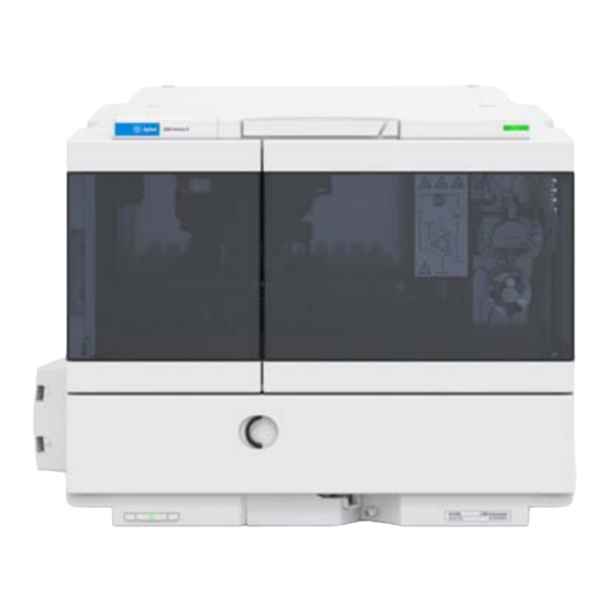
- Page 10 80 °C as well as a sample thermostat for stable temperatures from 4 °C to 40 °C, all within one module. Status indicator Needle assembly Drawer Column shelf Leak drain Power switch Figure 1 Overview of the Vialsampler Agilent InfinityLab LC Series Vialsamplers User Manual...
- Page 11 "bypass" mode. • Increased productivity – with overlapped injections. • Customizable injection program – available for customizing advanced injections as well as for sample preparation steps upfront injection. Agilent InfinityLab LC Series Vialsamplers User Manual...
- Page 12 4 °C to 40 °C, all within one module. Status indicator Needle assembly Drawer Column shelf Leak drain Power switch Figure 2 Overview of the Vialsampler Agilent InfinityLab LC Series Vialsamplers User Manual...
- Page 13 • Increased productivity - with overlapped injections. • Customizable Injection program - available for customizing advanced injections as well as for sample preparation steps upfront injection. Agilent InfinityLab LC Series Vialsamplers User Manual...
- Page 14 80 °C as well as a sample thermostat for stable temperatures from 4 °C to 40 °C, all within one module. Status indicator Needle assembly Drawer Column shelf Leak drain Power switch Figure 3 Overview of the Vialsampler Agilent InfinityLab LC Series Vialsamplers User Manual...
- Page 15 "bypass" mode. • Increased productivity – with overlapped injections. • Customizable injection program – available for customizing advanced injections as well as for sample preparation steps upfront injection. Agilent InfinityLab LC Series Vialsamplers User Manual...
- Page 16 Overview of the Module The Agilent InfinityLab LC Series Vialsampler is designed for use with other modules of the Agilent InfinityLab LC Series, 1200 Series, and 1100 Series LC, as well as with other LC systems with adequate remote-control capabilities. The...
- Page 17 Agilent InfinityLab Sample Thermostat (G7167-60101). It features a vapor-compression refrigeration system and an electric heater, allowing the Vialsampler to reach vial temperatures down to 4 °C and up to 40 °C. Agilent InfinityLab LC Series Vialsamplers User Manual...
- Page 18 If this feature is disabled, the gripper arm positions the sample vial directly below the needle (Step 4) and lowers the needle into the vial. Agilent InfinityLab LC Series Vialsamplers User Manual...
- Page 19 Solvent Wash pump Sampling loop Wash Needle Vial port seat Metering device Figure 4 Mainpass (main path) Position - standard position during runs and when the sampler is idle Agilent InfinityLab LC Series Vialsamplers User Manual...
- Page 20 1, and flows directly to the column through port 6. Solvent Wash pump Sampling loop Wash Needle Vial port seat Metering device Figure 5 Valve in bypass - needle in vial, metering device aspirates sample volume Agilent InfinityLab LC Series Vialsamplers User Manual...
- Page 21 In the next step, the needle is washed (see Figure 6 on page 21). Solvent Wash pump Sampling loop Wash Needle Vial port seat Metering device Figure 6 Outer face of needle getting washed in wash port Agilent InfinityLab LC Series Vialsamplers User Manual...
- Page 22 Figure 7 on page 22). Solvent Wash pump Sampling loop Wash Needle Vial port seat Metering device Figure 7 Valve switches to mainpass (main path) - sample is transferred towards the LC column Agilent InfinityLab LC Series Vialsamplers User Manual...
- Page 23 The upper and lower needle positions are detected by reflection sensors on the needle station board, while the needle-in-vial position is determined by counting the motor steps from the upper needle-sensor position. Agilent InfinityLab LC Series Vialsamplers User Manual...
- Page 24 Operating Principle Hydraulic Box The hydraulic box comprises two main assemblies: metering device, and injection valve. Figure 9 Hydraulic Unit The replacement hydraulic box excludes the injection valve and metering head NOTE assemblies. Agilent InfinityLab LC Series Vialsamplers User Manual...
- Page 25 (port 3 is not used). A lever/slider mechanism transfers the movement of the stepper motor to the injection valve. Two microswitches monitor switching of the valve (bypass and mainpass (main path) end positions). No valve adjustments are required after replacing internal components. Agilent InfinityLab LC Series Vialsamplers User Manual...
- Page 26 These positions are used by the processor to calculate the actual motor position. An additional six reflection sensors for tray recognition are mounted on the flex board at the front of the assembly. Agilent InfinityLab LC Series Vialsamplers User Manual...
- Page 27 Introduction Leak and Waste Handling Leak and Waste Handling The Agilent InfinityLab LC Series has been designed for safe leak and waste handling. It is important that all security concepts are understood and instructions are carefully followed. The solvent cabinet is designed to store a maximum volume of 8 L solvent. The maximum volume for an individual bottle stored in the solvent cabinet should not exceed 2 L.
- Page 28 Introduction Leak and Waste Handling Figure 11 Infinity II Leak Waste Concept (Flex Bench installation) Agilent InfinityLab LC Series Vialsamplers User Manual...
- Page 29 Introduction Leak and Waste Handling Figure 12 Infinity II Single Stack Leak Waste Concept (bench installation) Agilent InfinityLab LC Series Vialsamplers User Manual...
- Page 30 Figure 13 Infinity II Two Stack Leak Waste Concept (bench installation) The waste tube connected to the leak plane outlet on each of the bottom instruments guides the solvent to a suitable waste container. Agilent InfinityLab LC Series Vialsamplers User Manual...
- Page 31 The leak sensor in the sampler is hidden under the ICC Column Heater or Column NOTE Shelf respectively. Waste Guidance The waste drainage must go straight into the waste containers. The waste flow NOTE must not be restricted at bends or joints. Agilent InfinityLab LC Series Vialsamplers User Manual...
- Page 32 1 Agilent recommends using the 6 L waste can with 1 Stay Safe cap GL45 with 4 ports (5043-1221) for optimal and safe waste disposal. If you decide to use your own waste solution, make sure that the tubes don't immerse in the liquid. Agilent InfinityLab LC Series Vialsamplers User Manual...
- Page 33 Performance Specifications (G7129B) Performance Specifications (G7129C) Specifications of the Sample Cooler Specifications of the Sample Thermostat Specifications of the Integrated Column Compartment This chapter provides information on environmental requirements, physical and performance specifications. Agilent InfinityLab LC Series Vialsamplers User Manual...
- Page 34 Make sure the power connector of the instrument can be easily reached and unplugged. Provide sufficient space behind the power socket of the instrument to unplug the cable. Agilent InfinityLab LC Series Vialsamplers User Manual...
- Page 35 Never use a power cord other than the one that Agilent shipped with this instrument. Never use the power cords that Agilent Technologies supplies with this instrument for any other equipment. Never use cables other than the ones supplied by Agilent Technologies ...
- Page 36 Agilent recommends that you install the HPLC instrument in the InfinityLab Flex NOTE Bench rack. This option helps to save bench space as all modules can be placed into one single stack. It also allows to easily relocate the instrument to another laboratory. Agilent InfinityLab LC Series Vialsamplers User Manual...
- Page 37 If your module was shipped in cold weather, leave it in its box and allow it to warm slowly to room temperature to avoid condensation. Agilent InfinityLab LC Series Vialsamplers User Manual...
- Page 38 Auto-ignition temperature ≥200 °C (394 °F). If a sample thermostat is included the upper value for humidity can be reduced. Please check your lab conditions to stay beyond dew point values for non–condensing operation. Agilent InfinityLab LC Series Vialsamplers User Manual...
- Page 39 Sample viscosity 0.2 – 5.0 cP range Sample capacity 132 x 2 mL vial (two trays default) 100 x 2 mL vial (two classic trays optional) 36 x 6 mL vials (two trays optional) Agilent InfinityLab LC Series Vialsamplers User Manual...
- Page 40 LC & CE Drivers Instant Pilot (G4208A) with firm- ware B.02.19 or above Lab Advisor B.02.07 or above Communication Controller Area Network (CAN),Local Area Network (LAN) ERI: ready, start, stop and shut-down signals Agilent InfinityLab LC Series Vialsamplers User Manual...
- Page 41 GLP features Early maintenance feedback (EMF) for continuous tracking of instrument usage with user-settable limits and feed- back messages. Electronic records of maintenance and errors. Housing All materials recyclable. Agilent InfinityLab LC Series Vialsamplers User Manual...
- Page 42 Sample viscosity 0.2 – 5.0 cP range Sample capacity 132 x 2 mL vial (two trays default) 100 x 2 mL vial (two classic trays optional) 36 x 6 mL vials (two trays optional) Agilent InfinityLab LC Series Vialsamplers User Manual...
- Page 43 LC & CE Drivers Instant Pilot (G4208A) with firm- ware B.02.19 or above Lab Advisor B.02.07 or above Communication Controller Area Network (CAN), Local Area Network (LAN), ERI: ready, start, stop and shut-down signals Agilent InfinityLab LC Series Vialsamplers User Manual...
- Page 44 GLP features Early maintenance feedback (EMF) for continuous tracking of instrument usage with user-settable limits and feed- back messages. Electronic records of maintenance and errors. Housing All materials recyclable. Agilent InfinityLab LC Series Vialsamplers User Manual...
- Page 45 Agilent UV detector • Wash solution: H O with 0.1 % TFA (3 s) Injection cycle time 18 s for draw speed 200 µL/min Ejection speed: 200 µL/min Injection volume: 1 µL Agilent InfinityLab LC Series Vialsamplers User Manual...
- Page 46 GLP features Early maintenance feedback (EMF) for continuous tracking of instrument usage with user-settable limits and feed- back messages. Electronic records of maintenance and errors. Housing All materials recyclable. Agilent InfinityLab LC Series Vialsamplers User Manual...
- Page 47 Up to 3000 m (9842 ft) Safety standards: Installation category II, Pollution For indoor use only IEC, EN, CSA, UL degree 2 ISM Classification ISM Group 1 Class B According to CISPR 11 Agilent InfinityLab LC Series Vialsamplers User Manual...
- Page 48 2 °C to 6 °C at a setpoint of 4 °C The Agilent Infinity II Sample Cooler is not available for trade sales anymore and NOTE has been replaced by the Agilent InfinityLab Sample Thermostat. Agilent InfinityLab LC Series Vialsamplers User Manual...
- Page 49 Up to 3000 m (9842 ft) Safety standards: Installation category II, For indoor use only IEC, EN, CSA, UL Pollution degree 2 ISM Classification ISM Group 1 Class B According to CISPR 11 Agilent InfinityLab LC Series Vialsamplers User Manual...
- Page 50 2 °C to 6 °C at a setpoint of 4 °C (<25 °C, <50 % r.H.) Minimum firmware revision for the Sample Thermostat is D.07.22. NOTE Minimum LC driver revision for the Sample Thermostat is A.02.14. Agilent InfinityLab LC Series Vialsamplers User Manual...
- Page 51 According to CISPR 11 If a sample cooler is included the upper value for humidity can be reduced. Please check your lab condi- tions to stay beyond dew point values for non–condensing operation. Agilent InfinityLab LC Series Vialsamplers User Manual...
- Page 52 2 columns up to 30 cm and 4.6 mm ID Temperature stability ±0.10 °C at sensor Temperature accuracy ±0.8 K (±0.5 K with calibration) Warm up time 20 – 40 °C in 5 min at sensor Agilent InfinityLab LC Series Vialsamplers User Manual...
- Page 53 Column Tag Information Table Using Column Identification Tags Install the Optional Sample Cooler/Sample Thermostat Unpacking the Unit Install the Sample Cooler/Sample Thermostat Using the Optional Sample Cooler/Sample Thermostat Dashboard Control Interface Control Temperature Mode Online Signals Agilent InfinityLab LC Series Vialsamplers User Manual...
- Page 54 Prepare a Sampler Without Cooler/Thermostat for Transportation Prepare a Sampler with Cooler/Thermostat for Transportation Install the Transport Protection Foam Agilent Local Control Modules This chapter provides information on how to use the module. Agilent InfinityLab LC Series Vialsamplers User Manual...
- Page 55 Using the Module Magnets Magnets Magnets in doors of pumps, autosamplers, detectors, and fraction collectors. Agilent InfinityLab LC Series Vialsamplers User Manual...
- Page 56 Using the Module Turn on/off Turn on/off This procedure exemplarily shows an arbitrary LC stack configuration. Power switch: On Agilent InfinityLab LC Series Vialsamplers User Manual...
- Page 57 Using the Module Turn on/off Turn instrument On/Off with the control software. Power switch: Off Agilent InfinityLab LC Series Vialsamplers User Manual...
- Page 58 5. Resident mode (blinking) - for example during update of main firmware. 6. Bootloader mode (fast blinking). Try to re-boot the module or try a cold-start. Then try a firmware update. Agilent InfinityLab LC Series Vialsamplers User Manual...
- Page 59 Right-hand Drawer for 66 x 2 mL Vials: P2-A1 to P2-F11 Right-hand Drawer for 18 x 6 mL Vials: P2-A1 to P2-C6 Drawer for 50 x 2 mL Vials Classic Left: Vial 1-50 Agilent InfinityLab LC Series Vialsamplers User Manual...
- Page 60 Numbering of drawer position (right-hand Drawer for 66 x 2 mL Vials) P1-C6 P1-A1 Figure 16 Numbering of drawer position (left-hand Drawer for 18 x 6 mL Vials) P2-C6 P2-A1 Figure 17 Numbering of drawer position (right-hand Drawer for 18 x 6 mL Vials) Agilent InfinityLab LC Series Vialsamplers User Manual...
- Page 61 Using the Module Vial Drawers and Trays Figure 18 Numbering of drawer position (Drawer for 50 x 2 mL Vials Classic) (Waste Disposal) Figure 19 Numbering of tray position (External tray) Agilent InfinityLab LC Series Vialsamplers User Manual...
- Page 62 Do not operate the sampler without drawers installed. NOTE Install all drawers for best cooling performance. NOTE Do not mix standard and classic drawers. NOTE Install classic drawer 1-50 to the left, classic drawer 51-100 to the right side. Agilent InfinityLab LC Series Vialsamplers User Manual...
- Page 63 Using the Module Vial Drawers and Trays Open the doors of the module. Remove the drawer. Pull the drawer out. Lift the front of the drawer. Lift the drawer out. Remove the drawer. Agilent InfinityLab LC Series Vialsamplers User Manual...
- Page 64 Using the Module Vial Drawers and Trays Install the drawer. Close the doors. Insert the back of the drawer. Align the drawer. Push in the drawer. Agilent InfinityLab LC Series Vialsamplers User Manual...
- Page 65 NOTE For accessing the left drawer, it is sufficient to open the left door only. Insert the vial into an appropriate position of the drawer. 4 Push the vial drawer back into place. Agilent InfinityLab LC Series Vialsamplers User Manual...
- Page 66 Using the Module Vial Drawers and Trays Close the doors. Agilent InfinityLab LC Series Vialsamplers User Manual...
- Page 67 Keep foam and plastic cover in a safe place. NOTE For best temperature performance, and if the external tray is not in use, it is best to cover the opening for the external tray with the original parts. Agilent InfinityLab LC Series Vialsamplers User Manual...
- Page 68 Mount the external tray in the mounting holes on screw driver. the left side of the sampler and ensure that it is pushed in all the way. Remove the foam. Install the disposal tube. Push out the plastic cover. Agilent InfinityLab LC Series Vialsamplers User Manual...
- Page 69 Configure the External Tray in the online view of the Chromatographic Data System: right-click on the sam- pler dashboard and select Modify> External Tray. In the dialog, select the External Tray installed check box. Agilent InfinityLab LC Series Vialsamplers User Manual...
- Page 70 Crimp Top Vial, 2 mL, amber glass, write-on spot, 100/Pack (silanized) 5182-0567 Crimp Top Vial, 1 mL, polypropylene, wide opening, 100/Pack 5183-4496 Crimp Top Vial, 1 mL, polypropylene, wide opening, 100/Pack (silanized) 9301-0978 Crimp top vial, 250 µL, polypropylene, wide opening, 1000/Pack Agilent InfinityLab LC Series Vialsamplers User Manual...
- Page 71 Screw Cap Vial, 2 mL, amber glass, write-on spot, 100/Pack 5183-2069 Screw Top Vial, 2 mL, amber glass, write-on spot, 1000/Pack 5183-2072 Screw Top Vial, 2 mL, amber glass, write-on spot, 100/Pack (silanized) Agilent InfinityLab LC Series Vialsamplers User Manual...
- Page 72 Screw Cap, red polypropylene, septum (clear PTFE/red rubber), 100/Pack 5182-0720 Screw Cap, blue polypropylene, septum (clear PTFE/silicone), 100/Pack 5182-0721 Screw Cap, green polypropylene, septum (clear PTFE/silicone), 100/Pack 5182-0722 Screw Cap, red polypropylene, septum (clear PTFE/silicone), 100/Pack Agilent InfinityLab LC Series Vialsamplers User Manual...
- Page 73 Septum, preslit, PTFE/silicone, for 16 mm caps, 100/Pack Crimp Top Vials and Caps Description 9301-1419 Crimp Top Vial, 6 mL, clear glass, flat bottom, 100/Pack 9301-1425 Crimp Cap, silver aluminum, septum (PTFE/silicone), 100/Pack Agilent InfinityLab LC Series Vialsamplers User Manual...
- Page 74 If your module was shipped in cold weather, leave it in its box and allow it to warm slowly to room temperature to avoid condensation. Agilent InfinityLab LC Series Vialsamplers User Manual...
- Page 75 For parts identification please check the illustrated parts breakdown in “Integrated Column Compartment” on page 288. Please report any missing or damaged parts to your local Agilent Technologies sales and service office. Table 11 Delivery checklist for the Integrated Column Compartment (ICC)
- Page 76 WAR N IN G Solvents may run into the module if column shelf or Integrated Column Compartment are not installed. Install either column shelf or Integrated Column Compartment before starting the module. Agilent InfinityLab LC Series Vialsamplers User Manual...
- Page 77 Push in the Integrated Column Compartment. side. Pull out the column shelf. Ensure that the release buttons are clicked back in their original position. Click The column shelf is removed. The Integrated Column Compartment is installed. Agilent InfinityLab LC Series Vialsamplers User Manual...
- Page 78 ICC heat exchanger with a suitable of the ICC heat exchanger (see “Capillary capillary (see “Capillary Connections” on page 278 for Connections” on page 278 for recommendations). recommendations). Agilent InfinityLab LC Series Vialsamplers User Manual...
- Page 79 NOTE Do not overtighten the fitting (maximum torque 2.5 Nm). NOTE The use of capillaries with SL or SX fittings are recom- mended for a better handling. max. max. 2.5 Nm 2.5 Nm Agilent InfinityLab LC Series Vialsamplers User Manual...
- Page 80 Close the lever to establish a pressure tight connec- The fitting should be pressure tight up to 600 bar. tion. If needed, tighten the fitting further with the help of two suitable wrenches. Agilent InfinityLab LC Series Vialsamplers User Manual...
- Page 81 ICC dedicated for this pur- pose. 13 Close the flap door until the latch is locked. 14 Close the doors. Click 15 Turn on the sampler and the pump. Agilent InfinityLab LC Series Vialsamplers User Manual...
- Page 82 Switch off the sampler • Open the doors of the sampler A maximum of two columns can be installed. NOTE Push the latch of the Integrated Column Compartment Open the flap door. to the left. Agilent InfinityLab LC Series Vialsamplers User Manual...
- Page 83 NOTE Do not overtighten the fitting (maximum torque 2.5 Nm). NOTE The use of capillaries with SL or SX fittings are recom- mended for a better handling. max. max. 2.5 Nm 2.5 Nm Agilent InfinityLab LC Series Vialsamplers User Manual...
- Page 84 Close the lever to establish a pressure tight connec- The fitting should be pressure tight up to 600 bar. tion. If needed, tighten the fitting further with the help of two suitable wrenches. Agilent InfinityLab LC Series Vialsamplers User Manual...
- Page 85 13 If applicable, connect the column identification tag to the tag reader (see “Connect a Column Identification Tag to the Tag Reader” on page 94). 14 Configure the connected column in the CDS (see “Column Assignment” on page 102). Agilent InfinityLab LC Series Vialsamplers User Manual...
- Page 86 Push the latch of the Integrated Column Compartment Open the flap door. to the left. Remove the column from the column holder clips. Loosen the Quick Turn Fitting either with your fingers or with the help of two wrenches. Agilent InfinityLab LC Series Vialsamplers User Manual...
- Page 87 Lift up the lever to release the tension on the Quick Con- nect Fitting. Unscrew and remove the Quick Connect Fitting. Remove the column from the ICC. Close the flap door until the latch is locked. Click Agilent InfinityLab LC Series Vialsamplers User Manual...
- Page 88 Install either column shelf or Integrated Column Compartment before starting the module. Remove the capillary connecting the injection valve and Remove the column from the column holder clips. the ICC heat exchanger. Agilent InfinityLab LC Series Vialsamplers User Manual...
- Page 89 Lift up the lever to release the tension on the Quick Con- Unscrew and remove the Quick Connect Fitting. nect Fitting. Remove the column from the ICC. Close the flap door until the latch is locked. Click Agilent InfinityLab LC Series Vialsamplers User Manual...
- Page 90 Push in the column shelf. Pull out the Integrated Column Compartment. Ensure that the release buttons are clicked back in their original position. Click The Integrated Column Comparment is removed. The column shelf is installed. Agilent InfinityLab LC Series Vialsamplers User Manual...
- Page 91 Using the Module Install the Optional Integrated Column Compartment 11 Close the doors. 12 Turn on the sampler and the pump. Agilent InfinityLab LC Series Vialsamplers User Manual...
- Page 92 Connect the cable of the tag reader to the respective Fix the cable to the back of the sampler with the cable socket on the back of the Vialsampler. clips provided with the tag reader. Agilent InfinityLab LC Series Vialsamplers User Manual...
- Page 93 Power on the instrument. Place a column with an identification tag in the ICC and plug the tag into the tag reader (see “Connect a Column Identi- fication Tag to the Tag Reader” on page 94). Agilent InfinityLab LC Series Vialsamplers User Manual...
- Page 94 ICC” on page 82). end of the column and pulling the cord tight through the plastic holder. NOTE Once the lanyard is fixed, the tag can no longer be removed from the column. Agilent InfinityLab LC Series Vialsamplers User Manual...
- Page 95 Click Close the doors. Configure the connected column with identification tag in the CDS (see “Column Assignment” on page 102 and “Using Column Identification Tags” on page 104). Agilent InfinityLab LC Series Vialsamplers User Manual...
- Page 96 (GUI) for the ICC. ICC: Turn On/Off ICC: Heater Status (On/Off) ICC: Actual Temperature ICC: Set Temperature ICC: Column Information ICC: Status Indicator ICC: Early Maintenance Feedback (EMF) Status ICC: Column Identification Tag Recognised Agilent InfinityLab LC Series Vialsamplers User Manual...
- Page 97 Using the Module Using the Optional Integrated Column Compartment Control Interface Right-clicking on the sampler GUI opens the control interface, where control and method parameters can be edited, column assignment modified, and special commands executed. Agilent InfinityLab LC Series Vialsamplers User Manual...
- Page 98 • Turn on thermostat: The ICC turns on automatically upon powering on the sampler. • Automatic Turn On: • Turn on at: The ICC turns on automatically at the specified time and date. Agilent InfinityLab LC Series Vialsamplers User Manual...
- Page 99 (for example, gradient elutions). For Stoptime and Posttime, valid inputs are 0.01 to 99999 minutes in increments NOTE of 0.1 min. Agilent InfinityLab LC Series Vialsamplers User Manual...
- Page 100 • Timetable: This feature enables the user to use programmed changes to control the oven temperature during the curse of the analysis. Agilent InfinityLab LC Series Vialsamplers User Manual...
- Page 101 In the Online Signals tab of the CDS, the actual temperature of the column oven can be configured and plotted together with the other instrument actuals. This enables the user to have a better overview of how the temperature changes over time. Agilent InfinityLab LC Series Vialsamplers User Manual...
- Page 102 This is referred to as hard tagging. By default, the Column Tag Information table is truncated and only columns up to NOTE and including Injections are displayed. Clicking on >> in the top right corner displays the whole table. Agilent InfinityLab LC Series Vialsamplers User Manual...
- Page 103 Using the Optional Integrated Column Compartment Column Tag Information Table The Column Tag Information table is part of the Column Assignment dialog box, which can be prompted by clicking on the corresponding button of the control interface. Agilent InfinityLab LC Series Vialsamplers User Manual...
- Page 104 When the column identification tag is sealed, the static fields will become NOTE write-protected and only the dynamic fields will remain available for updating. The only exceptions from this are the Void Volume and Commentstatic fields. Agilent InfinityLab LC Series Vialsamplers User Manual...
- Page 105 Column catalogs are available only in OpenLab CDS ChemStation Edition C.01.07 NOTE SR2 and above with drivers A.02.14 and above. Click the Catalog button to display a dialog box that allows you to choose how to load the catalog into the table. Agilent InfinityLab LC Series Vialsamplers User Manual...
- Page 106 6 If the column is installed and will be used in the Multicolumn Thermostat, select YES in the Installed column. 7 Click the Plumbing button. The Column Assignment dialog box is displayed. Figure 21 Column Assignment dialog box Agilent InfinityLab LC Series Vialsamplers User Manual...
- Page 107 Figure 22 The list of columns from the ChemStation's Edit Columns table To reduce the list to only those columns that are marked as Installed, mark the Only show installed Columns check box. Agilent InfinityLab LC Series Vialsamplers User Manual...
- Page 108 12 You can edit the information on the column ID tag using the ChemStation Edit Columns table. When you have finished editing the information, repeat steps 7 to 9 to update the information in the tag. Agilent InfinityLab LC Series Vialsamplers User Manual...
- Page 109 The sealed column is shown in the Column Tag Information table with the icon at the beginning of the row. In the Edit Columns table of the ChemStation, it is shown with Sealed in the Tag column. Agilent InfinityLab LC Series Vialsamplers User Manual...
- Page 110 Make the connections to give the shortest distances between the valve ports and NOTE the columns, and use a logical order (left column 1 to port 1-1, left column 2 to port 2-2 and so on). Avoid leaving unused ports between used ones. Agilent InfinityLab LC Series Vialsamplers User Manual...
- Page 111 ); the tooltip shows the information currently stored on the column ID tag. Note that the column ID tag icon changes according to its state as described “The Column Tag Information Table” on page 113. Agilent InfinityLab LC Series Vialsamplers User Manual...
- Page 112 The ChemStation also provides a catalog of column types, which you can load into the Edit Columns table to act as templates for other columns. Agilent InfinityLab LC Series Vialsamplers User Manual...
- Page 113 By default, only the Column Tag Information table columns up to and including the Injection column are displayed. Click the >> button at the top right of the table to show the full table. Agilent InfinityLab LC Series Vialsamplers User Manual...
- Page 114 Whether or not the column was supplied by Static Read Write Agilent Technologies. Serial Number The serial number of the column. Static Read Write Batch Number The batch number of the column. Static Read Write Agilent InfinityLab LC Series Vialsamplers User Manual...
- Page 115 Tag Sealed Whether or not all static fields except Comment Static Read Write and Void Volume are set irrevocably to read-only. Comment A user-generated comment about the column. Static Write Write Agilent InfinityLab LC Series Vialsamplers User Manual...
- Page 116 For parts identification, please check the illustrated parts breakdown in “Sample Thermostat Upgrade” on page 287. Please report any missing or damaged parts to your local Agilent Technologies sales and service office. Table 12 Delivery checklist for the Sample Thermostat...
- Page 117 Flammable refrigerant used WAR N IN G When handling, installing and operating the Sample Thermostat, care should be taken to avoid damage to the refrigerant tubing or any part of the Sample Thermostat. Agilent InfinityLab LC Series Vialsamplers User Manual...
- Page 118 Depending on the ambient conditions in the lab, the amount of condensate can NOTE vary from 200 mL to 2 L per day. Do not fill waste containers for the condensate to the top. Regularly empty the waste container. Agilent InfinityLab LC Series Vialsamplers User Manual...
- Page 119 Ensure that the power switch on the front of the module Disconnect the power cable from the sampler. is OFF (switch stands out). Loosen the four screws on the rear of the module. Remove the sheet metal back cover of the sampler. Agilent InfinityLab LC Series Vialsamplers User Manual...
- Page 120 Sample Cooler/Sample Thermostat cables. Connect the power cable and the data cable to the Sam- ple Cooler/Sample Thermostat. Agilent InfinityLab LC Series Vialsamplers User Manual...
- Page 121 NOTE Ensure a distance of 60 mm from the bottom edge. To ensure adequate drainage for condensate, the module should be operated in a proper horizontal position. Agilent InfinityLab LC Series Vialsamplers User Manual...
- Page 122 Wait at least 30 min before switching on the compres- sor of the cooler/thermostat. This allows the refrigerant and system lubrication to reach equilibrium. 13 Connect the power cable to the power connector at the rear of the module. Agilent InfinityLab LC Series Vialsamplers User Manual...
- Page 123 Sampler: Analytical head configuration Sampler: Injection volume Sampler: Hotel configuration Sampler: Status indicator Sampler: Early Maintenance Feedback (EMF) status Sampler: Multiwash installed Cooler/Thermostat: Status indicator (Off) Cooler/Thermostat: Status indicator (On) Cooler/Thermostat: Set temperature Cooler/Thermostat: Actual temperature Agilent InfinityLab LC Series Vialsamplers User Manual...
- Page 124 Temperature within +/- 2 °C function is selected. Control Interface Right-clicking the sampler GUI will prompt the control interface, where control and method parameters can be edited, configuration modified, and special commands executed. Agilent InfinityLab LC Series Vialsamplers User Manual...
- Page 125 Temperature within +/- 2 °C: The analysis starts only when the actual temperature is within the ± 2 °C range of the setpoint temperature. The Temperature within +/- 2 °C option is only available for the Sample NOTE Thermostat. Agilent InfinityLab LC Series Vialsamplers User Manual...
- Page 126 Using the Module Using the Optional Sample Cooler/Sample Thermostat Agilent InfinityLab LC Series Vialsamplers User Manual...
- Page 127 (for example, from 4 to 40 °C or vice versa). • It might be beneficial to use the Temperature within +/- 2 °C function; otherwise, the next run will start without waiting for the new setpoint being reached. Agilent InfinityLab LC Series Vialsamplers User Manual...
- Page 128 In the Online Signals tab of the CDS, the actual temperature of the sample space can be configured and plotted together with the other instrument actuals. This enables the user to have a better overview of how the temperature changes over time. Agilent InfinityLab LC Series Vialsamplers User Manual...
- Page 129 Finding the Advanced Run Information setting in OpenLab CDS 2.4. Figure 27 Reporting actual and setpoint temperature using theAdvanced Run Information setting. For OpenLab CDS ChemStation, this option is only available in Intelligent NOTE Reporting. Agilent InfinityLab LC Series Vialsamplers User Manual...
- Page 130 Setting the cooler/thermostat from a lower to a higher temperature setpoint, or just simply turning it off, can result in dew formation on the internal surfaces of the sampler. This is normal and should cease after a couple of hours at the most. Agilent InfinityLab LC Series Vialsamplers User Manual...
- Page 131 Make sure that all condensate is removed from the cooler/thermostat. Gently tapping on the sides of the sampler facilitates the condensate removal. NOTE Tilting the module towards its right back corner is not recommended as it can damage the internal parts. Agilent InfinityLab LC Series Vialsamplers User Manual...
- Page 132 2 Move the transport assembly to the park position using Instant Pilot or Lab Advisor, see “Park Arm” on page 186. 3 Turn off the sampler. 4 Install the Transport Protection Foam, see “Install the Transport Protection Foam” on page 135. Agilent InfinityLab LC Series Vialsamplers User Manual...
- Page 133 Moving the sampler with the Sample Cooler/Sample Thermostat installed is NOTE possible for short distances (for example, from one workbench to another). For longer transportation, remove the cooler/thermostat from the sampler and handle the units separately. Agilent InfinityLab LC Series Vialsamplers User Manual...
- Page 134 6 Install the Transport Protection Foam, see “Install the Transport Protection Foam” on page 135. 7 Remove the Sample Cooler/Sample Thermostat from the sampler if needed, “Replace the Sample Cooler/Sample Thermostat” on page 270. Agilent InfinityLab LC Series Vialsamplers User Manual...
- Page 135 Move the gripper arm into the park position (see “Park Arm” on page 186) and turn off the sampler. Place the Transport Protection Foam into the sampler. Push the Transport Foam in until the endpoint. Agilent InfinityLab LC Series Vialsamplers User Manual...
- Page 136 Using the Module Transporting the Sampler Ensure that the foam is snapped behind the upper part Close the doors. of the metal frame. Agilent InfinityLab LC Series Vialsamplers User Manual...
- Page 137 • a clear overview of the system status • control functionalities • access to method parameters and sequences • a logbook showing events from the modules • diagnose tests Agilent InfinityLab LC Series Vialsamplers User Manual...
- Page 138 Factory installed software – flat dialog structure, user configurable interface, enhanced sequence engine, for example with wait for baseline stabilization, diagnosis with passed/failed. • GLP – System logbook and module logbooks record errors, unusual events, and maintenance activities for GLP traceability. Agilent InfinityLab LC Series Vialsamplers User Manual...
- Page 139 Capillary Color Coding Guide Installing Capillaries Flow Connections to the Vialsampler Setting up the Vialsampler Control Settings Method Parameter Settings Injector Programm Module Configuration View This chapter explains the operational parameters of the module. Agilent InfinityLab LC Series Vialsamplers User Manual...
- Page 140 For details, see the usage guideline for the solvent cabinet. A printed copy of the NOTE guideline has been shipped with the solvent cabinet, electronic copies are available in the Agilent Information Center or via the Internet. For details on correct installation, see separate installation documentation. Agilent InfinityLab LC Series Vialsamplers User Manual...
- Page 141 To clean the system when Bidistilled water Best solvent to re-dissolve buf- using buffers fer crystals After a solvent change Bidistilled water Best solvent to re-dissolve buf- fer crystals Agilent InfinityLab LC Series Vialsamplers User Manual...
- Page 142 (especially for basic compounds) • water/base (especially for acidic compounds) • water/acetonitrile For different wash solvents as mentioned above, verify that the wash solvent is NOTE suitable for the silicone wash tubing. Agilent InfinityLab LC Series Vialsamplers User Manual...
- Page 143 • good • very good • medium • unsatisfactory • very good • strong • not recommended • good Hydrocarbons • aliphatic •not recommended • aromatizised •not recommended • halogenated •not recommended Agilent InfinityLab LC Series Vialsamplers User Manual...
- Page 144 PEEK capillaries keeps the flow path free of steel and ensures pressure stability to at least 600 bar. If in doubt, consult the available literature about the chemical compatibility of PEEK. Agilent InfinityLab LC Series Vialsamplers User Manual...
- Page 145 High concentrations of inorganic acids like nitric acid, sulfuric acid and organic solvents especially at higher temperatures (replace, if your chromatography method allows, by phosphoric acid or phosphate buffer which are less corrosive against stainless steel). Agilent InfinityLab LC Series Vialsamplers User Manual...
- Page 146 (about 3 %). Slight corrosion is possible with ammonia > 10 %. Diamond-Like Carbon (DLC) Diamond-Like Carbon is inert to almost all common acids, bases and solvents. There are no documented incompatibilities for HPLC applications. Agilent InfinityLab LC Series Vialsamplers User Manual...
- Page 147 For optimizing the life of the pressure sensor, do not leave HFIP in the chamber when the unit is off. The tubing of the leak sensor is made of PVDF (polyvinylidene fluoride), which is incompatible with the solvent DMF (dimethyl formamide). Agilent InfinityLab LC Series Vialsamplers User Manual...
- Page 148 Sapphire, Ruby and Al -based ceramics Sapphire, ruby and ceramics based on aluminum oxide Al are inert to almost all common acids, bases and solvents. There are no documented incompatibilities for HPLC applications. Agilent InfinityLab LC Series Vialsamplers User Manual...
- Page 149 Preparing the Module Capillary Color Coding Guide Capillary Color Coding Guide Figure 28 Syntax for capillary description Agilent InfinityLab LC Series Vialsamplers User Manual...
- Page 150 Quantity depends on configuration of the module (number of connections to the multisampler). The capillaries mentioned above are examples only. Select a nut that is long enough for the fitting you'll be Slide the nut over the end of the tubing or capillary. using. Agilent InfinityLab LC Series Vialsamplers User Manual...
- Page 151 If changing from a column or an injection valve to another, the fitting may leak or decrease the quality of the separation by contributing to band broadening. Agilent InfinityLab LC Series Vialsamplers User Manual...
- Page 152 4 Route the drainage of the washport outlet to the waste container. 5 Prime the wash tubing. 6 Install the capillary from the pump outlet into the port 1 of the injection valve. Agilent InfinityLab LC Series Vialsamplers User Manual...
- Page 153 7 Install the capillary from port 6 of the injection valve to the ICC or MCT The correct plumbing is shown in the figure below and is attached to the module. Waste Pump Column 8 Prime and purge the complete sampler. Agilent InfinityLab LC Series Vialsamplers User Manual...
- Page 154 Figure 29 ChemStation Method and Run Control After successful load of the OpenLab ChemStation, you should see the module as an active item in the graphical user interface (GUI). Agilent InfinityLab LC Series Vialsamplers User Manual...
- Page 155 Check which sample drawers are installed Get the status of the EMF (Early Maintenance Feature) Cooling Temperatur (if Sample Cooler/Sample Thermo- stat is installed) Current instrument information on: • Injection volume • Sample location Agilent InfinityLab LC Series Vialsamplers User Manual...
- Page 156 The needle wash spec- ified in this dialog box is carried out immediately. • Modify • Flow Path: for the sample loops, needle seat, exten- sion loops and metering devices • External Tray • Temperature Mode Agilent InfinityLab LC Series Vialsamplers User Manual...
- Page 157 For additional help and support, highlight the desired area and press the F1 key. A NOTE help screen will open with additional information and documentation about the topic. The Vialsampler configuration is done in the online module dashboard context NOTE menu, not in the instrument configuration view. Agilent InfinityLab LC Series Vialsamplers User Manual...
- Page 158 Preparing the Module Setting up the Vialsampler Control Settings The control settings are available via right click on the active area of the grafical user interface, see Table 15 on page 155. Agilent InfinityLab LC Series Vialsamplers User Manual...
- Page 159 Temperature is within ± 2 °C range of the setpoint temperature. NOTE The Enable Analysis section is disabled when Not con- trolled is selected in the Temperature section. Agilent InfinityLab LC Series Vialsamplers User Manual...
- Page 160 Method Parameter Settings The method parameter settings are available via right click on the active area of the grafical user interface. Figure 31 Method parameter settings Agilent InfinityLab LC Series Vialsamplers User Manual...
- Page 161 Posttime to delay the start of the next analysis. A Post- time period can be used to allow the column to equilibrate after changes in solvent composition (for example after gradient elution). Limits: 0.01 through 99999 min or Off. Agilent InfinityLab LC Series Vialsamplers User Manual...
- Page 162 (in mm) away from its standard position. The Offset function is useful when analyzing very small sample volumes, or when only a specific part of the sample is required, for exam- ple, the top layer. Agilent InfinityLab LC Series Vialsamplers User Manual...
- Page 163 For additional help and support, highlight the desired area in the user interface NOTE and press the F1 key. A help screen will open with additional information and documentation about the topic. Agilent InfinityLab LC Series Vialsamplers User Manual...
- Page 164 The following functions are available : • Draw • Eject • • Inject • Move • Wait • Valve • Needle • Wash • Remote • Wait For • Repeat . End Repeat • Comment Agilent InfinityLab LC Series Vialsamplers User Manual...
- Page 165 For additional help and support. Highlight the desired area and press the F1 key. NOTE A help screen will open with additional information and documentation about the topic. The vialsampler configuration is done in the module dashboard context menu, NOTE not in the instrument configuration. Agilent InfinityLab LC Series Vialsamplers User Manual...
- Page 166 Fast Injection Cycle and Low Delay Volume Overlapped Injection Mode General Recommendations for Fast Injection Cycle Times Precise Injection Volume Draw and Eject Speed Choice of Rotor Seal This chapter provides information on how to optimize the module. Agilent InfinityLab LC Series Vialsamplers User Manual...
- Page 167 10 to 20 s for more complete washing. It is recommended that washing the outside of the needle in the flush port should be standard procedure to avoid contaminating the needle seat. Agilent InfinityLab LC Series Vialsamplers User Manual...
- Page 168 3 INJECT Line 1 moves the needle to vial P2-A1 or the flushport. Line 2 draws 5 µL from the current sample vial P1-A1. Line 3 injects the sample (valve switches to main pass). Agilent InfinityLab LC Series Vialsamplers User Manual...
- Page 169 Wait (equilibration time - see text above) Valve bypass Wait 0.2 min Valve mainpass (main path) Valve bypass Valve mainpass (main path) Overlapped injection together with additional injection valve switching is not NOTE possible. Agilent InfinityLab LC Series Vialsamplers User Manual...
- Page 170 Clean the needle seat with a tissue and remove all liquid. Again be careful not to risk an injury by the uncovered needle. • Reinstall the safety cover of the sampler. • In Lab Advisor, go to Maintenance> Change Needle and finish the procedure. Agilent InfinityLab LC Series Vialsamplers User Manual...
- Page 171 To overcome this, it is recommended to add an extra “blank” injection as last injection to the sequence. Agilent InfinityLab LC Series Vialsamplers User Manual...
- Page 172 Increase of draw and eject speed for large injection volumes • Add at last run a blank, if overlapped injection is used To reduce the injection time, the detector balance has to be set to OFF. Agilent InfinityLab LC Series Vialsamplers User Manual...
- Page 173 If the pump has no degasser, it is recommended to use an Agilent 1260 Infinity degasser. Also, using the automated needle wash (see “Optimization for Lowest Carryover” on page 167) between injections reduces carryover to a minimum, further improving the injection volume precision. Agilent InfinityLab LC Series Vialsamplers User Manual...
- Page 174 An EJECT statement in an injector program also uses the eject speed setting which is configured for the autosampler. A faster eject speed shortens the time required to run the injector program. When using viscous samples, a high eject speed should be avoided. Agilent InfinityLab LC Series Vialsamplers User Manual...
- Page 175 It is suitable for application using mobile phases within a pH between 1 and 14. Strong oxidizing acids such as concentrated nitric and sulfuric acids are not NOTE compatible with PEEK. Agilent InfinityLab LC Series Vialsamplers User Manual...
- Page 176 Park Arm Diagnostic Tests Sample Cooler Function Test Heater Test Agilent Lab Advisor Software This chapter gives an overview of the maintenance, troubleshooting, and diagnostic features available for the Agilent InfinityLab Series Vialsampler. Agilent InfinityLab LC Series Vialsamplers User Manual...
- Page 177 The module status indicator light is situated in the upper right corner of the module and provides information on the actual operating state of the system (see “Status Indicators” on page 58 for more information). Agilent InfinityLab LC Series Vialsamplers User Manual...
- Page 178 Park Arm Tool Injector Steps Tool Gripper Verifica- Tool tion Automatic Refer- Tool encing ALS Torque Verifi- Tool cation Sample Cooler Test Function Test Heater Test Test only available for customer engineers Agilent InfinityLab LC Series Vialsamplers User Manual...
- Page 179 Risk of injury Do not touch the tip of the needle. Keep your fingers off the moving needle. Wear safety goggles when handling an uncovered needle. Agilent InfinityLab LC Series Vialsamplers User Manual...
- Page 180 241) and click Next to continue. 12 Ensure that the needle tip is concentric with the seat. Use the Move Up and Move Down buttons to move the needle closer to or further away from the seat. Agilent InfinityLab LC Series Vialsamplers User Manual...
- Page 181 5 In the following pop-up window, specify whether or not the EMF counter of the metering seal should be reset, then click OK. 6 Select Back in the bottom right corner to exit the Maintenance Positions function. Agilent InfinityLab LC Series Vialsamplers User Manual...
- Page 182 “Exchange the Gripper Arm” on page 258). 4 Click Next to move the gripper arm back to the home position. 5 Select Back in the bottom right corner to exit the Maintenance Positions function. Agilent InfinityLab LC Series Vialsamplers User Manual...
- Page 183 In the case of an error, use the Reset button to bring the sampler back to its NOTE normal operating state. 5 Select Back in the bottom right corner to exit the Gripper Verification function. Agilent InfinityLab LC Series Vialsamplers User Manual...
- Page 184 4 Select Back in the bottom right corner to exit the Gripper Verification function. The vial is returned, the metering plunger moves into the home position, and the injection valve switches into the mainpass position. Agilent InfinityLab LC Series Vialsamplers User Manual...
- Page 185 Valve Mainpass The injection valve switches into the mainpass Needle into Seat position. Reset The sampler gets reset and will reinitialize Prerequisite steps are executed automatically if not already done. Agilent InfinityLab LC Series Vialsamplers User Manual...
- Page 186 Ensure that all vials are removed from the vial drawers. Ensure that the transport assembly is in the park position. Ensure that the Transport Protection Foam (G7129-40050) is correctly installed. Agilent InfinityLab LC Series Vialsamplers User Manual...
- Page 187 (5 – 9 Ohm). For testing the heater resistance of the Sample Thermostat, Lab Advisor version NOTE B.02.11 or higher is needed. Agilent InfinityLab LC Series Vialsamplers User Manual...
- Page 188 To circumvent any negative effect on the test result, the Sample Cooler/Sample NOTE Thermostat is turned off for the duration of the test if present. Agilent InfinityLab LC Series Vialsamplers User Manual...
- Page 189 The optional Agilent Maintenance Wizard Add-on provides an easy-to-use, step-by-step multimedia guide for performing preventive maintenance on Agilent 1200 Infinity and Agilent InfinityLab LC Series instrument. The tests and diagnostic features that are provided by the Agilent Lab Advisor software may differ from the descriptions in this manual. For details, refer to the Agilent Lab Advisor software help files.
- Page 190 Wash procedure failed Start of maintenance procedure failed errors Injection valve position not found Cannot move metering, the metering type definition is incorrect Initialization failed errors Unexpected block during axis movement Timeout during axis movement Agilent InfinityLab LC Series Vialsamplers User Manual...
- Page 191 Trend analysis for the heater temperature sensors failed Maximum heater temperature exceeded Column heater not connected This chapter describes the meaning of error messages, and provides information on probable causes and suggested actions how to recover from error conditions. Agilent InfinityLab LC Series Vialsamplers User Manual...
- Page 192 In all cases, error propagation is done via the CAN bus or via an APG/ERI remote cable (see documentation for the APG/ERI interface). Agilent InfinityLab LC Series Vialsamplers User Manual...
- Page 193 Check the logbook for the occurrence and source A not-ready condition was present during a of a not-ready condition. Restart the analysis sequence or multiple-injection run for a where required. period longer than the timeout threshold. Agilent InfinityLab LC Series Vialsamplers User Manual...
- Page 194 Check the vacuum degasser for an error condi- The degasser failed to generate sufficient tion. Refer to the Service Manual for the degasser vacuum for solvent degassing. or the pump that has the degasser built-in. Agilent InfinityLab LC Series Vialsamplers User Manual...
- Page 195 Ensure all CAN cables are installed correctly. Exchange the CAN cable. Defective CAN cable. Switch off the system. Restart the system, and Defective mainboard in another module. determine which module or modules are not rec- ognized by the system. Agilent InfinityLab LC Series Vialsamplers User Manual...
- Page 196 Make sure the leak sensor is thoroughly dry before restarting the autosampler. Exchange the peristaltic pump. Leaking peristaltic pump The leak sensor in the sampler is hidden under the ICC Column Heater or Column NOTE Shelf respectively. Agilent InfinityLab LC Series Vialsamplers User Manual...
- Page 197 Please contact your Agilent service representa- Defective leak sensor. tive. Please contact your Agilent service representa- Leak sensor incorrectly routed, being tive. pinched by a metal component. Please contact your Agilent service representa- Power switch assembly defective tive. Agilent InfinityLab LC Series Vialsamplers User Manual...
- Page 198 Leak sensor incorrectly routed, being tive. pinched by a metal component. Please contact your Agilent service representa- Power switch assembly defective tive. Please contact your Agilent service representa- Cable or contact problem. tive. Agilent InfinityLab LC Series Vialsamplers User Manual...
- Page 199 Probable cause Suggested actions Please contact your Agilent service representa- Defective power switch assembly tive. Please contact your Agilent service representa- Loose connection between the power switch tive. board and the mainboard Agilent InfinityLab LC Series Vialsamplers User Manual...
- Page 200 Fan cable disconnected. tive. Please contact your Agilent service representa- Defective fan. tive. Replace the Sample Cooler/Sample Thermostat. Defective Sample Cooler/Sample Thermo- stat fan Please contact your Agilent service representa- Defective mainboard. tive. Agilent InfinityLab LC Series Vialsamplers User Manual...
- Page 201 Error ID: 34217 → Transport command failed • Error ID: 34220 → Valve command failed Probable cause Suggested actions Identify the source error message and follow the Command failed instructions provided for that. Agilent InfinityLab LC Series Vialsamplers User Manual...
- Page 202 Please contact your Agilent service representa- Potential hardware error tive. Look for potential sources of physical blockage Physical blockage in the path of the gripper arm and eliminate them. Restart the sampler and observe if the problem persists. Agilent InfinityLab LC Series Vialsamplers User Manual...
- Page 203 Verify the correct functioning of the needle arm by using the Injector Steps Lab Advisor tool. • Restart the sampler and observe if the prob- lem persists. Please contact your Agilent service representa- Potential hardware error tive. Agilent InfinityLab LC Series Vialsamplers User Manual...
- Page 204 Gripper Verification and Injector Steps tools. If the gripper arm appears to be out of alignment, contact Agilent for more informa- tion. Please contact your Agilent service representa- Potential hardware error tive. Agilent InfinityLab LC Series Vialsamplers User Manual...
- Page 205 Gripper Verification and Injector Steps tools. If the gripper arm appears to be out of alignment, contact Agilent for more informa- tion. Please contact your Agilent service representa- Potential hardware error tive. Agilent InfinityLab LC Series Vialsamplers User Manual...
- Page 206 34221,1 corresponds to the Z-axis stepper motor. • 34221,2 corresponds to the theta stepper motor. • 34221,3 corresponds to the gripper stepper motor. Probable cause Suggested actions Please contact your Agilent service representa- Potential hardware error tive. Agilent InfinityLab LC Series Vialsamplers User Manual...
- Page 207 Gripper Verification and Injector Steps tools. If the gripper arm appears to be out of alignment, contact Agilent for more informa- tion. Please contact your Agilent service representa- Potential hardware error tive. Agilent InfinityLab LC Series Vialsamplers User Manual...
- Page 208 To identify these source error events, look for entries with the same timestamp as for the Wash procedure failed error message. Probable cause Suggested actions Identify the source error message and follow the Wash procedure failed instructions provided for that. Agilent InfinityLab LC Series Vialsamplers User Manual...
- Page 209 Broken rotor seal and if necessary, replace it. Check the stator for signs of visible damage and Broken stator if necessary, replace it. Please contact your Agilent service representa- Potential hardware error tive. Agilent InfinityLab LC Series Vialsamplers User Manual...
- Page 210 Error ID: 34325 → Transport initialization failed • Error ID: 34326 → Sampler initialization failed Probable cause Suggested actions Identify the source error message and follow the Initialization failed instructions provided for that. Agilent InfinityLab LC Series Vialsamplers User Manual...
- Page 211 Gripper Verification and Injector Steps tools. If the gripper arm appears to be out of alignment, contact Agilent for more informa- tion. Please contact your Agilent service representa- Potential hardware error tive. Agilent InfinityLab LC Series Vialsamplers User Manual...
- Page 212 Please contact your Agilent service representa- Potential hardware error tive. Verify that the alignment parameters are in the Misaligned gripper arm correct range and perform the Automatic Refer- encing if needed. Agilent InfinityLab LC Series Vialsamplers User Manual...
- Page 213 • Make sure that no kinks or mechanical blocks are present in the drainage system. • Avoid the formation of the siphoning effect. • Make sure that the hosting sampler is level. Agilent InfinityLab LC Series Vialsamplers User Manual...
- Page 214 Units with the serial number DEBAT02000 or below are equipped with an analog temperature sensor that is not compatible with the Vialsam- pler. Please contact your Agilent service representa- Potential hardware error tive. Agilent InfinityLab LC Series Vialsamplers User Manual...
- Page 215 Error ID: 30275 The system is in the error state because the compressor control board has encountered an unexpected error. Probable cause Suggested actions Please contact your Agilent service representa- Potential hardware error tive. Agilent InfinityLab LC Series Vialsamplers User Manual...
- Page 216 Potential hardware error tive. Heater defect Error ID: 30739 The heating function of the thermostat is not working properly. Probable cause Suggested actions Please contact your Agilent service representa- Potential hardware error tive. Agilent InfinityLab LC Series Vialsamplers User Manual...
- Page 217 The system is in the error state because the control board of the compressor has encountered an unexpected error. Probable cause Suggested actions Please contact your Agilent service representa- Potential hardware error tive. Agilent InfinityLab LC Series Vialsamplers User Manual...
- Page 218 Thermostat fan defect Error ID: 30771 One of the cooling fans of the cooler/thermostat is not working properly. Probable cause Suggested actions Please contact your Agilent service representa- Potential hardware error tive. Agilent InfinityLab LC Series Vialsamplers User Manual...
- Page 219 Power off the system and verify that the ICC Connection problems is correctly mounted in the sampler. • Power on the system and check if the prob- lem persists. Please contact your Agilent service representa- Potential hardware error tive. Agilent InfinityLab LC Series Vialsamplers User Manual...
- Page 220 Power off the system and verify that the ICC Connection problems is correctly mounted in the sampler. • Power on the system and check if the prob- lem persists. Please contact your Agilent service representa- Potential hardware error tive. Agilent InfinityLab LC Series Vialsamplers User Manual...
- Page 221 Power off the system and verify that the ICC Connection problems is correctly mounted in the sampler. • Power on the system and check if the prob- lem persists. Please contact your Agilent service representa- Potential hardware error tive. Agilent InfinityLab LC Series Vialsamplers User Manual...
- Page 222 Replace the Analytical Heads Exchange the Gripper Arm Replace the Peristaltic Pump Cartridge Exchange the Wash Port Assembly Replace the Module Firmware Replace the Sample Cooler/Sample Thermostat This chapter describes the maintenance of the module. Agilent InfinityLab LC Series Vialsamplers User Manual...
- Page 223 The module is designed for easy maintenance. Maintenance can be done from the front with module in place in the system stack. Status indicator Needle assembly Drawer Column shelf Leak drain Power switch Figure 33 Overview of the Vialsampler Agilent InfinityLab LC Series Vialsamplers User Manual...
- Page 224 Only certified persons are authorized to carry out repairs inside the module. Sharp metal edges WAR N IN G Sharp-edged parts of the equipment may cause injuries. To prevent personal injury, be careful when getting in contact with sharp metal areas. Agilent InfinityLab LC Series Vialsamplers User Manual...
- Page 225 Avoid back strain or injury by following all precautions for lifting heavy objects. Ensure that the load is as close to your body as possible. Ensure that you can cope with the weight of your load. Agilent InfinityLab LC Series Vialsamplers User Manual...
- Page 226 Overview of maintenance Procedure Typical interval (minimum) Change needle/needle seat 30000 needle into seat movements Change peristaltic pump cartridge 3000 h on time Change rotor seal 30000 injections Change metering seal 30000 injections Agilent InfinityLab LC Series Vialsamplers User Manual...
- Page 227 Drain all solvent lines before opening any connections in the flow path. A solution of 70 % isopropanol and 30 % water might be used if the surface of the NOTE module needs to be disinfected. Agilent InfinityLab LC Series Vialsamplers User Manual...
- Page 228 Press the release buttons and pull the front door out. For the Installation of the front door, insert the hinges into their guides and push the door in until the release buttons click into their final position. Agilent InfinityLab LC Series Vialsamplers User Manual...
- Page 229 When working with these substances observe appropriate safety procedures (for example by wearing goggles, safety gloves and protective clothing) as described in the material handling and safety data sheet supplied by the vendor, and follow good laboratory practice. Agilent InfinityLab LC Series Vialsamplers User Manual...
- Page 230 Diagnostics> Maintenance Positions> Change Needle, Loop and Seat, click Start and wait until the needle assembly is in maintenance position. In the Local Controller start the maintenance mode and select Change Needle, Loop and Seat function. Agilent InfinityLab LC Series Vialsamplers User Manual...
- Page 231 Do not change the needle seat at this point. Do not touch the tip of the needle. Move the wash port into the service position by slightly lifting it up and then flapping to the left. Agilent InfinityLab LC Series Vialsamplers User Manual...
- Page 232 Disconnect the sample loop from the needle, and, if Loosen the fixing screw. needed, also from the metering device. Lift out the needle. 10 Mount and align the needle on its fixture, then tighten the screw firmly. Agilent InfinityLab LC Series Vialsamplers User Manual...
- Page 233 13 In Lab Advisor use Next to lift the needle slowly into the 14 Move the wash port back into its normal position by up position. turning it to the right. In the Local Controller, move the needle up to the upper- most position. Agilent InfinityLab LC Series Vialsamplers User Manual...
- Page 234 In the Local Controller, select Continue to move the nee- (1.) dle into the needle seat and then Exit to finish the main- (2.) tenance procedure. 17 Close the doors. 18 Perform a System Pressure Test. Agilent InfinityLab LC Series Vialsamplers User Manual...
- Page 235 Chromatographic Data System. See Table 15 on page 155. It is recommended to always exchange the needle assembly and the needle seat NOTE at the same time to prevent premature leakage. Agilent InfinityLab LC Series Vialsamplers User Manual...
- Page 236 Change Needle, Loop and Seat function. Loosen the safety cover screw. WAR N IN G Sharp needle Uncovered needles may cause injuries Do not touch the tip of the needle. Remove the safety cover. Agilent InfinityLab LC Series Vialsamplers User Manual...
- Page 237 Move the wash port into the service position by slightly lifting it up and then flapping to the left. Disconnect the sample loop from the needle, and, if Loosen the fixing screw. needed, also from the metering device. Agilent InfinityLab LC Series Vialsamplers User Manual...
- Page 238 11 Insert the new needle seat and press it firmly into posi- 12 Mount and align the needle on its fixture, then tighten tion. Then, connect the seat capillary fitting to port 5 of the screw firmly. the injection valve. Agilent InfinityLab LC Series Vialsamplers User Manual...
- Page 239 15 Move the wash port back into its normal position by 16 Install the safety cover (1.) and fix the screw (2.). turning it to the right. (1.) (2.) Agilent InfinityLab LC Series Vialsamplers User Manual...
- Page 240 Back to finish the maintenance procedure. In the Local Controller, select Continue to move the nee- dle into the needle seat and then Exit to finish the main- tenance procedure. 19 Perform a System Pressure Test. Agilent InfinityLab LC Series Vialsamplers User Manual...
- Page 241 Wear safety goggles and safety gloves when removing the needle assembly. When the instrument setup has changed, configure the new setup in the online NOTE view of the Chromatographic Data System. See Table 15 on page 155. Agilent InfinityLab LC Series Vialsamplers User Manual...
- Page 242 Change Needle, Loop and Seat function. Loosen the safety cover screw. WAR N IN G Sharp needle Uncovered needles may cause injuries Do not touch the tip of the needle. Remove the safety cover. Agilent InfinityLab LC Series Vialsamplers User Manual...
- Page 243 NOTE Incorrect positioning and installation of the needle/loop connection can result in damaging and breaking the sample loop. Agilent InfinityLab LC Series Vialsamplers User Manual...
- Page 244 In the Local Controller, select Continue to move the nee- (1.) dle into the needle seat and then Exit to finish the main- (2.) tenance procedure. 13 Close the doors. 14 Perform a System Pressure Test. Agilent InfinityLab LC Series Vialsamplers User Manual...
- Page 245 The stator face is held in place by the stator head. When you remove the stator head, the stator face can fall out of the valve. Carefully handle the valve to prevent damage to the stator face. Carefully handle the stator face during sonication. Agilent InfinityLab LC Series Vialsamplers User Manual...
- Page 246 Remove all capillaries from the injection valve with a 1/4 inch wrench. Loosen each fixing bolt two turns at a time. Remove the Remove the stator head and stator ring. bolts from the head. Agilent InfinityLab LC Series Vialsamplers User Manual...
- Page 247 NOTE Make sure that the rotor sealing surface with its engraved flow passages is facing out. The pattern is asymmetrical to prevent improper placement. Agilent InfinityLab LC Series Vialsamplers User Manual...
- Page 248 Do not over-tighten the screws. The screws hold the assem- bly together and do not affect the sealing force. The sealing force is automatically set as the screws close the stator head against the valve body. Agilent InfinityLab LC Series Vialsamplers User Manual...
- Page 249 10 Slide the waste tube into the waste holder in the leak tray. The correct plumbing is shown below and on the safety cover of the module. Waste Pump Column 11 Close the doors. 12 Perform a System Pressure Test. Agilent InfinityLab LC Series Vialsamplers User Manual...
- Page 250 Close the shutoff valves at the pump if available. When the instrument setup has changed, configure the new setup in the online NOTE view of the Chromatographic Data System. See Table 15 on page 155. Agilent InfinityLab LC Series Vialsamplers User Manual...
- Page 251 Disconnect the two capillaries from the metering Remove the two fixing bolts. device. Remove the metering head assembly from the sampler. Remove the two fixing bolts from the base of the meter- ing head assembly. Agilent InfinityLab LC Series Vialsamplers User Manual...
- Page 252 Clean the chamber with lint-free cloth and an appropri- 10 Use the plastic side of the insert tool to install the new ate solvent. Ensure all particulate matter is removed. seal. Press the seal firmly into position. Agilent InfinityLab LC Series Vialsamplers User Manual...
- Page 253 Back to finish the mainte- nance procedure. In the Local Controller, select Continue to move the pis- ton back into its normal position and then Exit to finish the maintenance procedure. Agilent InfinityLab LC Series Vialsamplers User Manual...
- Page 254 Maintenance Exchange the Metering Seal and Piston 17 Close the doors. 18 Perform a System Pressure Test. Agilent InfinityLab LC Series Vialsamplers User Manual...
- Page 255 Diagnostics> Maintenance Positions> Change Metering Seal and Piston, click Start and wait until the metering plunger is in maintenance position. In the Local Controller start the maintenance mode and select Change Metering Device function. Agilent InfinityLab LC Series Vialsamplers User Manual...
- Page 256 Back to finish the mainte- nance procedure. In the Local Controller, select Continue to move the pis- ton back into its normal position and then Exit to finish the maintenance procedure. Select Back to finish the procedure. Agilent InfinityLab LC Series Vialsamplers User Manual...
- Page 257 10 Close the doors. Next Steps: 11 Perform a System Pressure Test. 12 If needed, install a sample loop matching the volume of the new analytical head (see “Exchange the Sample Loop Assembly” on page 241). Agilent InfinityLab LC Series Vialsamplers User Manual...
- Page 258 Diagnostics> Maintenance Positions> Change Gripper and wait until the gripper is in maintenance position (see also “Maintenance Positions” on page 179). In the Local Controller start the maintenance mode and select Change Gripper function. Agilent InfinityLab LC Series Vialsamplers User Manual...
- Page 259 You should feel that the lock mechanism releases the NOTE gripper arm. With firmware version D.07.28 or older, it is recommended to turn off the sampler to complete the rest of the proce- dure. Agilent InfinityLab LC Series Vialsamplers User Manual...
- Page 260 With firmware version D.07.28 or older, turn on the sampler and wait until it initializes. 11 Complete the remaining steps prompted in the user interface of the Local Controller or the Agilent Lab Advisor soft- ware. Agilent InfinityLab LC Series Vialsamplers User Manual...
- Page 261 The peristaltic pump cartridge must be replaced as a single entity. The Pharmed NOTE tubing is not replaceable separately. Open the doors of the module. Press the two clips on the front of the peristaltic pump cartridge. Agilent InfinityLab LC Series Vialsamplers User Manual...
- Page 262 (use sand paper to get a good grip on the tubing). Connect the wash solvent line with the plastic fitting to Close the doors. the right side of the cartridge tubing. Agilent InfinityLab LC Series Vialsamplers User Manual...
- Page 263 Diagnostics> Maintenance Positions> Change Needle, Loop and Seat, click Start and wait until the needle assembly is in maintenance position. In the Local Controller start the maintenance mode and select Change Needle, Loop and Seat function. Agilent InfinityLab LC Series Vialsamplers User Manual...
- Page 264 Do not change the needle seat at this point. Remove the safety cover. Do not touch the tip of the needle. Move the wash port into the service position by slightly lifting it up and then flapping to the left. Agilent InfinityLab LC Series Vialsamplers User Manual...
- Page 265 Be careful not to squeeze the wash tubing. NOTE Move the needle holder arm up by a couple of mm if you are facing difficulties with moving the wash port to the right. Agilent InfinityLab LC Series Vialsamplers User Manual...
- Page 266 Check if the tension on the spring is high enough to move the wash port back into position in time. When everything seems to be in order, move the wash port into the service position (see step Agilent InfinityLab LC Series Vialsamplers User Manual...
- Page 267 19 In Lab Advisor use Next to lift the needle slowly into the 20 Move the wash port back into its normal position by up position. turning it to the right. In the Local Controller, move the needle up to the upper- most position. Agilent InfinityLab LC Series Vialsamplers User Manual...
- Page 268 23 Select Back to finish the procedure. Next Steps: 24 Close the doors. 25 Purge the wash port. Check if solvent is delivered from the peristaltic pump. 26 Perform a System Pressure Test. Agilent InfinityLab LC Series Vialsamplers User Manual...
- Page 269 1 Download the required module firmware, the latest FW Update Tool and the documentation from the Agilent web. http://www.agilent.com/en-us/firmwareDownload?whid=69761 2 For loading the firmware into the module follow the instructions in the documentation. Module Specific Information There is no specific information for this module. Agilent InfinityLab LC Series Vialsamplers User Manual...
- Page 270 Flammable refrigerant used WAR N IN G When handling, installing and operating the Sample Thermostat, care should be taken to avoid damage to the refrigerant tubing or any part of the Sample Thermostat. Agilent InfinityLab LC Series Vialsamplers User Manual...
- Page 271 C AU T I O N Damage to the electronics Unplug the power cords. Drain off all condensate before dismounting the sample cooler or thermostat. Make sure that there is no condensate left. Agilent InfinityLab LC Series Vialsamplers User Manual...
- Page 272 Remove the fixation screws on the back of Sample Pull the cooler/thermostat halfway out, disconnect the Cooler/Sample Thermostat. power and the data cable and then remove the unit completely from the sampler. Agilent InfinityLab LC Series Vialsamplers User Manual...
- Page 273 Fix the unit with the four screws. 10 Reconnect the condensate tubing. NOTE For information on proper condensate handling, see “Install the Sample Cooler/Sample Thermostat” on page 117. Agilent InfinityLab LC Series Vialsamplers User Manual...
- Page 274 This allows the refrigerant and system lubrication to reach equilibrium. 12 Switch on the sampler and perform the Sample Cooler Function Test to verify the correct functioning of the new cooler/thermostat (see “Sample Cooler Function Test” on page 187). Agilent InfinityLab LC Series Vialsamplers User Manual...
- Page 275 Analytical Head Assembly (40 μL) 2 Position/6 Port Injection Valve, 600 bar 2 Position/6 Port Injection Valve, 800 bar 2 Position/6 Port Injection Valve, 1300 bar This chapter provides information on parts for maintenance. Agilent InfinityLab LC Series Vialsamplers User Manual...
- Page 276 Seat Assembly, 1260 Vialsampler, Vespel, 0.17 mm G7129-87112 Seat Assembly, 1290 Vialsampler, Vespel, 0.12 mm The use of a Vespel needle seat (G7129-87112 and G7129-87117) limits the NOTE maximum system pressure to 600 bar. Agilent InfinityLab LC Series Vialsamplers User Manual...
- Page 277 0101-1416 Rotor Seal, PEEK, 600/800 bar 5068-0007 Rotor Seal, Vespel, 1300 bar Metering Seals for Analytical Heads Description 0905-1503 Metering Seal, 100 µL 0905-1717 Metering Seal, 40 µL 0905-1294 Metering Seal, 900 µL Agilent InfinityLab LC Series Vialsamplers User Manual...
- Page 278 (alternative, ICC, 3 µL to column) 5500-1228 Capillary ST 0.3 mm x 80 mm SL-SL (metering head to injection valve) Other Parts Description G1313-60010 Gripper assembly 5063-6506 Finger Caps 5065-4445 Peristaltic pump with Pharmed tubing Agilent InfinityLab LC Series Vialsamplers User Manual...
- Page 279 Tubing, Silicon Rubber, 1.2 m, ID/OD 6/9 mm 5181-1519 CAN cable, Agilent module to module, 1 m 5182-0716 Screw Cap Vial, 2 mL, amber glass, write-on spot, 100/Pack (not shown) 5190-7024 Screw Cap, PTFE/silicone, 100/pk (not shown) Agilent InfinityLab LC Series Vialsamplers User Manual...
- Page 280 Parts and Materials for Maintenance Accessory Kits Figure 34 Accessory Kit for Vialsamplers Agilent InfinityLab LC Series Vialsamplers User Manual...
- Page 281 Tubing, Silicon Rubber, 1.2 m, ID/OD 6/9 mm 5181-1519 CAN cable, Agilent module to module, 1 m 5182-0716 Screw Cap Vial, 2 mL, amber glass, write-on spot, 100/Pack (not shown) 5190-7024 Screw Cap, PTFE/silicone, 100/pk (not shown) Agilent InfinityLab LC Series Vialsamplers User Manual...
- Page 282 Parts and Materials for Maintenance Accessory Kits Figure 35 Accessory Kit for Vialsamplers Agilent InfinityLab LC Series Vialsamplers User Manual...
- Page 283 Drawer for 66 x 2 mL Vials G7129-60110 Drawer for 18 x 6 mL Vials Figure 36 Cartesian Vial Drawers Do not use cartesian vial drawers in combination with classic vial drawers. NOTE Agilent InfinityLab LC Series Vialsamplers User Manual...
- Page 284 Do not use classic vial drawers in combination with cartesian vial drawers. NOTE Make sure of the correct position of the left (vials 1 – 50) and the right (vials NOTE 51 – 100) drawer of the Classic Vial Drawer Kit. Agilent InfinityLab LC Series Vialsamplers User Manual...
- Page 285 Parts and Materials for Maintenance Vial Drawers and Trays External Tray Description G7129-60000 External Tray for 5 x 2 mL Vials G1313-27302 Disposal tube (not shown) Figure 38 External tray Agilent InfinityLab LC Series Vialsamplers User Manual...
- Page 286 With the Large Volume Injection Kit, the maximum injection volume can be NOTE extended to 100 or 120 µL, depending on the sample loop installed in the system. The nominal volume of the seat capillary is 157 µL. Agilent InfinityLab LC Series Vialsamplers User Manual...
- Page 287 InfinityLab Sample Thermostat Upgrade Kit (G4761A) contains: Description G7167-60101 Sample Thermostat 5067-6208 Condensate Drainage Kit (not shown) Figure 39 Sample Thermostat The Sample Thermostat contains flammable refrigerant R600a. Please check NOTE further details for installation. Agilent InfinityLab LC Series Vialsamplers User Manual...
- Page 288 (ID 0.12 mm or 0.17 mm) with a length of 105 mm and 120 mm, respectively (see “Capillary Connections” on page 278). Agilent InfinityLab LC Series Vialsamplers User Manual...
- Page 289 The InfinityLab Column Identification Tags used in G7116A/B and G7129A/B/C NOTE are not compatible with the former Column Identification Tags used in G1316x. The Column Identifier Kit can only be used in combination with the Integrated NOTE Column Compartment (ICC). Agilent InfinityLab LC Series Vialsamplers User Manual...
- Page 290 Capillary ST 0.17 mm x 400 mm S/S (Loop extension capillary (900 µL)) 5022-2133 High Flow Union, ST With the 900 µL analytical head, the maximum system pressure is limited to NOTE 400 bar. Agilent InfinityLab LC Series Vialsamplers User Manual...
- Page 291 The top cover and the two side covers are not separately operable. NOTE Related parts: Item Description G7129-60023 Column Shelf 5043-1013 Tubing Clip 5043-0874 Tubing Holder Insert (included in Side Cover, Right) G1313-22406 Fixation Screw (included in Side Cover, Right) Agilent InfinityLab LC Series Vialsamplers User Manual...
- Page 292 Parts and Materials for Maintenance Cabinet and Door Kits Figure 42 Cabinet Kit for Infinity II Vialsampler Agilent InfinityLab LC Series Vialsamplers User Manual...
- Page 293 Door Kit for Infinity II Vialsampler/Preparative Autosampler (G7129-68702) contains: Item Description Door panel, left Door panel, right Side window 5067-5412 Hinge for Infinity II Instrument Doors (preinstalled in the doors) Figure 43 Door Kit for Infinity II Vialsampler Agilent InfinityLab LC Series Vialsamplers User Manual...
- Page 294 Parts and Materials for Maintenance Cabinet and Door Kits Door Insulation Kit Door Insulation Kit (G7129-67003) contains: Item Description Foam for Left Panel Foam for Right Panel Foam for Side Window Figure 44 Door Insulation Kit Agilent InfinityLab LC Series Vialsamplers User Manual...
- Page 295 Screw, ST, M4x0.7, Hex 4 mm 5067-5678 Piston, 100 µL, Zirconia Figure 45 Analytical head assembly, 100 µL With the 100 µL analytical head, the maximum system pressure is limited to NOTE 800 bar. Agilent InfinityLab LC Series Vialsamplers User Manual...
- Page 296 Screw, ST, M4x0.7, Hex 4 mm G4267-60462 Piston, 900 µL, Sapphire Figure 46 Analytical head assembly (900 µL) With the 900 µL analytical head, the maximum system pressure is limited to NOTE 400 bar. Agilent InfinityLab LC Series Vialsamplers User Manual...
- Page 297 Seal Support, 40 µL 0515-1052 Screw, ST, M3x0.5, Hex 2.5 mm G7129-60006 Analytical Head Adapter 0515-0850 Screw, ST, M4x0.7, Hex 4 mm 5067-5920 Piston, 40 µL, Zirconia Figure 47 Analytical head assembly (40 µL) Agilent InfinityLab LC Series Vialsamplers User Manual...
- Page 298 Screws, ST, 8-32, Hex 9/64, 10/pk 5068-0215 Stator, Injection Valve, 600 bar/800 bar 5068-0118 Stator ring 0101-1416 Rotor Seal, PEEK, 600/800 bar 1535-4045 Bearing ring Figure 48 2 Position/6 Port Injection Valve 600 bar/800 bar Agilent InfinityLab LC Series Vialsamplers User Manual...
- Page 299 Screws, ST, 8-32, Hex 9/64, 10/pk 5068-0215 Stator, Injection Valve, 600 bar/800 bar 5068-0118 Stator ring 0101-1416 Rotor Seal, PEEK, 600/800 bar 1535-4045 Bearing ring Figure 49 2 Position/6 Port Injection Valve 600 bar/800 bar Agilent InfinityLab LC Series Vialsamplers User Manual...
- Page 300 Screws, ST, 8-32, Hex 9/64, 10/pk 5068-0216 Stator, Injection Valve, 1300 bar 5068-0118 Stator ring 5068-0007 Rotor Seal, Vespel, 1300 bar 1535-4045 Bearing ring Figure 50 2 Position/6 Port Injection Valve 1300 bar Agilent InfinityLab LC Series Vialsamplers User Manual...
- Page 301 Identifying Cables Cable Overview Analog Cables Remote Cables CAN/LAN Cables RS-232 Cables This chapter provides information on cables used with the Agilent 1200 Infinity Series modules. Agilent InfinityLab LC Series Vialsamplers User Manual...
- Page 302 Identifying Cables Cable Overview Cable Overview Never use cables other than the ones supplied by Agilent Technologies to ensure NOTE proper functionality and compliance with safety or EMC regulations. Analog cables Description 35900-60750 Agilent 35900A A/D converter 01046-60105 Analog cable (BNC to general purpose, spade lugs)
- Page 303 1-1, 2-3, 3-2, 4-6, 5-5, 6-4, 7-8, 8-7, 9-9. 5181-1561 RS-232 cable, 8 m USB cables Description 5188-8050 USB A M-USB Mini B 3 m (PC-Module) 5188-8049 USB A F-USB Mini B M OTG (Module to Flash Drive) Agilent InfinityLab LC Series Vialsamplers User Manual...
- Page 304 The other end depends on the instrument to which connection is being made. Agilent Module to 35900 A/D converters p/n 35900-60750 35900 Pin Agilent Signal Name module Not connected Shield Analog - Center Analog + Agilent InfinityLab LC Series Vialsamplers User Manual...
- Page 305 Pin BNC Pin Agilent Signal Name module Shield Shield Analog - Center Center Analog + Agilent Module to General Purpose p/n 01046-60105 Pin Agilent Signal Name module Not connected Black Analog - Analog + Agilent InfinityLab LC Series Vialsamplers User Manual...
- Page 306 POWER ON High grey NOT USED pink SHUT DOWN blue START PREPARE black 1wire DATA violet DGND grey-pink +5V ERI out red-blue PGND white-green PGND brown-green +24V ERI out white-yellow +24V ERI out yellow-brown Agilent InfinityLab LC Series Vialsamplers User Manual...
- Page 307 5188-8045 ERI to APG (Connector D_Subminiature 15 pin (ERI), Connector D_Subminiature 9 pin (APG)) p/n 5188-8045 Pin (ERI) Signal Pin (APG) Active (TTL) Start Request Stop Ready High Power on High Future Shut Down Start Prepare Ground Cable Shielding Agilent InfinityLab LC Series Vialsamplers User Manual...
- Page 308 High Ground Cable Shield- One end of these cables provides a Agilent Technologies APG (Analytical Products Group) remote connector to be connected to Agilent modules. The other end depends on the instrument to be connected to. Agilent InfinityLab LC Series Vialsamplers User Manual...
- Page 309 Wire Color Pin Agilent Signal Name Active module (TTL) White Digital ground Brown Prepare run Gray Start Blue Shut down Pink Not connected Yellow Power on High Ready High Green Stop Black Start request Agilent InfinityLab LC Series Vialsamplers User Manual...
- Page 310 CAN cable, Agilent module to module, 1 m LAN Cables Description 5023-0203 Cross-over network cable, shielded, 3 m (for point to point connection) 5023-0202 Twisted pair network cable, shielded, 7 m (for point to point connec- tion) Agilent InfinityLab LC Series Vialsamplers User Manual...
- Page 311 It is also called "Null Modem Cable" with full handshaking where the wiring is made between pins 1-1, 2-3, 3-2, 4-6, 5-5, 6-4, 7-8, 8-7, 9-9. 5181-1561 RS-232 cable, 8 m Agilent InfinityLab LC Series Vialsamplers User Manual...
- Page 312 To connect a USB Flash Drive use a USB OTG cable with Mini-B plug and A socket. Description 5188-8050 USB A M-USB Mini B 3 m (PC-Module) 5188-8049 USB A F-USB Mini B M OTG (Module to Flash Drive) Agilent InfinityLab LC Series Vialsamplers User Manual...
- Page 313 ERI (Enhanced Remote Interface) USB (Universal Serial Bus) Setting the 6-bit Configuration Switch Special Settings Instrument Layout Early Maintenance Feedback (EMF) This chapter describes the detector in more detail on hardware and electronics. Agilent InfinityLab LC Series Vialsamplers User Manual...
- Page 314 APG/ERI remote, • error handling, • diagnostic functions, • or module specific functions like • internal events such as lamp control, filter movements, • raw data collection and conversion to absorbance. Agilent InfinityLab LC Series Vialsamplers User Manual...
- Page 315 Main and resident firmware must be from the same set. Main FW update Main System Resident System Resident FW Update Figure 51 Firmware Update Mechanism Agilent InfinityLab LC Series Vialsamplers User Manual...
- Page 316 G1314B to G1314C), the original feature set is available again. All this specific information is described in the documentation provided with the firmware update tools. The firmware update tools, firmware and documentation are available from the Agilent web. • http://www.agilent.com/en-us/firmwareDownload?whid=69761 Agilent InfinityLab LC Series Vialsamplers User Manual...
- Page 317 There are no externally accessible fuses because automatic electronic fuses are implemented in the power supply. Never use cables other than the ones supplied by Agilent Technologies to ensure NOTE proper functionality and compliance with safety or EMC regulations.
- Page 318 CN = China Alphabetic character A-Z (used by manufacturing) Alpha-numeric code 0-9, A-Z, where each combination unambig- uously denotes a module (there can be more than one code for the same module) 00000 Serial number Agilent InfinityLab LC Series Vialsamplers User Manual...
- Page 319 Hardware Information Interfaces Interfaces The Agilent InfinityLab LC Series modules provide the following interfaces: Table 23 Agilent InfinityLab LC Series Interfaces Module RS-232 Analog APG (A) Special (on-board) / ERI (E) Pumps G7104A/C G7110B G7111A/B, G5654A G7112B G7120A G7161A/B Samplers...
- Page 320 • RS-232C as interface to a computer • USB (Universal Series Bus) as interface to a computer • REMOTE connector as interface to other Agilent products • Analog output connector(s) for signal output Agilent InfinityLab LC Series Vialsamplers User Manual...
- Page 321 Remote (ERI) The ERI (Enhanced Remote Interface) connector may be used in combination with other analytical instruments from Agilent Technologies if you want to use features as common shut down, prepare, and so on. It allows easy connection between single instruments or systems to ensure coordinated analysis with simple coupling requirements.
- Page 322 PREPARE (L) Request to prepare for analysis (for example, calibration, detec- tor lamp on). Receiver is any module performing pre-analysis activi- ties. Special Interfaces There is no special interface for this module. Agilent InfinityLab LC Series Vialsamplers User Manual...
- Page 323 ERI replaces the AGP Remote Interface that is used in the HP 1090/1040/1050/1100 HPLC systems and Agilent 1100/1200/1200 Infinity HPLC modules. All new InfinityLab LC Series products using the FUSION core electronics use ERI. This interface is already used in the Agilent Universal...
- Page 324 This serial line can be used to read out an EPROM or write into an EPROM of a connected ERI-device. The firmware can detect the connected type of device automatically and update information in the device (if required). Agilent InfinityLab LC Series Vialsamplers User Manual...
- Page 325 Short circuit will be detected through hardware. USB (Universal Serial Bus) USB (Universal Serial Bus) - replaces RS232, supports: • a PC with control software (for example Agilent Lab Advisor) • USB Flash Disk Agilent InfinityLab LC Series Vialsamplers User Manual...
- Page 326 For specific LAN modes switches 4-5 must be set as required. • For boot resident/cold start modes switches 1+2 or 6 must be UP. Configuration switch Figure 54 Location of Configuration switch (example shows a G7114A/B VWD) Agilent InfinityLab LC Series Vialsamplers User Manual...
- Page 327 When selecting mode COM, settings are stored to non-volatile memory. When selecting mode TEST, COM settings are taken from non-volatile memory. not assigned - Always keep these switches on position ‘0’ (off) Default IP Address is 192.168.254.11 Host Name will be the MAC address. Agilent InfinityLab LC Series Vialsamplers User Manual...
- Page 328 Save your methods and data before executing a forced cold start. If you use the following switch settings and power the instrument up again, it will start as described above. Agilent InfinityLab LC Series Vialsamplers User Manual...
- Page 329 Boot Main System / Keep Data Boot Resident System / Keep Data Boot Main System / Revert to Default Data Boot Resident System / Revert to Default Data Note: The setting '0' (down) is essential. Agilent InfinityLab LC Series Vialsamplers User Manual...
- Page 330 • the metal inner cabinet shields the internal electronics from electromagnetic interference and also helps to reduce or eliminate radio frequency emissions from the instrument itself. Agilent InfinityLab LC Series Vialsamplers User Manual...
- Page 331 EMF limits, and then reset the EMF counters to zero. The next time the EMF counters exceed the new EMF limits, the EMF flag will be displayed, providing a reminder that maintenance needs to be scheduled. Agilent InfinityLab LC Series Vialsamplers User Manual...
- Page 332 General Information (DHCP) Setup (DHCP) Manual Configuration With Telnet PC and Agilent ChemStation Setup PC Setup for Local Configuration Agilent ChemStation Setup This chapter provides information on connecting the module to the Agilent ChemStation PC. Agilent InfinityLab LC Series Vialsamplers User Manual...
- Page 333 PC network card using a crossover network cable (point-to-point) or • a hub or switch using a standard LAN cable. LAN interface MAC label Figure 56 Location of LAN interfaces and MAC label Agilent InfinityLab LC Series Vialsamplers User Manual...
- Page 334 (short form ‘init mode’) defines how to determine the active TCP/IP parameters after power-on. The parameters may be derived non-volatile memory or initialized with known default values. The initialization mode is selected by the configuration switch, see Table 27 on page 336. Agilent InfinityLab LC Series Vialsamplers User Manual...
- Page 335 Location of Configuration switch (example shows a G7114A/B VWD) The module is shipped with all switches set to OFF, as shown above. To perform any LAN configuration, SW1 and SW2 must be set to OFF. NOTE Agilent InfinityLab LC Series Vialsamplers User Manual...
- Page 336 The TCP/IP connection will be established using these parameters. The parameters were configured previously by one of the described methods. Non-Volatile Active Parameter Stored Parameter Figure 58 Using Stored (Principle) Agilent InfinityLab LC Series Vialsamplers User Manual...
- Page 337 In the Using Default mode, the parameters stored in the memory of the module NOTE are not cleared automatically. If not changed by the user, they are still available, when switching back to the mode Using Stored. Agilent InfinityLab LC Series Vialsamplers User Manual...
- Page 338 2 It may be necessary to fully qualify the hostname with the DNS suffix, e.g. 0030d3177321.country.company.com. 3 The DHCP server may reject the hostname proposed by the card and assign a name following local naming conventions. Agilent InfinityLab LC Series Vialsamplers User Manual...
- Page 339 Interface Card or mainboard). This MAC address is on a label on the card or at the rear of the mainboard, for example, 0030d3177321. On the Local Controller the MAC address can be found under Details in the LAN section. Figure 61 LAN Setting on Instant Pilot Agilent InfinityLab LC Series Vialsamplers User Manual...
- Page 340 Advisor, Firmware Update Tool) and use MAC address as host name, e.g. 0030d3177321. The LC system should become visible in the control software (see Note in section “General Information (DHCP)” on page 338). Agilent InfinityLab LC Series Vialsamplers User Manual...
- Page 341 Therefore, manual configuration can be done at any time. A power cycle is mandatory to make the stored parameters become the active parameters, given that the initialization mode selection switches are allowing it. TELNET Session Non-Volatile Stored Parameter Control Module Figure 62 Manual Configuration (Principle) Agilent InfinityLab LC Series Vialsamplers User Manual...
- Page 342 Handheld Controller, or the default IP address (see “Configuration Switches” on page 335). When the connection was established successfully, the module responds with the following: Figure 64 A connection to the module is made Agilent InfinityLab LC Series Vialsamplers User Manual...
- Page 343 Then press [Enter], where parameter refers to the configuration parameter you are defining, and value refers to the definitions you are assigning to that parameter. Each parameter entry is followed by a carriage return. Agilent InfinityLab LC Series Vialsamplers User Manual...
- Page 344 If the Initialization Mode Switch is changed now to “Using Stored” mode, the NOTE instrument will take the stored settings when the module is re-booted. In the example above it would be 192.168.254.12. Agilent InfinityLab LC Series Vialsamplers User Manual...
- Page 345 This procedure describes the change of the TCP/IP settings on your PC to match the module’s default parameters in a local configuration (see Table 28 page 337). 1 Open the Local Area Connection Properties and select Internet Protocol (TCP/IP). Then click on Properties. Agilent InfinityLab LC Series Vialsamplers User Manual...
- Page 346 LAN Configuration PC and Agilent ChemStation Setup 2 You may enter here the fixed IP address of the module or use the Alternative Configuration. Agilent InfinityLab LC Series Vialsamplers User Manual...
- Page 347 LAN Configuration PC and Agilent ChemStation Setup 3 We will use the direct LAN access via Cross-over LAN cable with the module’s IP address. 4 Click on OK to save the configuration. Agilent InfinityLab LC Series Vialsamplers User Manual...
- Page 348 The LAN must be connected to detector due to high data load on communication NOTE to Control Software. 1 Open the ChemStation Configuration Editor. 2 Select from the menu Configure - Instruments. 3 Select Modular 3D LC System. 4 Give the Instrument a name. Agilent InfinityLab LC Series Vialsamplers User Manual...
- Page 349 PC and Agilent ChemStation Setup 5 Click on OK. 6 Select LC System Access — Access Point and click on Add. 7 Click on OK. The Configuration Editor shows now the new instrument. Agilent InfinityLab LC Series Vialsamplers User Manual...
- Page 350 During first startup or when the system configuration has changed, a notification shows up. 12 The left column shows the modules that could be configured. You may select the module manually from the list. We use the Auto Configuration mode. Click on Yes. Agilent InfinityLab LC Series Vialsamplers User Manual...
- Page 351 The selected module is shown now in the right window (with serial number). In addition all other modules connected via CAN to the detector are shown as well. 15 Click on OK to continue the ChemStation loading. Agilent InfinityLab LC Series Vialsamplers User Manual...
- Page 352 Under Connection Settings you may change the IP/Hostname of the module (may require a re-start of the ChemStation). After successful load of the ChemStation, you should see the module(s) as active item in the graphical user interface (GUI). Agilent InfinityLab LC Series Vialsamplers User Manual...
- Page 353 LAN Configuration PC and Agilent ChemStation Setup Figure 69 Screen After Successful Load of ChemStation Agilent InfinityLab LC Series Vialsamplers User Manual...
- Page 354 In Case of Damage Solvents Symbols Waste Electrical and Electronic Equipment (WEEE) Directive Refrigerant Radio Interference Sound Emission Solvent Information Agilent Technologies on Internet This chapter provides additional information on safety, legal and web. Agilent InfinityLab LC Series Vialsamplers User Manual...
- Page 355 Do not use this product in any manner not specified by the manufacturer. The protective features of this product may be impaired if it is used in a manner not specified in the operation instructions. Agilent InfinityLab LC Series Vialsamplers User Manual...
- Page 356 Verify that the voltage range and frequency of your power distribution matches to the power specification of the individual instrument. Never use cables other than the ones supplied by Agilent Technologies to ensure proper functionality and compliance with safety or EMC regulations.
- Page 357 WAR N IN G Personal injury (for example electrical shock, intoxication) Instruments that appear damaged or defective should be made inoperative and secured against unintended operation until they can be repaired by qualified service personnel. Agilent InfinityLab LC Series Vialsamplers User Manual...
- Page 358 For details, see the usage guideline for the solvent cabinet. A printed copy of the NOTE guideline has been shipped with the solvent cabinet, electronic copies are available in the Agilent Information Center or via the Internet. Agilent InfinityLab LC Series Vialsamplers User Manual...
- Page 359 A pacemaker could switch into test mode and cause illness. A heart defibril- lator may stop working. If you wear these devices keep at least 55 mm dis- tance to magnets. Warn others who wear these devices from getting too close to magnets. Agilent InfinityLab LC Series Vialsamplers User Manual...
- Page 360 C AU T I O N alerts you to situations that could cause loss of data, or damage of equipment. Do not proceed beyond a caution until you have fully understood and met the indicated conditions. Agilent InfinityLab LC Series Vialsamplers User Manual...
- Page 361 The affixed label indicates that you must not discard this electrical/electronic product in domestic household waste. Do not dispose of in domestic household waste NOTE To return unwanted products, contact your local Agilent office, or see http://www.agilent.com for more information. Agilent InfinityLab LC Series Vialsamplers User Manual...
- Page 362 101.1 °C Critical pressure 40.6 bar Boiling point -26.5 °C Table 34 Physical properties of refrigerant R600a (isobutane) Molecular weight 58.12 Critical temperature 134.98 °C Critical pressure 36.6 bar Boiling point -11.7 °C Agilent InfinityLab LC Series Vialsamplers User Manual...
- Page 363 Moreover, it must be noted that HFC-134a must always be extracted from the system and collected. It must never be discharged into the atmosphere on environmental grounds (greenhouse effect). Agilent InfinityLab LC Series Vialsamplers User Manual...
- Page 364 Dispose of properly in accordance with federal or local regulations. Flammable Refrigerant Used. Do not dispose of in domestic household waste. To return unwanted products, contact your local Agilent office, or see http://www.agilent.com for more information. Agilent InfinityLab LC Series Vialsamplers User Manual...
- Page 365 Appendix Radio Interference Radio Interference Never use cables other than the ones supplied by Agilent Technologies to ensure proper functionality and compliance with safety or EMC regulations. Test and Measurement If test and measurement equipment is operated with equipment unscreened...
- Page 366 This product has a sound pressure emission (at the operator position) < 70 dB. • Sound Pressure Lp < 70 dB (A) • At Operator Position • Normal Operation • According to ISO 7779:1988/EN 27779/1991 (Type Test) Agilent InfinityLab LC Series Vialsamplers User Manual...
- Page 367 (e.g. EDTA), • mixtures of carbon tetrachloride with 2-propanol or THF. • Avoid the use of dimethyl formamide (DMF). Polyvinylidene fluoride (PVDF), which is used in leak sensors, is not resistant to DMF. Agilent InfinityLab LC Series Vialsamplers User Manual...
- Page 368 Appendix Agilent Technologies on Internet Agilent Technologies on Internet For the latest information on products and services visit our worldwide web site on the Internet at: http://www.agilent.com Agilent InfinityLab LC Series Vialsamplers User Manual...
- Page 369 • error information, • maintenance, • parts and materials, • hardware information, • LAN configuration, • safety and related information. www.agilent.com © Agilent Technologies Inc. 2015-2020 Published in Germany 04/2020 G7129-90010* Part No: G7129-90010 Rev. E Document No: SD-29000242 Rev. E...
Need help?
Do you have a question about the InfinityLab LC Series and is the answer not in the manual?
Questions and answers