Agilent Technologies InfinityLab LC Series User Manual
Hide thumbs
Also See for InfinityLab LC Series:
- User manual (369 pages) ,
- Quick manual (82 pages) ,
- Installation manual (12 pages)

Related Manuals for Agilent Technologies InfinityLab LC Series


Summary of Contents for Agilent Technologies InfinityLab LC Series
- Page 1 Agilent Instant Pilot G4208 Agilent InfinityLab LC Series User’s Guide G4208A User’s Guide...
- Page 2 Agilent Technologies, Inc. as understood and met. furnishing, use, or performance of this governed by United States and interna- document or of any information con- tional copyright laws.
- Page 3 Working with the Instant Pilot This chapter describes the operation of the Instant Pilot. Running an Isocratic Analysis This chapter describes how to analyze the Agilent Technologies isocratic standard sample using a single injection analysis. Running Multiple-Vial Analyses This chapter describes how to setup multiple vial analyses using the same method and different methods.
-
Page 4: Table Of Contents
Contents Start-up Information Instant Pilot Features Features and Benefits Requirements for the Instant Pilot Physical Specifications Cleaning Holder Versions for the Instant Pilot Adding the Instant Pilot to an Agilent HPLC Module Removing the Instant Pilot Instant Pilot Display and Keyboard Layout The i (info) key - Online Information System Basic Operational Concept of the Instant Pilot Getting Started... - Page 5 Working with the Instant Pilot Using a USB Flash Drive Printing To USB Flash Drive Working with Methods Sequence - Automating Analyses Displaying Data Graphically DAD/MWD/VWD/FLD Spectrum Connecting External Devices Simultaneous Execution with Software Special Functions Running an Isocratic Analysis What You Will Need Preparing the LC System Entering Settings...
- Page 6 In This Guide... Maintenance and Repair Firmware Updates Troubleshooting Repairing the Instant Pilot Exchanging the CAN Cable Appendix Safety Information Waste Electrical and Electronic Equipment (WEEE) Directive Radio Interference Agilent Technologies on Internet G4208A User’s Guide...
-
Page 7: Start-Up Information
Start-up Information Instant Pilot Features Features and Benefits Requirements for the Instant Pilot Physical Specifications Cleaning Holder Versions for the Instant Pilot Adding the Instant Pilot to an Agilent HPLC Module Adding the Instant Pilot to an Agilent HPLC Module (1100/1200/1200 Infinity Series) Adding the Instant Pilot to an Agilent HPLC Module (1200 Infinity II Series) Removing the Instant Pilot Instant Pilot Display and Keyboard Layout... -
Page 8: Instant Pilot Features
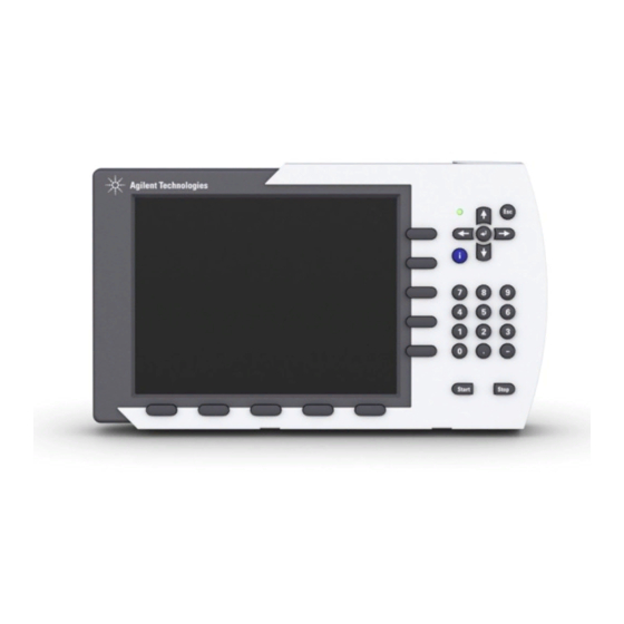
Start-up Information Instant Pilot Features Instant Pilot Features Figure 1 The Agilent Instant Pilot The Agilent Instant Pilot (IP) provides complete local control and monitoring of a single module or an entire Agilent 1100/1200/1260/1290 Series HPLC system. You have easy access to every supported function, you can easily control all parameters and settings and you can configure various communication channels with other devices, in order to comfortably analyze the generated data. - Page 9 Start-up Information Instant Pilot Features • Protect your method from any inadvertent keyboard changes by setting method file protection. • Use USB Flash Drive to store and transfer methods and sequences between Agilent systems. • Monitor all operations and error events using the self- updating logbooks. •...
-
Page 10: Features And Benefits
Start-up Information Features and Benefits Features and Benefits Table 1 Features and Benefits Feature Benefit • Large size, color display with background light, high reso- Better readability and usability. lution and contrast • USB port / USB Flash Drive Faster and more flexible method and sequence transfer to other Agilent systems. -
Page 11: Requirements For The Instant Pilot
Start-up Information Requirements for the Instant Pilot Requirements for the Instant Pilot The Agilent Instant Pilot can be attached to a modular Agilent HPLC system or a single Agilent HPLC module. Depending on the system, the following firmware requirements must be fulfilled. Table 2 Pre-requisites / Compatibility vs. - Page 12 Start-up Information Requirements for the Instant Pilot Since USB Flash Drives may vary from vendor to vendor or from type to type, NOTE incompatibilities can occur. In general, USB Flash Drives from Sandisk and Kingston should work. The USB Flash Drive must be FAT-16 formatted and without encryption.
-
Page 13: Physical Specifications
Start-up Information Physical Specifications Physical Specifications Table 3 Physical Specifications Type Specification Comments Weight 0.8 kg (1.76 lbs) Dimensions 130 × 225 × 35 mm (width × depth × height) (5.1 × 8.9 × 1.4 inches) Line voltage 22 VDC, ± 10 % via CAN Power consumption Ambient operating temperature 4 –... -
Page 14: Cleaning
Start-up Information Cleaning Cleaning To keep the module case clean, use a soft cloth slightly dampened with water, or a solution of water and mild detergent. Liquid dripping into the electronic compartment of your module can cause WAR N IN G shock hazard and damage the module Do not use an excessively damp cloth during cleaning. -
Page 15: Holder Versions For The Instant Pilot
Start-up Information Holder Versions for the Instant Pilot Holder Versions for the Instant Pilot Mid of 2007, the holder of the Instant Pilot was introduced with a revised design. Features of new holder are • easy to use • safe placement of the Instant Pilot •... -
Page 16: Adding The Instant Pilot To An Agilent Hplc Module
Start-up Information Adding the Instant Pilot to an Agilent HPLC Module Adding the Instant Pilot to an Agilent HPLC Module The CAN connectors are similar to LAN adapter connectors C AU T I O N Do not insert LAN connectors into the CAN or vice versa, since the CAN ... -
Page 17: Adding The Instant Pilot To An Agilent Hplc Module (1100/1200/1200 Infinity Series)
Start-up Information Adding the Instant Pilot to an Agilent HPLC Module Adding the Instant Pilot to an Agilent HPLC Module (1100/1200/1200 Infinity Series) Slide the adapter plate (delivered with the Instant Pilot) Assure that it is fixed by pressing onto the adapter from the front onto the top cover of the Agilent HPLC plate. -
Page 18: Adding The Instant Pilot To An Agilent Hplc Module (1200 Infinity Ii Series)
Start-up Information Adding the Instant Pilot to an Agilent HPLC Module Adding the Instant Pilot to an Agilent HPLC Module (1200 Infinity II Series) Preparations Content of Holder Infinity II Kit The kit 5067- 5955 (part of the Instant Pilot G4208A from May 2015) includes •... - Page 19 Start-up Information Adding the Instant Pilot to an Agilent HPLC Module Fix the holder with the screw. Re-install the Leak Interface Top and the door. Insert the Instant Pilot into the holder. Connect the CAN cable of the Instant Pilot into a free CAN connector at the rear of the module.
-
Page 20: Removing The Instant Pilot
Start-up Information Removing the Instant Pilot Removing the Instant Pilot The CAN bus does not support hot plugging or unplugging. C AU T I O N Unwanted or unexpected behavior of the instrument. Switch off all HPLC modules, before plugging/unplugging the Instant Pilot. ... -
Page 21: Instant Pilot Display And Keyboard Layout
Start-up Information Instant Pilot Display and Keyboard Layout Instant Pilot Display and Keyboard Layout Figure 4 on page 21 shows the layout of the display and the keys. All has been arranged in functional groups around the display. Figure 4 The Agilent Series Instant Pilot - Layout The displayed module’s naming may change depending on the installed NOTE... - Page 22 Start-up Information Instant Pilot Display and Keyboard Layout Table 4 Instant Pilot Display and Keyboard Layout Item Key Group Description Action keys trigger a variety of functions. The available functions depend on the screen you are working with. Navigation keys allow you to switch between the dialogs.
-
Page 23: The I (Info) Key - Online Information System
Start-up Information The i (info) key - Online Information System The i (info) key - Online Information System The online information system provides a quick and convenient way to look up information about a task you are doing or a feature or screen you would like to know more about. - Page 24 Start-up Information The i (info) key - Online Information System Figure 6 Online Information System - Content (left) / Home (right) Figure 7 Online Information System - Index (left) / Details (right) G4208A User’s Guide...
- Page 25 Start-up Information The i (info) key - Online Information System Table 5 Online Help - Functions of Keys Button Description OK key or 8 navigates to the selected (focussed) link exits the online help ← or → moves the curser to previous or next link ↑...
-
Page 26: Basic Operational Concept Of The Instant Pilot
Start-up Information Basic Operational Concept of the Instant Pilot Basic Operational Concept of the Instant Pilot Below is the new operation concept of the Instant Pilot described. Configuration These parameters allow setup of the instrument configuration. Typically, these configurations are linked to properties of the instrument (e.g. module names, flow path volumes, analog output configuration, LAN address) that are set up only at installation or after modification of the instrument setup. -
Page 27: Getting Started
Start-up Information Getting Started Getting Started If additional details are required on a specific topic/function/parameter not NOTE mentioned in this document, please use the Instant Pilot’s Online Information System (i), see “The i (info) key - Online Information System” on page 23. 1 Start the Instant Pilot. - Page 28 Start-up Information Getting Started 2 Select Continue to continue the setup. Select Abort to close the Setup Wizard. The next setup screens allow you to change the Date & Time, Units & Formats and the Display. Use the Direction keys for moving to the fields and Edit or OK to open the selection fields.
- Page 29 Start-up Information Getting Started 4 Select Next to enter a system name. System name can be entered Figure 9 Getting Started - Setting a System Name A system name will be displayed on screens and printouts as identifier. G4208A User’s Guide...
- Page 30 Start-up Information Getting Started 5 Select Next to define units and formats. 24/12 h Month/Day/Year Day.Month.Year Bar / PSI / kPa Celsius / Fahrenheit / Kelvin Figure 10 Getting Started - Setup Wizard - Units & Formats 6 Select Next to define display settings After 1 / 10 / 30 / 60 minutes / No shutoff 10 / 20 / 30 / 40 / 50 / 60 /...
- Page 31 Start-up Information Getting Started 7 Select Next to view LAN settings. The next screen shows the LAN settings of an additional MIO card that has been identified in the system (may not been connected to LAN). allows modifications of the settings.
- Page 32 Start-up Information Getting Started 9 Select Exit to close the setup. Finally, the Welcome or the Configuration screen is displayed. Figure 14 Getting Started - Welcome Screen The next time the Instant Pilot is started, it will start with the Welcome screen. To activate the setup wizard again, select More>...
-
Page 33: System Information
Start-up Information System Information System Information 1 To gather information about the Instant Pilot and the Agilent modules, press the Details button from the Welcome screen. updates the displayed information prints the displayed information to the USB Flash Drive leaves the screen Figure 15 Getting Started - System Info The screen contains information about serial numbers and firmware... -
Page 34: Method Information
Start-up Information Method Information Method Information 1 To view/edit the method information, press the Method button from the Welcome screen. on-line information in edit-mode the limits are shown Figure 16 Method Screen The screen displays complete or filtered information about module settings and parameters of all modules. - Page 35 Start-up Information Method Information Table 6 Method - Functions of Keys Button Description Edit or OK lets you edit a parameter field Control opens a menu to control certain module/system activi- ties (depends on the connected modules). Toggle switches between filtered and unfiltered view. Exit or Esc exits the method screen Filter...
-
Page 36: Sequence Information
Start-up Information Sequence Information Sequence Information 1 To view/edit the sequence information, press Sequence from the Welcome screen. A sequence consists of a list of items that should be processed from top to bottom. 2 Use the Insert button to insert items in the list. In case of samples and calibration samples use the Wizard to insert items in the list. - Page 37 Start-up Information Sequence Information Table 7 Sequence - Functions of Keys Button Description Edit Insert inserts a new line with an actions from a menu (for details refer to Instant Pilot’s Info System). Delete deletes a selected sequence line Copy copies a selected sequence line Exit or Esc exits the screen...
-
Page 38: Status Information
Start-up Information Status Information Status Information To view/edit the Status information, press Status from the Welcome screen. Figure 17 Status Screen (Default/Defined) The Status screen is a configurable overview of the instrument status. You can view actual values/states and edit parameters. The screen is divided into four tiles. - Page 39 Start-up Information Status Information Table 8 Status - Function of Keys Button Description Plot shows different signals of the connected modules over time. The signals are user-selectable, can automatically be rescaled for best on-screen fitting. Setup lets you set up the views. Select one of the last 4 setups can be loaded.
-
Page 40: Setup Of A Status Information Screen
Start-up Information Status Information Setup of a Status Information Screen When the Status Information screen has not been setup before, it will show from each module in the system one or more signals/parameters (default). 1 Press the Setup button. allows the selection of a signal/parameter clears a selected field cuts a selected field to be... - Page 41 Start-up Information Status Information leave this screen without changes select a signal/parameter Figure 19 Status Screen (Select) 3 From this list select a signal/parameter and press Select. The selection will be taken for the selected window. Figure 20 on page 41 shows the relation of the windows in the Setup screen versus displayed windows.
- Page 42 Start-up Information Status Information 4 Press Properties on the Setup screen to access the history of the current status view changes and the protection of the status view. protect/unprotect a status view with a password leaves this screen without changes select a signal/parameter Figure 21 Status Screen (Properties / History)
-
Page 43: Logbook Information
Start-up Information Logbook Information Logbook Information 1 To view/change the Logbook information, press Logbook from the Welcome screen. to define what is displayed opens a menu to control certain system activities prints the logbook to a file on the USB Flash Drive leaves this screen system or module specific information... - Page 44 Start-up Information Logbook Information Table 9 Legend of Logbook Icons/Entries Icon Event status change event Info event error event EMF (Early Maintenance Feedback) event sequence event Figure 24 Logbook Screen - saved to USB Flash Drive G4208A User’s Guide...
-
Page 45: Configuration
Start-up Information Configuration Configuration 1 To view/change the configuration, press More from the Welcome screen and select Configuration from the menu. to change the settings opens the Setup Wizard leaves this screen system or module specific information Figure 25 Configuration of System 2 To change the system configuration, move to the line you want to change and press Edit. -
Page 46: Maintenance Information
Start-up Information Maintenance Information Maintenance Information The Instant Pilot provides basic maintenance and diagnostic functions only. The NOTE Agilent LabAdvisor software provides the full maintenance and diagnostic capabilities. 1 To view/change the Maintenance information, press More from the Welcome screen and select Maintenance from the menu. update a single module update a set of modules to change the product number... - Page 47 Start-up Information Maintenance Information 3 Press the Exit button or Esc key to leave the screen. EMF setup select maintenance activity Identify - module LED blinks Figure 27 Maintenance Screen - Pump select maintenance activity from list saves the maintenance activity Figure 28 Maintenance Screen - Select Maintenance Activity G4208A User’s Guide...
-
Page 48: Early Maintenance Feedback (Emf)
Start-up Information Maintenance Information Early Maintenance Feedback (EMF) In case you have set the EMF limits and the limit has been reached, a message pops up. Figure 29 Early Maintenance Feedback (EMF) - Message 1 The limits can be set in the EMF Setup screen. actual, changes the color depending on state: green - below limit... -
Page 49: Product Number And Serial Number Change
Start-up Information Maintenance Information Product Number and Serial Number Change When the main board has to be replaced, the new board does not have a serial NOTE number. For some modules (e.g. pumps or auto samplers) the type has to be changed (multiple usage boards). -
Page 50: Diagnosis Information
Start-up Information Diagnosis Information Diagnosis Information The Instant Pilot provides basic maintenance and diagnostic functions only. The NOTE Agilent LabAdvisor software provides the full maintenance and diagnostic capabilities. 1 To perform a module- specific test, press More from the Welcome screen and select Diagnosis from the menu. -
Page 51: Turning Modules On/Off/Standby
Start-up Information Turning Modules ON/OFF/Standby Turning Modules ON/OFF/Standby 1 To switch a module ON or OFF or into STANDBY, press Control from the Welcome/Method/Status/Logbook screen. Turns the pumps ON Turns the heater ON Turns the lamps ON Turns all ON Leaves this screen Module specific tasks: e.g. -
Page 52: Start Analysis Screen
Start-up Information Start Analysis Screen Start Analysis Screen With firmware revision B.02.01 and A.05.11 (November 2006) the Start Analysis screen, known from the G1323B Control Module, has been enhanced. It allows to set up a simple analysis by • pressing the START key •... -
Page 53: Switching From G1323A/B Control Module To Instant Pilot
Start-up Information Switching from G1323A/B Control Module to Instant Pilot Switching from G1323A/B Control Module to Instant Pilot The Instant Pilot is a further development of the G1323A/B Control Module which has been reworked and structured in a new modern way (more like an Agilent ChemStation). - Page 54 Start-up Information Switching from G1323A/B Control Module to Instant Pilot Table 10 G1323A/B Control Module vs. Instant Pilot Functions G1323A/B Control Module G4208A Instant Pilot Comment Status screen Welcome screen - Status Plot screen Welcome screen - Status - Plot Spectrum (DAD/MWD/VWD/FLD) Control button (on various screens) G4208A User’s Guide...
-
Page 55: Information On Firmware
Start-up Information Information on Firmware Information on Firmware Use always the latest version of the Instant Pilot firmware. It is always backward compatible with all previously released versions. • A.05.15 or later for firmware platform A.05xx • Update main part only. •... -
Page 56: Working With The Instant Pilot
Working with the Instant Pilot Using a USB Flash Drive Handling of Unsupported USB Flash Drive Formats Printing To USB Flash Drive Working with Methods Loading a Method Modifying a Method Filtering Method Information Compare Methods Method Timetable Method Properties Method File Protection Saving a Method Transfer of Methods... -
Page 57: Using A Usb Flash Drive
Working with the Instant Pilot Using a USB Flash Drive Using a USB Flash Drive You can use many USB Flash Drive with USB 1.1 support that can be physically inserted while the Instant Pilot is attached to the Agilent system. Since USB Flash Drives may vary from vendor to vendor or from type to type, NOTE incompatibilities can occur. -
Page 58: Handling Of Unsupported Usb Flash Drive Formats
Working with the Instant Pilot Using a USB Flash Drive Handling of Unsupported USB Flash Drive Formats If a unsupported format on a newly inserted USB Flash Drive is found, the Instant Pilot brings up a warning and asks the user to format the drive in a proper way. Figure 35 Unsupported USB Flash Drive 1 When selecting "No", theUSB Flash Drive will be ignored/can not be used in... -
Page 59: Printing To Usb Flash Drive
Working with the Instant Pilot Printing To USB Flash Drive Printing To USB Flash Drive There is no direct printing via a printing device connected to the 1100/1200/1260/1290 system possible. But certain information can be printed to a file that is saved to an USB Flash Drive into a folder PRINTOUT. The files are of type .MHT or .HTM, depending on the setting in Configuration>... - Page 60 Working with the Instant Pilot Printing To USB Flash Drive Figure 37 Example of a Printed Document - Instrument Logbook The following information can be "printed". G4208A User’s Guide...
- Page 61 Working with the Instant Pilot Printing To USB Flash Drive Table 11 Overview of Printable Information PRINT- Dialog Name Button Comment File Name in System Details Print SYSINFO.MHT via Details button, see Figure 37 on page 60 Method File - Print METHOD.MHT Contains Method, Timetable, Inj.Programm Sequence File - Print SEQUENCE.MHT...
- Page 62 Working with the Instant Pilot Printing To USB Flash Drive Table 11 Overview of Printable Information PRINT- Dialog Name Button Comment File Name in Pressure Tests • ISO Pump, Bin Pump, Micro Print DIAGRES.MHT Pump Normal, Quad Press • High Flow Pump Press Print DIAGRES.MHT •...
- Page 63 Working with the Instant Pilot Printing To USB Flash Drive system name, date name of test/plot module / serial number plot actions results sign-off Figure 38 Example of a Printed Document - DAD Holmium Test G4208A User’s Guide...
-
Page 64: Working With Methods
Working with the Instant Pilot Working with Methods Working with Methods If additional details are required on a specific topic/function/parameter not NOTE mentioned in this document, please use the Instant Pilot’s Online Information System (i), see “The i (info) key - Online Information System” on page 23. -
Page 65: Loading A Method
Working with the Instant Pilot Working with Methods Loading a Method A method can be loaded pressing File in the Method screen: 1 Enter the Method screen. 2 The current parameters are displayed. 3 Press File. 4 Select option 1 - Load. 5 Select a method from the list. -
Page 66: Modifying A Method
Working with the Instant Pilot Working with Methods Modifying a Method A method can be modified by changing the settings in the Method screen. 1 Scroll to the line you want to change. 2 Press Edit or OK. 3 Enter the new value. 4 Press Done. -
Page 67: Filtering Method Information
Working with the Instant Pilot Working with Methods Filtering Method Information When a Filter is selected, only the parameters that are selected in this filter are shown on the Method screen. Selects/de-selects the parameter Selects all parameter De-selects all parameter Exits this screen Saves the settings and leaves the screen... -
Page 68: Compare Methods
Working with the Instant Pilot Working with Methods Compare Methods The Compare screen is a tool that allows you to compare two methods. The differences are shown in a list by displaying the values from both methods side by side. You can copy parameters between the two selected methods using the Copy function. -
Page 69: Method Timetable
Working with the Instant Pilot Working with Methods Method Timetable To time- program selected settings during the analysis, you can create a timetable. Using the Timetable screen, you can create a time- based program that will automatically control the modules of a system and external contacts (if an external contact board is used). - Page 70 Working with the Instant Pilot Working with Methods A timetable line can be inserted by pressing Insert and consists of the following: • Time Set the time span between the instant of injection and the desired parameter change. • Setting Select the parameter to be changed.
-
Page 71: Method Properties
Working with the Instant Pilot Working with Methods Method Properties The properties of a method can be reviewed in the Properties screen. The user can view change history. • The method’s name. This string is used as unique identification of the method and is also used as the filename. -
Page 72: Method File Protection
Working with the Instant Pilot Working with Methods Method File Protection With firmware revsion B.02.05 (May 2007) several additional checks and disabling of functions were added to ensure protected file security - online and offline: • If a file is protected, the user can not edit the currently loaded method content or its filter settings. - Page 73 Working with the Instant Pilot Working with Methods A password to protect a file can have up to 12 digits. If left empty, no/empty password will be added to the file protection. Figure 47 Method - Protection Figure 48 Method - Properties / History G4208A User’s Guide...
-
Page 74: Saving A Method
Working with the Instant Pilot Working with Methods Saving a Method Methods are stored within the Instant Pilot (internal memory) and/or on an external USB Flash Drive. The currently loaded method is also the active method in the modules. Changes to the method are immediately transfered to the modules. - Page 75 Working with the Instant Pilot Working with Methods 1 Press File and select the Save as. Figure 50 Method - Save As 2 Choose the location (internal = Instant Pilot or USB = USB Flash Drive) and a name (if not already done). 3 You may delete or copy methods from one location to the other.
-
Page 76: Transfer Of Methods
Working with the Instant Pilot Working with Methods Transfer of Methods The File Transfer dialog allows you to transfer files between internal file storage and the connected USB Flash Drive. Deletes a method Copies a method Protect/unprotect the method Transfers the method Exits this screen Figure 51 Method - Transfer... -
Page 77: Offline Work On Methods
Working with the Instant Pilot Working with Methods Offline Work on Methods The Import dialog gives you the ability to edit methods offline. It is possible to edit methods that were not actually loaded onto the modules. The offline method dialog starts with a copy of the actual method. -
Page 78: Import Of Methods
Working with the Instant Pilot Working with Methods Import of Methods This functions allows the import of G1323 Control Module methods stored on the instrument or on the USB Flash Drive. Export is not possible. Imports a selected method Deletes a method Exits the screen Figure 53 Method - Import... -
Page 79: Injector Program
Working with the Instant Pilot Working with Methods Injector Program With firmware revisions B.02.01 and A.05.11 (November 2006) the Injector Program has been implemented. The injector program is part of the method. The injector program screen can be accessed by pressing edit on the Injection Mode line and change it to Injector Program in the Method view. - Page 80 Working with the Instant Pilot Working with Methods 1 Press the Default button to start with a pre-defined injector program. This can be modified or expanded. Figure 54 Injector Program - Default Program 2 Move to a line of the Injector Program and press Edit button to view the current settings or start a new line.
- Page 81 Working with the Instant Pilot Working with Methods 3 Press the Insert button and select an action item. Figure 56 Injector Program - Setup Screen 4 Move to line End of User Defined Injector Program, press the Insert button and select additional action items as required.
- Page 82 Working with the Instant Pilot Working with Methods Table 12 Insertable/Editable Injector Program Lines Command Comment Draw default amount from sample (from actual position) Draw default amount from sample plus x vial(s) from actual position Draw x μl from vial y Draw x μl from seat Draw x μl from air Draw x μl from flush...
- Page 83 Working with the Instant Pilot Working with Methods Table 12 Insertable/Editable Injector Program Lines Command Comment Remote ready Remote not ready Remote start Wait x minutes Wait for ready, timeout x min Wait for start, timeout x min Contact x open/close Repeat Start, x times Repeat End Increment actual sample position + x vial(s)
-
Page 84: Sequence - Automating Analyses
Working with the Instant Pilot Sequence - Automating Analyses Sequence - Automating Analyses If additional details are required on a specific topic/function/parameter not NOTE mentioned in this document, please use the Instant Pilot’s Online Information System (i), see “The i (info) key - Online Information System” on page 23. - Page 85 Working with the Instant Pilot Sequence - Automating Analyses Insert a line (for details refer to Instant Pilot’s Info System). Figure 59 Sequence - Add a sequence line At the end of the sequence, you can specify either to load a method (e.g. to flush the LC system to remove buffer salts to avoid crystallization or to program a soft shut-down method) using Insert/Method or turn OFF the LC system using End Actions.
-
Page 86: Using The Sequence Wizard
Working with the Instant Pilot Sequence - Automating Analyses Using the Sequence Wizard You may use the Wizard to set up a sequence. Figure 60 Sequence Wizard - Adding Samples Information Figure 61 Sequence Wizard - Adding Calibration Information Figure 62 on page 87 and Figure 63 on page 87 for effect of selection “Multi”... - Page 87 Working with the Instant Pilot Sequence - Automating Analyses Figure 62 Sequence Wizard - Preview with Calibration Parameter Multi Figure 63 Sequence Wizard - Preview with Calibration Parameter Alternate G4208A User’s Guide...
-
Page 88: Saving A Sequence
Working with the Instant Pilot Sequence - Automating Analyses Saving a Sequence Sequences are stored within the Instant Pilot (internal memory) and/or on an external USB Flash Drive. The sequence is only in the controller. Changes to a sequence line can be when the line is not active (if sequence is running). The Instant Pilot generates a list of all available sequences that can be loaded. - Page 89 Working with the Instant Pilot Sequence - Automating Analyses 1 Press File and select the Save as. 2 Choose the location (internal = Instant Pilot or USB = USB Flash Drive) and a name (if not already done). Deletes a sequence Copies a sequence Protect/unprotect the sequence...
-
Page 90: Sequence - File Protection
Working with the Instant Pilot Sequence - Automating Analyses Sequence - File Protection You may protect/un- protect a sequence (see “Method Properties” on page 71 “Method File Protection” on page 72). Differences are: • Edit, Insert, Delete, Copy, Wizard and Save buttons are disabled. •... -
Page 91: Tray View
Working with the Instant Pilot Sequence - Automating Analyses Tray View The current sequence's status is shown graphically. The sequence samples are shown at their locations on the tray using colors representing their states. Green already processed sample Blue sample to process Magenta calibration sample Yellow... -
Page 92: Starting And Stopping A Sequence
Working with the Instant Pilot Sequence - Automating Analyses Starting and Stopping a Sequence When you press Start, the Start Analysis dialog pops up where you can select between • setting up a sample range, • starting the current (saved) sequence or •... - Page 93 Working with the Instant Pilot Sequence - Automating Analyses Press Status to display the actual system status. If any activities before the system ready (gray status) are still required, press Continue and all actions (e.g. required lamps are turned on) are performed automatically.
- Page 94 Working with the Instant Pilot Sequence - Automating Analyses Sequence status Figure 69 Sequence - Status When you press Stop, the Stop Analysis dialog pops up where you can select between aborting immediately or pausing the sequence. Continue aborts or pauses —...
-
Page 95: Displaying Data Graphically
Working with the Instant Pilot Displaying Data Graphically Displaying Data Graphically The Plot screen gives you many opportunities to display a wide variety of signals on a graphic display while the analysis is performed or not. The plot screen can show different signals of the connected modules over time. -
Page 96: Setup Of Signals
Working with the Instant Pilot Displaying Data Graphically Setup of Signals Up to four of the available signals can be chosen for graphical display. 1 From the Plot screen, press Setup to show the Selection screen. 2 Use the Direction and Selection keys to navigate within — and between the available signals and selected signals list boxes. -
Page 97: Rescaling The Plot Screen
Working with the Instant Pilot Displaying Data Graphically Rescaling the Plot Screen Figure 73 Plot screen - Setup signals Press Rescale and select the signal. X (time) axis To rescale the X (time) axis, use the Direction keys (left/right). Y (signal unit) axis There are several possibilities to rescale the Y (signal unit) axis: •... -
Page 98: Dad/Mwd/Vwd/Fld Spectrum
Working with the Instant Pilot DAD/MWD/VWD/FLD Spectrum DAD/MWD/VWD/FLD Spectrum Via the Control button and More, the DAD/MWD/VWD/FLD spectrum screen is accessible. Single spectrum starts continuous spectrum stops continuous spectrum prints spectrum to USB Flash Drive exits the screen Figure 74 Spectrum - Example DAD The scan range and step width can be set. -
Page 99: Fld Spectrum
Working with the Instant Pilot DAD/MWD/VWD/FLD Spectrum FLD Spectrum Under Control/More the user has two additional options: Excitation Spectrum and Emission Spectrum. Both screens are similar, only the editable parameters are different according the selected spectra type (see Figure 75 on page 99). - Page 100 Working with the Instant Pilot DAD/MWD/VWD/FLD Spectrum Warnings are shown, if the method parameters are not set to produce spectra information and if the lamp in not switched on. Start keys will be kept disabled until valid conditions are reached. Figure 77 Spectrum - FLD G4208A User’s Guide...
-
Page 101: Connecting External Devices
Working with the Instant Pilot Connecting External Devices Connecting External Devices There are several kinds of interface that enable the Agilent Series modules to communicate with a range of other output devices. For some of them, extra hardware needs to be installed. Configuration of selected interface parameters is possible and is handled individually for each module, since some interfaces are only available with certain modules (depending on installation). -
Page 102: Bcd
Working with the Instant Pilot Connecting External Devices Ready When all Agilent Series modules are ready for the next analysis, this signal is on. Other modules or external devices can now react (e.g. by issuing a start request). Prepare This causes the modules to get ready for the next analysis (e.g. the detector performs a balance). -
Page 103: Communication Interfaces
Working with the Instant Pilot Connecting External Devices Communication Interfaces See also “Simultaneous Execution with Software” on page 104 for further details on how to operate the system using the GPIB interface. The module to module communication is done via CAN. MIO / LAN This interface enables the Agilent Series modules to communicate with PCs configured as CDS using a local area network (LAN). -
Page 104: Simultaneous Execution With Software
Working with the Instant Pilot Simultaneous Execution with Software Simultaneous Execution with Software With Agilent ChemStation Features • All user interfaces, the Instant Pilot, the Agilent ChemStation or the Agilent Cerity WorkStation and OpenLab, can be connected to an Agilent Series system at the same time. - Page 105 Working with the Instant Pilot Simultaneous Execution with Software accessible from the Agilent ChemStation). To have a method available on both controllers, proceed as follows: If the method is on the Agilent ChemStation and should be saved on the Instant Pilot or USB Flash Drive, load the method on Agilent ChemStation and then save the method on the Instant Pilot (or USB Flash Drive) with Method —...
-
Page 106: With 3Rd Party Control Software
Working with the Instant Pilot Simultaneous Execution with Software With 3 Party Control Software There may be problems when connecting the Agilent Instant Pilot G4208A to an Agilent 1100/1200//1260/1290 instrument controlled by third party software, if this software generates an error when detecting an unknown module in the configuration. -
Page 107: Special Functions
Working with the Instant Pilot Special Functions Special Functions Saving a Screenshot to USB Flash Drive You may want to create a screenshot for • adding it to a documentation or • troubleshooting reasons. To do so, 1 Insert the USB Flash Drive. 2 Wait until the USB Flash Drive has been initiated. -
Page 108: Running An Isocratic Analysis
Preparing the LC System Entering Settings Saving Settings in a Method Creating a Sequence Selecting a Signal Observing the Chromatogram This chapter describes how to analyze the Agilent Technologies isocratic standard sample using a single injection analysis. G4208A User’s Guide... -
Page 109: What You Will Need
Agilent Series isocratic, binary or quaternary pump, an autosampler and a UV- detector. Column A 125 mm × 4.0 mm Hypersil ODS, 5 μm (Agilent Technologies part number 7982618- 564). Solvents For the isocratic pump, a solvent mixture of LC grade bidistilled water (35 %) and acetonitrile (65 %). -
Page 110: Preparing The Lc System
5 Allow the detector at least 15 min to provide a stable baseline. 6 Transfer the contents of an Agilent Technologies isocratic standard sample ampoule into a vial and seal the vial with a cap. Place the vial in position 1 of the autosampler tray. -
Page 111: Entering Settings
Running an Isocratic Analysis Entering Settings Entering Settings To set up the isocratic analysis, you will set the LC system settings to default and then modify selected settings. The other settings will remain with their default values. You will then save these settings to a method called ISO. 1 Enter the Method screen. -
Page 112: Saving Settings In A Method
Running an Isocratic Analysis Saving Settings in a Method Saving Settings in a Method 1 Select File in the Method Information screen. 2 Select “Save As”. 3 Enter the method name as ISO using the selection keys (also see “Method File Protection”... -
Page 113: Creating A Sequence
Running an Isocratic Analysis Creating a Sequence Creating a Sequence 1 Select Sequence in the Welcome screen. 2 Press Insert and select Method. 3 Select Method named and press OK. 4 Press Insert and select Sample. If your sample is not in vial 1, you have to modify the vial number (also see “Sequence - Automating Analyses”... -
Page 114: Selecting A Signal
Running an Isocratic Analysis Selecting a Signal Selecting a Signal 1 Setup the signal parameters in the Method Information screen. 2 Select Status in the Welcome screen. 3 Press Plot. 4 Press Setup. 5 Choose a Detector Signal from the Available Signals list. You can choose several signals at a time. -
Page 115: Observing The Chromatogram
Running an Isocratic Analysis Observing the Chromatogram Observing the Chromatogram 1 Select the Status screen. 2 Press Start. 3 Select Continue to confirm the start of the analysis. 4 If the system is not ready (yellow), you have to press Continue again. The modules automatically get ready and start the analysis. -
Page 116: Running Multiple-Vial Analyses
Running Multiple-Vial Analyses Analyzing Multiple Vials Using the Same Method Analyzing Multiple Vials Using Different Methods Single-Level Calibration Sequences Multiple-Level Calibration Sequences Re-calibrating With the Same Group of Standards Re-calibrating With Multiple Groups of Standards Synchronizing Analyses with External Devices Standard Mode Send Single Start Request Send Multiple Start Request (external controlled injector) -
Page 117: Analyzing Multiple Vials Using The Same Method
Running Multiple-Vial Analyses Analyzing Multiple Vials Using the Same Method Analyzing Multiple Vials Using the Same Method This section describes how to set up a 25- vial analysis with one injection from each vial. You will use a previously created method. The samples are located in positions 1 to 25 of the autosampler tray. -
Page 118: Analyzing Multiple Vials Using Different Methods
Running Multiple-Vial Analyses Analyzing Multiple Vials Using Different Methods Analyzing Multiple Vials Using Different Methods This section describes how to set up a 50- vial analysis using three methods which you have previously created called e.g. METH1, METH2 and METH3. For example: METH1 and METH2 have the same analytical settings but differ in the injection volume and stoptime values. - Page 119 Running Multiple-Vial Analyses Analyzing Multiple Vials Using Different Methods 10 Move to the End of sequence list and select Insert. 11 Select Method and then move to METH3 and press Load. 12 Move to the End of sequence list and select Insert. 13 Select Wait time and enter: Wait 30 min...
-
Page 120: Single-Level Calibration Sequences
Running Multiple-Vial Analyses Single-Level Calibration Sequences Single-Level Calibration Sequences The following procedure describes how to set up a calibration sequence for an analysis which uses single- level calibration. There is one calibration standard (C) and 9 samples (S). The analysis requires that: •... - Page 121 Running Multiple-Vial Analyses Single-Level Calibration Sequences 6 Change the settings according to Figure 80 on page 121. Figure 80 Sequence Calibration Wizard G4208A User’s Guide...
- Page 122 Running Multiple-Vial Analyses Single-Level Calibration Sequences 7 Press Preview to view the result. Figure 81 Sequence Calibration Wizard - Preview 8 Select Done to accept entries. 9 Press Start and confirm the start of the sequence. G4208A User’s Guide...
-
Page 123: Multiple-Level Calibration Sequences
Running Multiple-Vial Analyses Multiple-Level Calibration Sequences Multiple-Level Calibration Sequences The following sections describe how to set up calibration sequences for analyses which use multiple- level calibration. Re-calibrating With the Same Group of Standards There are three calibration standards of different concentrations (C1, C2, C3) and 15 samples (S). - Page 124 Running Multiple-Vial Analyses Multiple-Level Calibration Sequences 6 Change the settings according to Figure 82 on page 124. Figure 82 Sequence Calibration Wizard 7 Press Preview to view the result. Figure 83 Sequence Calibration Wizard - Preview G4208A User’s Guide...
- Page 125 Running Multiple-Vial Analyses Multiple-Level Calibration Sequences 8 Select Done to accept entries. 9 Press Start and confirm the start of the sequence. The autosampler now analyzes: • the three calibration standards in duplicate, • sample vials 10 through 14, • the three calibration standards in duplicate, •...
-
Page 126: Re-Calibrating With Multiple Groups Of Standards
Running Multiple-Vial Analyses Re-calibrating With Multiple Groups of Standards Re-calibrating With Multiple Groups of Standards There are two different types of sample, A and B that need to be analyzed. The analysis for sample type A requires a 5 μl injection and a stoptime of 8 minutes. The analysis of sample type B requires a 2 μl injection and a stoptime of 5 minutes. - Page 127 Running Multiple-Vial Analyses Re-calibrating With Multiple Groups of Standards 4 Move to the End of sequence list, select the Wizard and enter: Vial Range 7 to 12 #Inj. 5 Select Calibration to display the Calibration Settings screen. 6 Change the settings according to Figure 84 on page 127.
- Page 128 Running Multiple-Vial Analyses Re-calibrating With Multiple Groups of Standards 13 Change the settings according to Figure 85 on page 128. Figure 85 Sequence Calibration Wizard 14 You may press Preview to view the result. 15 Select Done to accept entries. 16 Press Start and confirm the start of the sequence.
-
Page 129: Synchronizing Analyses With External Devices
Running Multiple-Vial Analyses Synchronizing Analyses with External Devices Synchronizing Analyses with External Devices With an APG remote connector the system can be connected to external devices in order to synchronize the analyses. This is necessary when an external device needs some time in order to get ready for a new analysis and when transmission of a start request is required (see “Connecting External Devices”... -
Page 130: Standard Mode
Running Multiple-Vial Analyses Synchronizing Analyses with External Devices Standard Mode In the standard mode, the analysis is under the command of the Instant Pilot. The Instant Pilot issues a Start command to the autosampler as soon as all modules are ready for the next analysis. The autosampler issues the Start command at the point of injection. -
Page 131: Send Multiple Start Request (External Controlled Injector)
Running Multiple-Vial Analyses Synchronizing Analyses with External Devices Send Multiple Start Request (external controlled injector) This will cause the Instant Pilot to generate start requests before each run. The external device starts each injection then by sending a start signal to the APG remote line. -
Page 132: Wait For Single (External) Start Request
Running Multiple-Vial Analyses Synchronizing Analyses with External Devices Wait for Single (External) Start Request After pressing the Start button, the Instant Pilot waits for a single external start request on the APG remote lines. When the start request is received, the complete vial range or sequence is done as in standard mode under the command of the Instant Pilot without further external synchronization. -
Page 133: Wait For Multiple Start Request (Instant Pilot Controls Injector)
Running Multiple-Vial Analyses Synchronizing Analyses with External Devices Wait for Multiple Start Request (Instant Pilot controls injector) After pressing the Start button, the Instant Pilot waits for an external start requests before injection or sequence. The start requests have to be generated by the external device. - Page 134 Running Multiple-Vial Analyses Synchronizing Analyses with External Devices An Agilent variable wavelength detector or diode array detector will perform a NOTE balance (assumed that Auto Balance is set to pre-run) when receiving a start command from the Instant Pilot. This will only happen in the Standard and Wait for single (multiple) start request modes.
-
Page 135: Maintenance And Repair
Maintenance and Repair Firmware Updates Updating the Firmware Using The Single Mode Updating the Firmware Using The Wizard Update Information for A.05.15 Firmware Using the Instant Pilot Using the Agilent Lab Advisor Using the LAN/RS-232 Firmware Update Tool Errors During Firmware Updates Troubleshooting Troubleshooting the Instant Pilot USB Flash Drive not recognized... -
Page 136: Firmware Updates
Maintenance and Repair Firmware Updates Firmware Updates The Agilent HPLC modules and the Instant Pilot have firmware installed that will be updated from time to time to add new features and/or remove malfunctions. The firmware of the instrument consists of two independent sections: •... - Page 137 Maintenance and Repair Firmware Updates Table 13 Firmware Update Tools Update via Module Instant Pilot G4208A LAN/RS-232 Update Tool Lab Advisor B.02.06 and 2.10 and a PC with LAN or above and a PC with RS-232 LAN/RS-232/USB Instant Pilot G4208A USB Flash Drive via the HPLC system plus via the HPLC system plus...
-
Page 138: Updating The Firmware Using The Single Mode
Maintenance and Repair Firmware Updates Updating the Firmware Using The Single Mode Only one firmware revision (set) should be stored on the USB Flash Drive. If more NOTE than one firmware version for a module is available, the Instant Pilot always takes the most recent firmware version. - Page 139 Maintenance and Repair Firmware Updates 3 Press Single. Figure 92 Firmware Update Screen - Ready for Update 4 Press Cont. button to confirm, and Cont. start the update or Cancel to exit this screen. The actions and the progress is shown. Update Information When finished press Exit Figure 93...
-
Page 140: Updating The Firmware Using The Wizard
Maintenance and Repair Firmware Updates Updating the Firmware Using The Wizard Only one firmware revision (set) should be stored on the USB Flash Drive. If more NOTE than one firmware version for a module is available, the Instant Pilot will always take the most recent firmware version. - Page 141 Maintenance and Repair Firmware Updates 3 The next screen (Figure 95 on page 141) shows all modules, their installed firmware revisions and the available firmware revisions on the USB Flash Drive. select/de-select a module clear all selections select all modules exits this screen starts the update active...
-
Page 142: Update Information For A.05.15 Firmware
Maintenance and Repair Firmware Updates Update Information for A.05.15 Firmware Do not downgrade to firmware revsions A.05.13/14. They are not compatible NOTE with G4208A Instant Pilots with serial MY. Before you downgrade to revision A.05.15, upgrade the Instant Pilot to the latest NOTE B.xx.xx firmware revision. -
Page 143: Using The Agilent Lab Advisor
Maintenance and Repair Firmware Updates Using the Agilent Lab Advisor 1 Start The Lab Advisor. 2 Connect to the HPLC system. The modules will be listed. Figure 97 Lab Advisor - System Overview 3 Select Firmware Update. Then lock the system. Figure 98 Lab Advisor - System Overview G4208A User’s Guide... - Page 144 Maintenance and Repair Firmware Updates 4 Set the correct folder for the firmware (1). Select the firmware version for the Instant Pilot (Main and Resident) and/or the other modules. Use always the latest version. (2). Start the Update (3). Figure 99 Lab Advisor - Select the firmware 5 The firmware will be updated and shows the below screen when finished.
-
Page 145: Using The Lan/Rs-232 Firmware Update Tool
Maintenance and Repair Firmware Updates Using the LAN/RS-232 Firmware Update Tool Detailed information about the LAN/RS- 232 Update Tool 2.10 or above can be found within the documentation of this tool provided via the Agilent web at http://www.agilent.com/en-us/firmwareDownload?whid=69761 Use the latest LAN/RS-232 Update Tool 2.10 only NOTE If the Instant Pilot is in “Backward compatible mode ON”, see “With 3rd Party... - Page 146 Maintenance and Repair Firmware Updates Downgrade from B.xx to A.05.1x 1 When the Agilent 1100/1200 series modules are on a firmware platform A.06.xx, downgrade the Instant Pilot to A.05.1x first. During the downgrade process the screen is black. 2 After boot of the Instant Pilot, •...
- Page 147 Maintenance and Repair Firmware Updates Upgrade from A.05.1x to B.xx 1 When the Agilent 1100/1200 series modules are on a firmware platform A.05.09/1x, then update the modules to platform A.06.xx 2 Connect the Instant Pilot (with A.05.1x firmware) to one of the modules (if not already done).
- Page 148 Maintenance and Repair Firmware Updates Upgrade from A.05.11 to A.05.1x If the Instant Pilot needs to be updated with a new firmware revision , follow these steps: 1 Disconnect all 1100/1200 series module from that module that hosts the LAN/RS- 232 interface. 2 Upgrade this module to firmware A.06.xx first (otherwise the Instant Pilot is not visible in the LAN/RS- 232 Update Tool 2.10).
-
Page 149: Errors During Firmware Updates
Maintenance and Repair Firmware Updates Errors During Firmware Updates If an error stops the update process, it is displayed. Figure 102 Firmware Update Screen - Error during the update Press Abort to leave the Update process. In the above example all modules stay in resident mode (blinking yellow). Restart the firmware update again. -
Page 150: Troubleshooting
If the problem still remains, then • power down all connected devices and computers and wait 1 minute and then restart, or • try to use just one Agilent Series module. If the problem still remains, call Agilent Technologies. G4208A User’s Guide... -
Page 151: Usb Flash Drive Not Recognized
Maintenance and Repair Troubleshooting USB Flash Drive not recognized Since USB Flash Drives may vary from vendor to vendor or from type to type, NOTE incompatibilities can occur. In general, USB Flash Drives from Sandisk and Kingston should work. The USB Flash Drive must be FAT-16 formatted and without encryption. -
Page 152: Repairing The Instant Pilot
Maintenance and Repair Repairing the Instant Pilot Repairing the Instant Pilot The Instant Pilot cannot be repaired except for the CAN cable. Parts Identification Table 14 Part Numbers Description Part Number Instant Pilot G4208A (complete assembly) G4208-67001 CAN Cable G4208-81600 Upgrade Kit for NEW HOLDER (for adapting the Instant Pilot to Agilent G4208-68701 1100/1200 series modules, see... -
Page 153: Exchanging The Can Cable
Maintenance and Repair Exchanging the CAN Cable Exchanging the CAN Cable Voltage in the Instant Pilot C AU T I O N Damage to the electronics Before you open the Instant Pilot, the CAN-cable must be disconnected from the HPLC module to assure that no voltages are present in the Instant Pilot. - Page 154 Maintenance and Repair Exchanging the CAN Cable 3 Remove the six screws that fix the rear panel. Figure 103 Rear Panel - location of screws 4 Remove the rear panel carefully. G4208A User’s Guide...
- Page 155 Maintenance and Repair Exchanging the CAN Cable 5 The release button [1] (shown in Figure 104 on page 155) may fall out during the removal. Keep it. Step 5 and 9 are for the OLD rear panel design only. See information on “Adding NOTE the Instant Pilot to an Agilent HPLC Module”...
- Page 156 Maintenance and Repair Exchanging the CAN Cable 10 Carefully replace the rear panel and fit the release button pin into the recess on one end of the connecting rod of the rear panel, see Figure 105 page 156. release button rear panel with recess in rod Figure 105 Pin of release button fits into the recess of the rod (OLD rear panel design) 11 Fix the rear panel screws.
-
Page 157: Appendix
Appendix Safety Information Safety Symbols General Operation Waste Electrical and Electronic Equipment (WEEE) Directive Radio Interference Test and Measurement Agilent Technologies on Internet This chapter provides safety and other general information. G4208A User’s Guide... -
Page 158: Safety Information
Appendix Safety Information Safety Information The following general safety precautions must be observed during all phases of operation, service, and repair of this instrument. Failure to comply with these precautions or with specific warnings elsewhere in this manual violates safety standards of design, manufacture, and intended use of the instrument. -
Page 159: General
Appendix Safety Information General This is a instrument has been manufactured and tested according to international safety standards. Operation Before applying power, comply with the installation section. Additionally the following must be observed. • Do not remove instrument covers when operating. •... -
Page 160: Waste Electrical And Electronic Equipment (Weee) Directive
Appendix Waste Electrical and Electronic Equipment (WEEE) Directive Waste Electrical and Electronic Equipment (WEEE) Directive Abstract The Waste Electrical and Electronic Equipment (WEEE) Directive (2002/96/EC), adopted by EU Commission on 13 February 2003, is introducing producer responsibility on all Electric and Electronic appliances from 13 August 2005. This product complies with the WEEE Directive (2002/96/EC) marking NOTE requirements. -
Page 161: Radio Interference
Appendix Radio Interference Radio Interference Never use cables other than the ones supplied by Agilent Technologies to ensure proper functionality and compliance with safety or EMC regulations. Test and Measurement If test and measurement equipment is operated with equipment unscreened... -
Page 162: Agilent Technologies On Internet
Appendix Agilent Technologies on Internet Agilent Technologies on Internet For the latest information on products and services visit our worldwide web site on the Internet at: http://www.agilent.com G4208A User’s Guide... - Page 163 • Working with the Instant Pilot • Running an Isocratic Analysis • Running Multiple-Vial Analyses • Maintenance and Repair www.agilent.com © Agilent Technologies Inc. 2006-2020 Published in Germany Printed in Malaysia 04/2020 G4208-90010* Part No: G4208-90010 Rev. B Document No: SD-29000124 Rev. B...