Mandik FDMB Manual
Fire dampers
Hide thumbs
Also See for FDMB:
- Manual (87 pages) ,
- Technical documentation manual (49 pages) ,
- Installation and operation manual (48 pages)

Related Manuals for Mandik FDMB


Summary of Contents for Mandik FDMB
-
Page 2: Table Of Contents
These technical specifications state a row of manufactured sizes and models of fire dampers (further only dampers) FDMB. It is valid for production, designing, ordering, delivery, assembly and operation. 1. Description......................... 2. Design..........................3. Communication and control devices………................. 4. Dimensions, weights...................... - Page 3 Fire dampers are shutters in ducts of air-conditioning devices that prevent spreading the fire and combustion products from one fire segment to the other one by means of closing the duct in the points of fire separating constructions. Dampers blade automatically closes air duct using a shutting spring or an actuating mechanism back spring.
- Page 4 Damper characteristics • CE certified acc. to EN 15650 • Tested in accordance with EN 1366-2 • Classified acc. to EN 13501-3+A1 • Fire resistance EIS 120, EIS 90 • External Casing leakage class C, Internal leakage class 2 acc. to EN 1751 •...
- Page 5 Design with mechanical control with a thermal protective fuse which actuates the shutting device within 120 seconds at latest after the nominal start temperature 72 °C has been reached. Automatic initiation of the shutting device is not activated if the temperature does not exceed 70 °C.
- Page 6 Design .01 with mechanical control can be complemented with initiation by means of an electromagnet (solenoid). The voltage of the electromagnet (solenoid) can be AC 230V, AC/DC 24V. By voltage AC 230 V is damper equipped by electromagnet EM230. By voltage AC/DC 24 V is damper equipped by electromagnet EM230 with pre-pulse switch SIEM24.
- Page 7 Design .20 or .21 with mechanical control and electromagnet can be complemented with limit switch signaling of the damper blade position "CLOSE". Design with covered control mechanism 24.v2 Pulse switch Pulse switch Electromagnet (Solenoid) Electromagnet (Solenoid) Design with covered control mechanism 24.v2 Limit switch „CLOSE“...
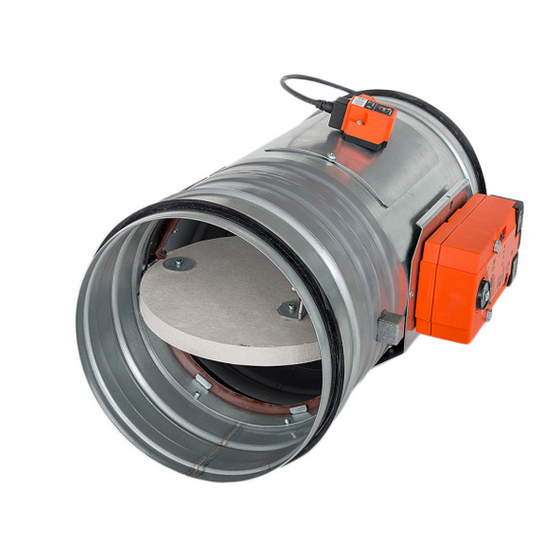
- Page 8 Limit switch „CLOSE“ Limit switch „CLOSE“ FDMB is always equipped by electric actuating mechanism BFL, BFN, BF 230-T or BFL, BFN, BF 230-T (further only "actuating mechanism"). After being connected to power supply AC/DC 24V or 230V, the actuating mechanism displaces the damper blade into operation position "OPEN"...
- Page 9 Actuating mechanism Actuating mechanism Caution: Power supply voltage! The actuator must be protected by a fuse that does not exceed 16 A. Parallel connection of other actuators possible. Observe the performance data. Combination of power supply voltage and safety extra-low voltage not permitted N L1 at the both auxiliary switches.
- Page 10 Nominal voltage AC 24 V 50/60 Hz AC 230 V 50/60 Hz DC 24 V Power consumption - motoring 3,5/5 W 2,5/4 W - holding 1,1/2,1 W 0,8/1,4 W Dimensioning 6,5/10 VA (Imax 4 A @ 5 ms) 4/6 VA (Imax 8,3 A @ 5 ms) Protection class Degree of protection IP 54...
- Page 11 Design .41 or .51 with actuating mechanism can be complemented with smoke detector MHG 231. The voltage can be AC 230 V or AC/DC 24 V. Design with voltage AC 230 V is equpped with Communication and supply device BKN 230-24-MA and with actuating mechanism BF 24-T (BFL 24-T, BFN 24-T).
- Page 12 Jumper BAE72B-S (BAT) Jumper BAE72B-S (BAT) Design with the communication and supply device BKN 230-24 and the actuating mechanism BF 24-T-ST (BFL 24-T, BFN 24-T). It simplifies electrical wiring and interconnection of fire flap valves. It facilitates on site check and enables central control and checks of fire damper by means of a simple 2-conductor wiring.
- Page 13 Actuating mechanism Actuating mechanism Nominal voltage AC 230 V 50/60Hz Power consumption 3,5 W (operating position) Dimensioning 11 VA (including actuating mechanism with spring return) Protection Class Degree of protection IP 42 Ambient temperature - 20 °C … + 50 °C Non-operating temperature - 40 °C …...
- Page 14 Design .61 with communication and supply device can be complemented with smoke detector MHG 231. For supply and comunnication is used BKN 230-24-MA. Jumper BAE72B-S (BAT) Design with the communication and supply device BKN 230-24MP and actuating mechanism BF24TL-T-ST for connection to MP-Bus. BKN 230-24MP supplies to intelligent actuating mechanisms of fire dampers BF 24TL-T-ST decentrally needed power supply.
- Page 15 Nominal voltage AC 24 V 50/60Hz DC 24 V Power consumption - motoring - holding Dimensioning 10 VA (Imax 8,3 A @ 5 ms) Protection class Degree of protection IP 54 Running time - motor 140 sec - spring return ~ 16 sec Ambient temperature - 20 °C …...
- Page 16 Nominal voltage AC 230 V 50/60Hz Power consumption 14 W (including actuating mechanism) Dimensioning 16 VA (including actuating mechanism) Protection Class Degree of protection IP 40 Ambient temperature - 30 °C … + 50 °C Non-operating temperature - 40 °C … + 80 °C Connection - net cable 1m, with Euro plug - actuator (BF…-Top)
-
Page 17: Description
Connection through an insulation transformer Control damper position switched on /off breakdown failure Reset Test damper position operation External buton optional 2-conductor wiring conection can open to BKN230-24 be interchanged Reset closed Test alarm Notice: Relay contacts are drawn without power light diodes contacts Description... - Page 18 BKS 24-9A communication and control device is used for group control and checks of 1 to 9 fire dampers with the actuating mechanism BF 24-T-ST (BFL 24-T-ST, BFN 24-T-ST) in connection with the supply and communication device BKN 230-24. Signalisation of the damper position is individual;...
- Page 19 Rectangular dampers Position: Damper body Damper blade Control lever Shutting spring Base plate Initiation lever Starting mechanism Pawl Thermal protective fuse 10 Inspection hole covering 11 Prestressing rosette 12 Terminal switch 13 Electromagnet (Solenoid) 14 Pulse switch SIEM24...
- Page 20 Position: Damper body Damper blade Control lever Shutting spring Base plate Initiation lever Starting mechanism Pawl Thermal protective fuse 10 Inspection hole covering 11 Prestressing rosette 12 Terminal switch 13 Electromagnet (Solenoid) 14 Pulse switch SIEM24 15 Control mechanism cover Damper body Damper blade 10 Inspection hole covering...
- Page 21 Damper body Shutting spring Starting mechanism Inspection hole covering Electromagnet (Solenoid) Damper blade Base plate Pawl Prestressing rosette Pulse switch SIEM24 Control lever Initiation lever Thermal protective fuse 12 Terminal switch Damper body 15 BAT thermoelectrical starting mechanism Damper blade 16 Actuating mechanism 10 Inspection hole covering...
- Page 22 Damper body Damper blade Control lever Shutting spring Base plate Initiation lever Starting mechanism Pawl Thermal protective fuse 10 Inspection hole covering 11 Rosette 12 Limit switch 13 Elektromagnet (solenoid) 14 Pulse swith SIEM24 15 Control mechanism cover Optional is possible use installation holders...
- Page 23 rectangular dampers - dimensions, weights and effective area 0,0113 97,5 0,0398 0,0137 - 117,5 9,0 10,5 0,0463 0,0161 11,0 0,0535 52,5 0,0191 10,0 13,0 0,0537 0,0222 10,5 13,5 0,0611 0,0258 11,5 14,5 0,0685 0,0282 11,5 14,5 0,0700 97,5 0,0300 12,0 15,0 0,0759 117,5...
- Page 24 13,0 16,0 0,1016 10,5 0,0308 13,5 16,5 0,1075 11,0 0,0363 13,5 16,5 0,1115 52,5 11,5 0,0432 14,5 17,5 0,1214 10,0 12,0 0,0501 14,5 17,5 0,1234 10,5 12,0 0,0584 15,0 18,0 0,1313 11,0 12,5 0,0639 15,5 18,5 0,1412 97,5 11,5 13,0 0,0680 17,0 20,0...
- Page 25 15 315 14,5 17,5 0,1437 21,0 24,0 0,2970 15,5 18,5 0,1611 40 340 22,0 25,0 0,3194 90 390 15,5 18,5 0,1646 24,0 27,0 0,3642 16,0 19,0 0,1785 140 440 25,5 28,5 0,4090 16,5 19,5 0,1890 10,0 13,0 0,0364 17,0 20,0 0,1959 10,5 13,5...
- Page 26 97,5 15 315 14,0 17,0 0,1249 24,5 27,5 0,3965 117,5 15,0 18,0 0,1469 11,5 14,5 0,0473 16,0 19,0 0,1715 12,0 15,0 0,0603 17,0 20,0 0,1989 12,5 15,5 0,0732 52,5 13,0 18,0 21,0 0,2263 16,0 0,0894 19,0 22,0 0,2537 13,5 16,5 0,1056 19,5 22,5...
- Page 27 24,0 27,0 0,3790 16,5 19,5 0,1382 24,5 27,5 0,3930 17,0 20,0 0,1637 12,5 15,5 0,0546 17,5 20,5 0,1806 97,5 18,0 13,0 16,0 0,0696 21,0 0,1933 - 117,5 19,5 13,5 16,5 0,0845 22,5 0,2273 52,5 14,5 17,5 0,1032 21,0 24,0 0,2654 15,0 18,0 0,1219...
- Page 28 Blades overlaps Act. mechanism side "a" Tab. 4.4.1 Side without act. mechanism "c" Tab. 4.4.1 Act. mechanism side "a" Tab. 4.5.1 Side without act. mechanism "c" Tab. 4.5.1 Side without act. mechanism "f" Tab. 4.5.1 For the design .60 (with BKN supply and communication device) add to weight of the damper with an actuating mechanism (from the Tab.
- Page 29 Fire dampers are suitable for installation in arbitrary position in vertical and horizontal passages of fire separating constructions. Damper assembly procedures must be done so as all load transfer from the fire separating constructions to the damper body is absolutely excluded. Back-to-back air-conditioning piping must be hung or supported so as all load transfer from the back-to-back piping to the damper is absolutely excluded.
- Page 30 BUILTIN EDGE - MINIMUM BUILTIN EDGE - MINIMUM BUILTIN EDGE - MAXIMUM BUILTIN EDGE - MAXIMUM The control mechanism has to be protected (covered) against damage and pollution during installation process. All fire dampers has to be closed during installation process. The damper body should not be deformed in the course of bricking in.
- Page 31 Installation opening dimensions For dampers with flanges is valid D + 160 mm ** The recommended dimension of the installation opening is from 40 mm to 80 mm on the both sides (it means from D+80 to D+160) *** The recommended dimension of the installation opening is from 25 mm to 50 mm on the both sides (it means from A+50 to A+100 or B+50 to B+100)
- Page 32 If is square damper installed outside a construction it is necessary to use reinforcement VRM-III. Statement of installations the fire dampers FDMB and their fire resistance Tab. 6.1.1. Mortar or gypsum Wet, battery...
- Page 33 Mortar or gypsum Wet, battery Mortar or gypsum Mortar or gypsum and mineral wool 70, 71 Wet, installation next to wall, ceiling Installation frame and mineral wool 71, 72 Stuffing box, fire protection mastic and cement lime plate stuffing box and fire protection mastic Installation frame E1, E2, R1, R2, R3, Weichschott Battery Installation frame...
- Page 34 ≥ 100 ≥ 50* * Around the perimeter ≥ 100 ≥ 40 POSITION: Fire damper FDMB Solid wall construction Mortar or gypsum Duct...
- Page 35 ≥ 30 ≥ 50 ≥ 40 ● Fire damper FDMB-C - installation opening for each damper has minimal dimensions a x b = (A+100) x (2xB +100) mm or (2xA+100) x (B +100) mm POSITION: ● Fire damper FDMB-K - installation opening for each damper has minimal dimensions...
- Page 36 POSITION: ● Wool is fixed to damper body and construction by fire protection mastic. Fire damper FDMB ● Mineral wool thickness = construction thickness + 20 mm or 50 mm Mortar or gypsum ● Installation is valid for ceiling construction...
- Page 37 POSITION: Fire damper FDMB ● Gap between frame and damper body and frame and Fire damper FDMB with installation frame R1, R2 construction must be filled by glue (PROMAT K84). Mortar or gypsum ● Wool is fixed to installation frame and construction by fire protection mastic.
- Page 38 D ≤ 400 400 < D ≤ 800 800 < D ≤ 1000 POSITION: Fire damper FDMB with installation frame R3, R4 Fire damper FDMB with installation frame R5 ● Wool is fixed to installation frame and construction by fire mineral stone wool min.
- Page 39 ≥ 50 ≥ 40 Used materials - example**: POSITION: Promapyr, Rockwool Steprock HD Fire damper FDMB Promastop - P, K Solid wall construction Promatect - H Stuffing box (mineral stone wool min. density 140 kg/m ) Fire protection mastic min. thickness 1 mm Fire resistant insulation and fire resistant board can Cement lime plate min.
-
Page 40: Installation Frames
≥ 100 ≥ 100 ≥ 100 ≥ 100 ≥ 100 ≥ 100 POSITION: Fire damper FDMB Installation frame Solid wall construction Installation details see chapter 7... - Page 41 2050 A+60 to 800 max. 1650 ≥ 100 D+60 to 800 max. 2050 POSITION: 1 Fire damper FDMB D+60 to 800 2 Solid wall construction max. 1650 3 Fire resistant board 4 Fire stop coating thickness 1 mm ≥ 100...
- Page 42 1260 < A1,D1 ≤ 1600 Solid wall construction construction must be filled by glue (PROMAT K84) ● Fire damper FDMB-C - distance between dampers 104 mm 1600 < A1 ≤ 2000 Mineral stone wool min. ● Fire damper FDMB-K - distance between dampers 160 mm density 140 kg/m ●...
- Page 43 Screws has to be fixed in wall/ceiling construction. (If it is needed use steel bracket). ≥ 50 ≥ 40 POSITION: L=Min. 100 L=Min. 400 Fire damper FDMB T=240 L=variable*** T=240 Solid wall construction T=180 ≥ 100 Stuffing box (mineral stone wool min. density 140 kg/m ) Fire protection mastic min.
- Page 44 ≥ 50* * Around the perimeter ≥ 100 ≥ 50 ≥ 100 POSITION: Fire damper FDMB Installation frame Solid wall construction Cement lime plate Duct Installation details see chapter 7...
- Page 45 Used materials - example**: 3 - Promapyr, Rockwool Steprock HD 4 - Promastop - P, K LEGENDA: Fire damper FDMB Fire resistant insulation and fire resistant board can Solid wall construction be replaced by another approved fire sealing Stuffing box (mineral stone wool min. density 140 kg/m ) system for damper installation with equivalent Fire protection mastic min.
- Page 46 150* ≥ 50** ** Around the perimeter 150* ≥ 40 * min. 110 - Concrete/ min. 125 - Aerated concrete POSITION: Fire damper FDMB Solid ceiling construction Mortar or gypsum Duct...
- Page 47 * min. 110 - Concrete/ min. 125 - Aerated concrete ** Around the perimeter ● Fire damper FDMB-C - installation opening for each damper has minimal dimensions a x b = (A+100) x (2xB +100) mm or (2xA+100) x (B +100) mm POSITION: ●...
- Page 48 150* * min. 110 - Concrete/ min. 125 - Aerated concrete POSITION: Used materials - example**: Fire damper FDMB Promapyr, Rockwool Steprock HD Solid ceiling construction Promastop - P, K Stuffing box (mineral stone wool min. density 140 kg/m ) Promatect - H Fire protection mastic min.
- Page 49 150* 150* 150* 150* 150* 150* * min. 110 - Concrete/ min. 125 - Aerated concrete POSITION: Fire damper FDMB Installation frame Solid ceiling construction Installation details see chapter 7...
- Page 50 2050 max. 1650 150* * min. 110 - Concrete/ min. 125 - Aerated concrete POSITION: 1 Fire damper FDMB 2 Solid ceiling construction 3 Fire resistant board 4 Fire stop coating thickness 1 mm 5 Duct Used materials - example**:...
- Page 51 Gap between frame and damper body and frame and construction 140 kg/m 1600 < A1 ≤ 2000 must be filled by glue (PROMAT K84) ● Fire damper FDMB-C - distance between dampers 104 mm 4 Flange connection ● Fire damper FDMB-K - distance between dampers 160 mm ●...
- Page 52 L=variable**** T=180 L=Min. 400 T=240 POSITION: Fire damper FDMB Solid ceiling construction Mortar or gypsum Stone wool bound with use of an organic resin with crushed stone as a refrigerant (min. density 300 kg/m ), EIS 90, thickness 60 mm Stone wool with one side stitched wire fencing (min.
- Page 53 ≤ 750 ≤ 750 150* 150* POSITION: Fire damper FDMB Solid ceiling construction ≤ 100 Concrete B20 Rebar * min. 110 - Concrete/ min. 125 - Aerated concrete ** Around the perimeter Duct ≤ 750 ≤ 750 150* 150* POSITION: * min.
- Page 54 ≥ 50** * min. 110 - Concrete/ min. 125 - Aerated concrete ** Around the perimeter 150* ≥ 50 150* POSITION: Fire damper FDMB Installation frame Solid ceiling construction Cement lime plate Duct Installation details see chapter 7...
- Page 55 Used materials - example***: 3 - Promapyr, Rockwool Steprock HD 4 - Promastop - P, K LEGENDA: Fire damper FDMB Solid ceiling construction *** Fire resistant insulation and fire resistant board can Stuffing box (mineral stone wool min. density 140 kg/m )
- Page 56 Installation opening has to be reinforced by profile (UW, CW). Profil is fixed by screws ≥3,5 mm with corresponding length. Distance between screws ≤200 mm. ≥ 40 POSITION: Fire damper FDMB Gypsum plate Fire resistant insulation Mortar or gypsum Duct...
- Page 57 ≥ 50 ≥ 40 POSITION: ● Fire damper FDMB-C - installation opening for each damper has minimal dimensions a x b = (A+100) x (2xB +100) mm or (2xA+100) x (B +100) mm Fire damper FDMB ● Fire damper FDMB-K - installation opening for each damper has minimal dimensions...
- Page 58 ● Wool is fixed to damper body and construction by fire protection POSITION: mastic Fire damper FDMB ● Mineral wool thickness = construction thickness + 20 mm or 50 mm ● Installation is valid for ceiling construction Mortar or gypsum Mineral stone wool min.
- Page 59 ● Gap between frame and damper body and frame and construction must be filled by glue (PROMAT K84). Fire damper FDMB with installation frame R1, R2 ● Wool is fixed to installation frame and construction by fire Mortar or gypsum protection mastic.
- Page 60 (UW, CW). Profil is fixed by screws ≥3,5 mm with corresponding length. Distance ≥ 10 ≥ 20 between screws ≤200 mm. ≥ 100 Fitting with threaded rods POSITION: Fire damper FDMB with installation frame R5 Fitting with threaded rods...
- Page 61 ≤200 mm. ≥ 50 ≥ 40 POSITION: Used materials - example**: Fire damper FDMB Gypsum plate 3 - Promapyr, Rockwool Steprock HD Fire resistant insulation 4 - Promastop - P, K Stuffing box (mineral stone wool min. density 140 kg/m ) 5 - Promatect - H Fire protection mastic min.
- Page 62 (UW, CW). Profil is fixed by screws ≥3,5 mm ≥ 100 ≥ 100 with corresponding length. Distance between screws ≤200 mm. POSITION: Fire damper FDMB Installation frame Gypsum plate Fire resistant insulation Installation details see chapter 7...
- Page 63 Profil is fixed by screws ≥3,5 mm with corresponding length. Distance between screws ≤200 mm. D+60 to 800 max. 2050 POSITION: 1 Fire damper FDMB D+60 to 800 2 Gypsum plate max. 1650 3 Fire resistant insulation 4 Fire resistant board ≥...
- Page 64 1260 < B1,D1 ≤ 1600 construction must be filled by glue (PROMAT K84) 1600 < B1 ≤ 2000 ● Fire damper FDMB-C - distance between dampers 104 mm Mineral stone wool min. ● Fire damper FDMB-K - distance between dampers 160 mm density 140 kg/m ●...
- Page 65 Distance between screws ≤200 mm. The screws must be firmly anchored in the profile of gypsum wall construction. ≥ 50 ≥ 40 POSITION: Fire damper FDMB Gypsum plate L=Min. 100 L=Min. 400 T=240 T=240 Fire resistant insulation L=variable*** Stuffing box (mineral stone wool min.
- Page 66 Used materials - example**: 3 - Promapyr, Rockwool Steprock HD 4 - Promastop - P, K LEGENDA: Fire damper FDMB Gypsum plate Fire resistant insulation and fire resistant board can Fire resistant insulation be replaced by another approved fire sealing system Stuffing box (mineral stone wool min.
- Page 67 ≥ 150 ≥ 150 ≥ 150 ≥ 150 POSITION: Fire damper FDMB Installation frame Solid ceiling construction Wall with possibility of ceiling movement Installation details see chapter 7...
- Page 68 Insert part A, B on body of fire damper in correct position Lock screw C It has to be done on each corner of VRM 1) Cut the groove for profil U25x40x25 2) Insert profile into groove 3) Fix profile 4) Fix second layer of insulation Screw 4,2x50 max.
- Page 69 Rectangular dampers Cement √ ≥100 √ ≥150 √ ≥100 lime Galvanized √ ≥100 √ ≥150 plate Cement √ ≥100 lime Cement Solid ceiling ≥100/ √ ≥100 √ *) ≥150 ≥150 √ lime construction *) ≥150 Cement √ **) ≥100 lime Cement ≥100/ √...
- Page 70 Round dampers Cement √ ≥100 √ ≥150 √ ≥100 lime Cement √ ≥150 √ ≥150 √ ≥100 lime Cement √ ≥100 √ ≥150 √ ≥100 lime Cement √ ≥150 √ ≥150 √ ≥100 lime Cement Solid ceiling ≥150 √ ≥100 lime construction *) Cement...
- Page 71 Installation frame can be delivered mounted on the damper body or separately.
- Page 72 A,B ≤ 400 400 < A,B ≤ 800 800 < A ≤ 1000 POSITION: Fire damper FDMB with installation frame E1 Holder with screws * min. 110 - Concrete/ min. 125 - Aerated concrete Gypsum plate Mineral stone wool min. density 140 kg/m...
- Page 73 ● a x b = (A + 100 mm) x (B + 100 mm) ≥ 100 >100 150* POSITION: Fire damper FDMB Installation frame E2 Mortar or gypsum Holder with bolt * min. 110 - Concrete/ min. 125 - Aerated concrete...
- Page 74 ≥ 50 POSITION: Number Number Dimensions Fire damper FDMB A,B ≤ 400 Installation frame E3 400 < A,B ≤ 800 Screw 800 < A ≤ 1000 Mineral stone wool min. density 140 kg/m Fire protection mastic min. thickness 1 mm...
- Page 75 ● a x b = (A + 100 mm) x (B + 100 mm) installation with concrete 150* max. 100 max. 750 * min. 110 - Concrete/ min. 125 - Aerated concrete 150* POSITION: Fire damper FDMB with installation frame E4 Fitting with threaded rods or steel bracket Concrete B20 Rebar...
- Page 76 ● For ceiling movement ≥10 mm Ceiling sag Ceiling sag B+85 B+85 POSITION: Fire damper FDMB with installation frame E5 Cement lime filling min. density 450 kg/m Ceiling movement: construction thickness 100 mm Extension part Suspension X = Ceiling movement (max. 40 mm) Fitting with threaded rods or steel bracket Y = Distance of movement (max.
- Page 77 Installation frame E6 is suitable for: ● Installation outside solid wall/ceiling construction with cement lime plates On the inside is installation frame equipped by intumescent sealing. It enlarges its capacity and air proofs the gap between installation frame and damper body. ●...
- Page 78 It is possible to use corresponding number of holes and screws 150* Number Number Dimensions D ≤ 400 400 < D ≤ 630 POSITION: * min. 110 - Concrete/ min. 125 - Aerated concrete Fire damper FDMB with installation frame R1 or R2 Holder...
- Page 79 It is possible to use corresponding number of holes and screws Number Number Dimensions 150* D ≤ 400 400 < D ≤ 630 POSITION: Fire damper FDMB with installation frame R3 or R2 * min. 110 - Concrete/ min. 125 - Aerated concrete Holder...
- Page 80 ● d = (D + 100 mm) installation with concrete 150* max. 100 max. 750 * min. 110 - Concrete min. 125 - Aerated concrete 150* POSITION: Fire damper FDMB with installation frame R5 Fitting with threaded rods or steel bracket Concrete B20 Rebar...
- Page 81 Installation frame R6 is suitable for: ● Installation outside solid wall/ceiling construction with cement lime plates On the inside is installation frame equipped by intumescent sealing. It enlarges its capacity and air proofs the gap between installation frame and damper body. ●...
- Page 82 Ceiling sag D+60 D+60 D+141 D+141 POSITION: Fire damper FDMB with installation frame R7 Cement lime filling min. density 450 kg/m Ceiling movement: construction thickness 100 mm Threaded rod Washer Ø 35 mm X = Ceiling movement (max. 40 mm) Fitting with threaded rods or steel bracket.
- Page 83 Shaft wall is a vertical, non-bearing partition construction meeting the double-sided fire requirements. The shaft wall can be mounted only from one side. No mineral insulation is used in the construction. First of all, the shaft wall structure must be laid out. Apart from other vertical constructions, the perimeter sections must be fitted with connection sealing made from A1 or A2 fire reaction materials (for instance floor strips Orsil N/PP).
- Page 84 (UW, CW). Profil is fixed by screws ≥3,5 mm with corresponding length. Distance between screws ≤200 mm. POSITION: Fire damper FDMB-S Used materials - example*: Mortar or gypsum Fire resistant board 3 - Glasroc F Ridurit tl. 20 mm...
- Page 85 Dimensions A,B ≤ 400 400 < A,B ≤ 800 800 < A ≤ 1000 POSITION: Fire damper FDMB-S Used materials - example*: Installation frame E1 4 - Glasroc F Ridurit tl. 20 mm Holder (including in installation frame E1 packing)
- Page 86 ≥ 100 ≥ 50 ≤ 250 ≤ 250 Installation opening has to be reinforced by profile (UW, CW). Profil is fixed by screws ≥3,5 mm with corresponding length. Distance between screws ≤200 mm. POSITION: Fire damper FDMA-R Used materials - example*: Mortar or gypsum Fire resistant board 3 - Glasroc F Ridurit tl.
- Page 87 Number Number Dimensions D ≤ 400 400 < D ≤ 630 POSITION: Fire damper FDMB-S Used materials - example*: Installation frame R1 Holder (including in installation frame R1 packing) 4 - Glasroc F Ridurit tl. 20 mm Fire resistant board...
- Page 88 ≥ 50 ≥ 40 ≥ 100 ≥ 50 ≥ 40 ≥ 100 POSITION: Fire damper FDMB Solid wall Fire resistant foam Stucco plaster Duct Used materials - example*: 3 - HILTI CFS-F FX - EIS 60 PROMAFOAM-C - EIS 45...
- Page 89 Profil je připevněn vruty ≥3,5 mm odpovídající délky ve vzdálenosti ≤200 mm. ≥ 50 ≥ 40 ≥ 100 POSITION: Fire damper FDMB Gypsum plate Fire resistant insulation Fire resistant foam Stucco plaster Used materials - example*: 3 - HILTI CFS-F FX - EIS 60...
- Page 90 ≥ 100 ≥ 40* * Around the perimeter ≥ 100 POSITION: Fire damper FDMB Solid wall Mortar or gypsum Stone wool with fire resistance EI 60, (min. density 66 kg/m ), thickness 80 mm Stone wool with fire resistance EI 60, (min. density 66 kg/m ),...
- Page 91 ≥ 40* * Around the perimeter ≥ 100 POSITION: Fire damper FDMB Solid wall Stuffing box (mineral stone wool min. density 140 kg/m ) Fire protection mastic min. thickness 1 mm Stone wool with fire resistance EI 60, (min. density 66 kg/m ), thickness 80 mm Stone wool with fire resistance EI 60, (min.
- Page 92 ≥ 50* ≥ 100 ≥ 40* * Around the perimeter ≥ 100 POSITION: Fire damper FDMB Gypsum plate Fire resistant insulation Mortar or gypsum Stone wool with fire resistance EI 60, (min. density 66 kg/m ), thickness 80 mm Stone wool with fire resistance EI 60, (min. density 66 kg/m ),...
- Page 93 ≥ 50* ≥ 40* * Around the perimeter ≥ 100 POSITION: Fire damper FDMB Gypsum plate Fire resistant insulation Stuffing box (mineral stone wool min. density 140 kg/m ) Fire protection mastic min. thickness 1 mm Stone wool with fire resistance EI 60, (min. density 66 kg/m ), thickness 80 mm Stone wool with fire resistance EI 60, (min.
-
Page 94: Suspension System
Mounting to the ceiling wall 36,6 Position: 58,0 Threaded rod M8 – M20 Washer Coupling Nut Anchor Hinge plate - min. thickness 10 mm Horizontal installation Fire dampers can be suspended by using threaded rods and a mounting profiles. Load the suspension system depend on weight of the fire damper. - Page 95 Fire damper Damping pad Extension piece Threaded rod Mounting rail U - Washer Washer Examples of using materials: Vertical installation Fire dampers can be suspended by using threaded rods and a mounting profiles. Load the suspension system depend on weight of the fire damper. Damper can be suspended from the ceiling construction or supported above the ceiling construc- tion.
- Page 96 Position: Fire damper Damping pad Extension piece Threaded rod Mounting rail U - Washer Washer Screw connection Mounting profile Mounting bracket Fire-resistant board The examples of using materials:...
- Page 97 Rectangular fire damper suspension on the wall - horizontal installation Duct between fire damper and fire separating construction can be suspended by using threaded rods and mounting profiles. Load the suspension system depend on weight of the fire damper and duct system. Max.
- Page 98 Horizontal installation Fire dampers can be suspended by using threaded rods and a mounting profiles. Load the suspension system depend on weight of the fire damper. Damper assembly procedures must be done so as all load transfer from the fire separating constructions to the damper body is absolutely excluded.
- Page 99 Damper must be firmly connected with extension piece by screws or rivets. Position: Fire damper Damping pad Extension piece Threaded rod Mounting rail Washer Screw connection Mounting profile Bolt Screw or rivet Expamples of using materials:...
- Page 100 Round fire damper suspension on the wall - horizontal installation Duct between fire damper and fire separating construction can be suspended by using threaded rods and suspension rings . Load the suspension system depend on weight of the fire damper and duct system.
-
Page 101: Pressure Loss
Pressure loss calculation [Pa] presure loss [m.s ] air flow speed in nominal damper section [kg.m ] air density coefficient of local pressure loss for the nominal damper section (see Tab. 13.1.1.) Determination of pressure loss by using diagram = 1,2 kg.m Coefficient of local pressure loss (-) - square dampers... - Page 102 4,771 3,458 2,717 2,285 1,813 1,538 1,407 1,327 1,165 1,040 2,025 1,874 4,102 3,251 2,351 2,016 1,676 1,342 1,221 1,136 0,986 0,922 1,676 1,548 3,701 2,951 2,105 1,867 1,554 1,302 1,113 1,052 0,933 0,801 1,445 1,332 3,654 2,873 2,056 1,726 1,475 1,226 1,067...
- Page 103 Coefficient of local pressure loss (-) - round dampers 1,812 1,380 1,110 0,892 0,747 0,627 0,531 0,455 0,393 0,344 0,307 0,273 0,243 Level of acoustic output corrected with filter A. + 10 log(S) + K [dB(A)] level of acoustic output corrected with filter A [dB] level of acoustic output L related to the 1 m section (see Tab.
- Page 104 11,5 14,7 16,9 20,1 22,3 24,1 27,2 29,4 31,2 32,6 33,8 16,7 22,1 25,3 27,5 30,7 32,9 34,6 37,8 40,0 41,7 43,2 44,4 24,2 29,6 32,8 35,0 38,1 40,4 42,1 45,3 47,5 49,2 50,7 51,9 30,0 35,4 38,6 40,8 44,0 46,2 47,9 51,1...
-
Page 105: Material
Damper bodies are supplied in the standard design made of galvanized plate without any other surface finish. Damper blades are made of fire resistant asbestos free boards made of mineral fibres. Damper controls are made of galvanized materials with no other surface finish. Springs are galvanized. - Page 106 Flange and screw joints must be conductively connected to protect against dangerous contact. 2 galvanized fan shape pads that are placed under the head of one screw and a fastened nut are used for conductive connection. To ensure reliable fire damper function it is necessary to avoid blocking the closing mechanism and contact surfaces with collected dust, fibre and sticky materials and solvents.
-
Page 107: Spare Parts
If fuses Tf2/Tf3 are initiated ( duct inside temperature ) than is possible change only part ZBAE72, or ZBAE95 (according initiating temperature). Data label is placed on the damper body. MANDÍK, a.s. Dobříšská 550 267 24 Hostomice Czech Republic FIRE DAMPER FDMB-S EI 90 (ve ho i o) S CLASSIFICATION: SIZE: DESIGN: SERIAL NUMBER:... - Page 108 Mortar or gypsum EIS 120 Mineral stone wool with mastic and EIS 90 cement lime plate Weichschott EIS 90 Mineral stone wool with mastic EIS 60 Installation frame E1 - square damper EIS 90 Installation frame E2 - square damper EIS 90 Installation frame R1 - round damper EIS 90...
- Page 109 EIS 90 54, 103, Mineral stone wool EIS 60 EIS 45 Installation frame R6 - round damper EIS 90 EIS 90 77, 105, Mineral stone wool EIS 60 EIS 45 Mortar or gypsum EIS 90 In concrete channel -installation frame EIS 90 E4 - square damper Installation frame E6 - square damper...
- Page 110 Dampers design Additional digit Manual and thermal Manual and thermal with a terminal switch ("CLOSED") Manual, thermal and with an electromagnet AC 230 V Manual, thermal and with an electromagnet AC 24 V Manual, thermal and with an electromagnet DC 24 V Manual, thermal and with an electromagnet AC 230 V, with a terminal switch ("CLOSED") Manual, thermal and with an electromagnet AC 24 V, with a terminal switch ("CLOSED") Manual, thermal and with an electromagnet DC 24 V, with a terminal switch ("CLOSED")
- Page 112 MANDÍK, a.s. Dobříšská 550 26724 Hostomice Czech Republic Tel.: +420 311 706 706 Fax: +420 311 584 810, 311 584 382 E-Mail: mandik@mandik.cz www.mandik.com The producer reserves the right for innovations of the product. For actual product information see www.mandik.com...
Need help?
Do you have a question about the FDMB and is the answer not in the manual?
Questions and answers