
Related Manuals for Mandik FDMD


Summary of Contents for Mandik FDMD
- Page 2 FIRE damper type FDMD, is in all variants classified: acc. EN 13501-3 and tested acc. EN 1366-2 and acc. EN 15650. Installation in a solid wall construction ≥ 100 ≥ 40 Fire damper FDMD Solid wall construction Mortar or gypsum...
- Page 3 Installation in a gypsum wall construction ≥ 100 Installation opening perimeter has to be reinforced by standard drywall profiles. ≥ 40 Fire damper FDMD Mortar or gypsum Fire protection plate of mineral wool Gypsum wall construction Duct Installation in a gypsum wall construction ≥...
- Page 4 Installation in a solid ceiling construction 150* Fire damper FDMD Solid ceiling construction Mortar or gypsum Duct * min. 110 - Concrete/ min. 125 - Aerated Concrete Installation in a solid ceiling construction ≥ 40 ≥ 50 Fire damper FDMD...
- Page 5 ≥ 100 ≥ 100 ≥ 100 Fire damper FDMD Installation frame Solid wall construction...
- Page 6 ≥ 100 ≥ 100 ≥ 100 Fire damper FDMD Installation frame Gypsum wall construction Fire protection plate of mineral wool...
- Page 7 150* 150* 150* Fire damper FDMD Installation frame Solid ceiling construction * min. 110 - Concrete/ min. 125 - Aerated Concrete...
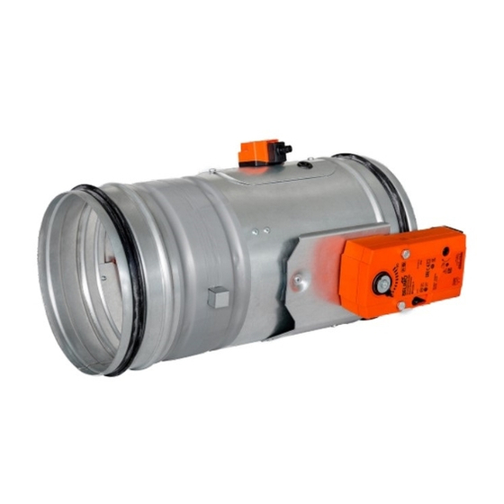
- Page 8 Damper casing Mechanics Damper blade Inspection hole covering Hole for camera Damper casing Actuating mechanism Damper blade Inspection hole covering BAT thermoelectrical starting mechanism Hole for camera...
- Page 9 1.) All fire dampers has to be closed during installation process. 2.) The control mechanism has to be protected (covered) against damage and pollution during installation process. 3.) Min. gap for installation (installation opening) is 25 mm (circular dimension D + 50 mm). Ø...
- Page 10 7.) Placement of the openings in the wall. Damper assembly procedures must be done so as all load transfer from the fire separating constructions to the damper body is absolutely excluded. Back-to-back air - conditioning piping must be hung or supported so as all load transfer from the back-to-back piping to the damper is absolutely excluded.
- Page 11 All fire dampers has to be closed during installation process. The damper body should not be deformed in the course of bricking in. Once the damper is built in, its blade should not grind on the damper body during opening or closing. 10.
- Page 12 14. Before entering the dampers with manual control into operation after their assembly and by sequential checks, checks according 13. and following checks must be carried out. Check of thermal protective fuse and closing mechanism. Push initiation lever lock "OPEN" to release the control lever and check its displacement into the position "CLOSED".
- Page 13 1. Damper bodies are supplied in the standard design made of galvanized plate without any other surface finish. 2. Damper blades are made of fire resistant asbestos free boards made of mineral fibres. 3. Damper controls are made of galvanized materials with no other surface finish. 4.
- Page 16 MANDÍK, a.s. Dobříšská 550 26724 Hostomice Czech Republic Tel.: +420 311 706 706 e-mail: mandik@mandik.cz www.mandik.com...
Need help?
Do you have a question about the FDMD and is the answer not in the manual?
Questions and answers