Mandik FDMB Installation And Operation Manual
Fire damper
Hide thumbs
Also See for FDMB:
- Manual (112 pages) ,
- Technical documentation manual (49 pages) ,
- Installation instructions manual (32 pages)
Table of Contents
Advertisement
Quick Links
TPM 164/22
Version 2024-07-01
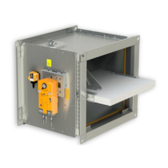
FDMB
Fire damper
Technical Documentation
Installation, Commissioning, Operation, Maintenance and Service Manual
www.mandik.co.uk
Manufacturer
MANDÍK, a. s. • Dobříšská 550 • 267 24 Hostomice • Czech Republic • Tel.: +420 311 706 742 • E-Mail: mandik@mandik.cz
Authorized representative
MANDIK UK Ltd • 130 Aztec West • Bristol BS32 4UB • United Kingdom • Tel.: +44 117 4526376 • E-Mail: help@mandik.co.uk
Advertisement
Table of Contents

Related Manuals for Mandik FDMB


Summary of Contents for Mandik FDMB
- Page 1 Manufacturer MANDÍK, a. s. • Dobříšská 550 • 267 24 Hostomice • Czech Republic • Tel.: +420 311 706 742 • E-Mail: mandik@mandik.cz Authorized representative MANDIK UK Ltd • 130 Aztec West • Bristol BS32 4UB • United Kingdom • Tel.: +44 117 4526376 • E-Mail: help@mandik.co.uk...
-
Page 2: Table Of Contents
TPM 164/22 These technical specifications state a row of manufactured sizes and models of fire dampers FDMB. It is valid for production, designing, ordering, delivery, maintenance and operation. CONTENT I. GENERAL.....................................3 Description....................................3 II. DESIGN.......................................4 Design with manual control..............................4 Design with spring return actuator............................6 Communication and control module MDCM........................11... -
Page 3: General
FDMB with spring return actuator FDMB with manual control Damper characteristics CE certified acc. to BS EN 15650 ■... -
Page 4: Design
"CLOSED" and "OPEN". Limit switch detail → see page 5 ■ Limit switch Limit switch “OPEN” “CLOSED” Design .80 Page 4 Fire damper - FDMB Version 2024-07-01... - Page 5 Class of protection IP 67 CUT-OFF if the arm is moving … connect wire 1+2 ■ Working temperature -25°C … +120°C SWITCH-ON if the arm is moving … connect wire 1+4 ■ Version 2024-07-01 Fire damper - FDMB Page 5...
-
Page 6: Design With Spring Return Actuator
"CLOSED". The time of closing the damper blade from the position ■ "OPEN" to the position "CLOSED" takes maximum 20 sec. Thermoelectric activation device BAT Spring return actuator Design .40 and .50 Page 6 Fire damper - FDMB Version 2024-07-01... - Page 7 1 m, 2 x 0,75 mm² (BFL 2xx-T-ST) with 3-pin plug-in connectors - auxiliary switch cable 1 m, 6 x 0,75 mm² (BFL 2xx-T-ST) with 6-pin plug-in connectors duct outside temperature +72°C Response temperature thermal fuse duct inside temperature +72°C Version 2024-07-01 Fire damper - FDMB Page 7...
- Page 8 1 m, 2 x 0,75 mm² (BFN 2xx-T-ST) with 3-pin plug-in connectors - auxiliary switch cable 1 m, 6 x 0,75 mm² (BFN 2xx-T-ST) with 6-pin plug-in connectors duct outside temperature +72°C Response temperature thermal fuse duct inside temperature +72°C Page 8 Fire damper - FDMB Version 2024-07-01...
- Page 9 1 m, 2 x 0,75 mm² (BF 2xx-TN-ST) with 3-pin plug-in connectors - auxiliary switch cable 1 m, 6 x 0,75 mm² (BF 2xx-TN-ST) with 6-pin plug-in connectors duct outside temperature +72°C Response temperature thermal fuse duct inside temperature +72°C Version 2024-07-01 Fire damper - FDMB Page 9...
- Page 10 Ambient humidity Max. 95% RH, non-condensing Connection supply Cable 1 m, 2 x 0.5 mm², Betaflam cable heatresistant up to 145°C Duct inside temperature +72°C Response temperature thermal fuse Duct outside temperature +72°C Page 10 Fire damper - FDMB Version 2024-07-01...
-
Page 11: Communication And Control Module Mdcm
FCC. This accessory is only required with MANDIK control systems. ■ Each MDCM has a 230v local spur to power the damper actuator. ■... -
Page 12: Dimensions
* X=23 (AxB≤500x400) * X=36 (AxB>500x400) Damper casing Manual control Damper blade Inspection opening cover Sensor sticker Hole for camera FDMB with spring return actuator (60+X)/2 B-X* B+60 B+60 * X=14 (A<160 or B<160) Y=72 mm (BFL) * X=23 (AxB≤500x400) Y=76 mm (BFN) * X=36 (AxB>500x400) - Page 13 X=14 (A<160 or B<160) 16,5 X=23 (AxB≤500x400) Values "a" and "c" has to be respected when projecting X=36 (AxB>500x400) related air-conditioning ducts. 30 mm wide flanges are fitted with oval holes in the corners Version 2024-07-01 Fire damper - FDMB Page 13...
-
Page 14: Technical Parameters
150 x 0,0112 11,9 12,0 0,0605 0,0124 12,4 12,5 0,0657 0,0149 12,7 12,8 0,0695 0,0173 12,9 13,0 0,0721 0,0204 13,5 13,9 0,0785 Sizes listed within the maximum/minimum sizes can be manufactured on request. Page 14 Fire damper - FDMB Version 2024-07-01... - Page 15 13,8 14,2 0,1170 13,7 14,1 0,0939 14,4 14,8 0,1238 13,9 14,3 0,0974 14,8 15,2 0,1284 14,5 14,9 0,1060 15,1 15,5 0,1398 Sizes listed within the maximum/minimum sizes can be manufactured on request. Version 2024-07-01 Fire damper - FDMB Page 15...
- Page 16 16,9 17,3 0,1785 15,6 16,0 0,1428 17,4 17,8 0,1890 15,9 16,3 0,1481 17,7 18,1 0,1959 16,6 17,0 0,1612 18,5 18,9 0,2133 Sizes listed within the maximum/minimum sizes can be manufactured on request. Page 16 Fire damper - FDMB Version 2024-07-01...
- Page 17 0,0400 600 x 21,8 23,9 0,2970 11,7 11,8 0,0510 22,7 24,8 0,3194 12,1 12,2 0,0619 24,6 26,7 0,3642 12,6 12,7 0,0756 Sizes listed within the maximum/minimum sizes can be manufactured on request. Version 2024-07-01 Fire damper - FDMB Page 17...
- Page 18 16,9 17,0 0,1591 20,9 21,3 0,2769 18,3 18,7 0,1871 21,1 23,2 0,2829 19,4 19,8 0,2185 22,0 24,1 0,3068 20,6 21,0 0,2534 Sizes listed within the maximum/minimum sizes can be manufactured on request. Page 18 Fire damper - FDMB Version 2024-07-01...
- Page 19 0,3538 23,4 23,8 0,2967 25,1 27,2 0,3837 24,9 25,3 0,3441 14,5 14,6 0,0619 26,4 28,5 0,3915 900 x 15,1 15,2 0,0789 Sizes listed within the maximum/minimum sizes can be manufactured on request. Version 2024-07-01 Fire damper - FDMB Page 19...
-
Page 20: Installation
No other services should pass through the dampers building work opening. ■ For lightweight walls always consult the wall manufacturer specific guidelines for penetrations sizes and distances. ■ Page 20 Fire damper - FDMB Version 2024-07-01... - Page 21 100 mm. Outside the wall/ceiling contruction. The duct and ■ damper must be protected by fire insulation. Gypsum wall construction with min. thickness 100 mm ■ Version 2024-07-01 Fire damper - FDMB Page 21...
-
Page 22: Statement Of Installations
EI 90 (v o) S ↔ In shaft wall construction Ablative Coated Batt EI 60 (v o) S ↔ EI 120 (h o) S In solid ceiling construction Mortar or gypsum ↔ Page 22 Fire damper - FDMB Version 2024-07-01... -
Page 23: In Solid Wall Construction
≥ 100 FDMB Solid wall construction British gypsum thistle bond 60 (or equivalent can by used) minimum density 670 kg/m³ Fixing profile with threaded rod → see pages 32 to 33 Duct Version 2024-07-01 Fire damper - FDMB Page 23... - Page 24 Fire resistant mastic - fill the gap on both sides of the fire separation construction and around the perimeter of penetration and damper body. (e.g. HILTI CFS-S ACR) Fixing profile with threaded rod → see pages 32 to 33 Page 24 Fire damper - FDMB Version 2024-07-01...
-
Page 25: Installation Outside Solid Wall Construction
ISOVER Protect BSF body. (e.g. HILTI CFS-S ACR) Fixing profile with threaded rod → see pages 32 to 33 VRM2-B → see page 42 Version 2024-07-01 Fire damper - FDMB Page 25... -
Page 26: In Gypsum Wall Construction
≥ 100 FDMB Gypsum wall construction British gypsum thistle bond 60 (or equivalent can by used) minimum density 670 kg/m³ Fixing profile with threaded rod → see pages 32 to 33 Duct Page 26 Fire damper - FDMB Version 2024-07-01... - Page 27 Fire resistant mastic - fill the gap on both sides of the fire separation construction and around the perimeter of penetration and damper body. (e.g. HILTI CFS-S ACR) Fixing profile with threaded rod → see pages 32 to 33 Version 2024-07-01 Fire damper - FDMB Page 27...
- Page 28 Fire resistant mastic - fill the gap on both sides of the fire separation construction and around the perimeter of penetration and damper body. (e.g. HILTI CFS-S ACR) Fixing profile with threaded rod → see pages 32 to 33 Page 28 Fire damper - FDMB Version 2024-07-01...
-
Page 29: Installation Outside Gypsum Wall Construction
ISOVER Protect BSF body. (e.g. HILTI CFS-S ACR) Fixing profile with threaded rod → see pages 32 to 33 VRM2-B → see page 42 Version 2024-07-01 Fire damper - FDMB Page 29... -
Page 30: In Shaft Wall Construction
Fire stop coating - th. 1 mm (HILTI CFS-CT...) - coating is overcoated on the support construction and on the damper casing/duct 10 Firestop acrylic sealant - (HILTI CFS-S ACR...) fill the gap from both sides of the fire separation construction and around the perimeter of penetration and damper casing Page 30 Fire damper - FDMB Version 2024-07-01... -
Page 31: In Solid Ceiling Construction
FDMB Solid ceiling construction British gypsum thistle bond 60 (or equivalent can by used) minimum density 670 kg/m³ Fixing profile with threaded rod → see pages 32 to 33 Duct Version 2024-07-01 Fire damper - FDMB Page 31... -
Page 32: Suspension Systems
Washer for M8 - M20 Coupling Nut M8 - M20 84,3 Anchor Hinge plate - min. thickness 10 mm Concrete screw tested for fire resistance R30-R90, max. Tension up to 0.75 KN (length 35 mm) Page 32 Fire damper - FDMB Version 2024-07-01... - Page 33 Example of placing of mounting profiles HILTI max. 50 FDMB Threaded rod M8 - M12 Support HILTI MQ-41 or MQ-41/3 Bored plate HILTI MQZ-L Washer for M8 - M12 Nut M8 - M12 Version 2024-07-01 Fire damper - FDMB Page 33...
-
Page 34: Example Of Duct Connection
TPM 164/22 Example of duct connection FDMB Connecting air duct Extension piece (if required) Damping pad or breakaway connection as DW 144 Page 34 Fire damper - FDMB Version 2024-07-01... -
Page 35: Technical Data
ρ [kg/m air density ξ coefficient of local pressure loss for the nominal damper section → see page 36 Determination of pressure loss by using diagram ρ = 1,2 kg/m Version 2024-07-01 Fire damper - FDMB Page 35... - Page 36 – – – 0,602 0,528 0,474 0,434 – – – – – – – – – – 1000 0,585 0,512 0,460 – – – – – – – – – – – Page 36 Fire damper - FDMB Version 2024-07-01...
-
Page 37: Noise Data
-16,7 -24,1 -33,2 -5,2 -3,9 -4,3 -6,4 -10,1 -15,6 -22,7 -31,5 -5,5 -4,1 -5,9 -9,4 -14,6 -21,5 -5,9 -4,1 -5,6 -8,9 -13,8 -20,4 -28,8 -6,2 -4,3 -3,9 -5,3 -8,4 -13,1 -19,5 -27,6 Version 2024-07-01 Fire damper - FDMB Page 37... -
Page 38: Material, Finishing
The damper blade in the variant for chemical environments (Class A4) is always treated with a coating of chemically resistant Promat SR. Any other requirements for the design will be considered atypical and will be addressed on an individual basis. Page 38 Fire damper - FDMB Version 2024-07-01... -
Page 39: Transportation And Storage
BAT. To restore correct locked. Unlocking is possible even manually as per damper operation, the actuator must be unlocked (manually or by applying power supply). Version 2024-07-01 Fire damper - FDMB Page 39... - Page 40 Protection of the damper casing against buckling during installation, especially for large sizes! WRONG! Reinforcement of the casing with wooden beams Page 40 Fire damper - FDMB Version 2024-07-01...
- Page 41 Change of manual control for the actuator or vice versa Damper Thermal fuse Mouting plate Manual control Sealing cover Spring return actuator Sealing of a mouting plate Thermoelectric activation device BAT Cover of a mouting plate 10 Sensor sticker Version 2024-07-01 Fire damper - FDMB Page 41...
- Page 42 M8x50 hexagon socket bolts DIN 912 + four M8 washers DIN 7349. FDMB VRM2-B Part A of VRM2-B Part B of VRM2-B Hexagon socket bolt M8x50 DIN 912 Washer M8/8,4 DIN 7349 Glue PROMAT K-84 Page 42 Fire damper - FDMB Version 2024-07-01...
- Page 43 (SUPALUX, thickness 9 or 15 mm can be used as an alternative) Can be ordered from MANDIK (installed on the damper or ■ as an accessory) or can be sourced from local supplier Glue K84 is not included in the package ■...
-
Page 44: Entry Into Service And Revisions
Removing the thermal fuse from the fuse holder of a manual control, checks its correct functionality. ■ The manual control is identified as M1 to M3, depending on the closing spring strength. ■ Page 44 Fire damper - FDMB Version 2024-07-01... - Page 45 If the thermal fuse Tf2 is interrupted (due to temperature inside the duct) , only the spare part ZBAT 72 (95/120/140) needs ■ to be replaced (acc.to the activation temperature). → see page 10 Version 2024-07-01 Fire damper - FDMB Page 45...
-
Page 46: Ordering Informations
A - with protective cladding boards (for Ablative Coated Batt installation) design building length of a damper size AxB EXAMPLE: FDMB 800x400/375 .40 A - 800x400-damper size, /375-building length of a damper, .40-damper design, A - with protective cladding boards Dampers design Additional digit Manual control and thermal Manual control and thermal with a terminal switch („CLOSED“) -
Page 47: Data Label
Cert. No.: 2822-UKCA-CPR-XXXX, DoP: PM/XXXX/XX/XX/X EN 15650:2010 MANDÍK, a.s. Dobříšská 550, 267 24 Hostomice, Czech Republic DIMENSION: DESIGN: WEIGHT (kg): SERIAL.NO.: MANUAL CLASSIFICATION: TPM XXX/XX Cert. No.: 1391-CPR-XXXX/XXXX, DoP: PM/XXXX/XX/XX/X EN 15650:2010 Version 2024-07-01 Fire damper - FDMB Page 47... - Page 48 Manufacturer MANDÍK, a. s. • Dobříšská 550 • 267 24 Hostomice • Czech Republic • Tel.: +420 311 706 742 • E-Mail: mandik@mandik.cz Authorized representative MANDIK UK Ltd • 130 Aztec West • Bristol BS32 4UB • United Kingdom • Tel.: +44 117 4526376 • E-Mail: help@mandik.co.uk...
Need help?
Do you have a question about the FDMB and is the answer not in the manual?
Questions and answers