Mandik FDMR 60 Manual
Hide thumbs
Also See for FDMR 60:
- Technical documentation manual (47 pages) ,
- Installation instructions manual (11 pages) ,
- Manual (29 pages)
Table of Contents
Advertisement
Quick Links
Advertisement
Table of Contents

Related Manuals for Mandik FDMR 60


Summary of Contents for Mandik FDMR 60
-
Page 2: Table Of Contents
These Technical Specifications define the range of the manufactured sizes and models, the main dimensions and the scope of use of the FDMR 60 fire dampers (hereinafter referred to only as the "fire dampers"). They are binding for production, designing, ordering, delivery, storage, assembly, operation, maintenance and operability inspections. - Page 3 Fire dampers are shutters in ducts of air-conditioning devices that prevent spreading the fire and combustion products from one fire segment to the other one by means of closing the duct in the points of fire separating constructions. The damper blade automatically closes the air duct using a shutting spring or an actuating mechanism of back spring.
- Page 4 Design with mechanical control Design with mechanical control with a thermal protective fuse which actuates the shutting device, after the nominal start temperature 72°C has been reached. Automatic initiation of the shutting device is not activated if the temperature does not exceed 70°C. In case that other start temperatures are required, thermal fuses with nominal start temperature +104°C or +147°C can be supplied (this requirement must be specified in the order).
- Page 5 1(COM) - black wire 2(NC) - gray wire 4(NO) - blue wire AC 230V / 5A This limit switch is possible to connect in following two versions: IP 67 if the arm is moving … connect wire 1+2 -25°C … +120°C if the arm is moving …...
- Page 6 N L1 S1 S2 <5° <80° S1 S2 <5° <80° AC 24 V 50/60 Hz Nominal voltage AC 230 V 50/60 Hz DC 24 V Power consumption - motoring 3,5/5 W 2,5/4 W - holding 1,1/2,1 W 0,8/1,4 W Dimensioning 6,5/10 VA (Imax 4 A @ 5 ms) 4/6 VA (Imax 8,3 A @ 5 ms) Protection class...
- Page 7 Design with the communication and supply device BKN 230-24 and the actuating mechanism BFL 24-T. It simplifies electrical wiring and interconnection of fire flap valves. It facilitates on site check and enables central control and checks of fire damper by means of a simple 2-conductor wiring.
- Page 8 Nominal voltage AC 230 V 50/60Hz Power consumption 3,5 W (operating position) Dimensioning 11 VA (including actuating mechanism with spring return) Protection Class Degree of protection IP 40 Ambient temperature -20°C … +50°C Non-operating temperature -40°C … +80°C Connection - net cable 0,9 m with EURO plug type 26 - motor 6-pole connector, 3-pole connector...
-
Page 9: Description
BKS 24-1B communication and control device is used for control and checks of fire dampers with the BFL 24-T-ST actuating mechanism in conjunction with the BKN 230-24 supply and communication device. BKS 24-1B receives information about the situation of the fire damper through the BKN 230-24 supply and communication device and issues controlling commands. - Page 10 Nominal voltage AC 24 V 50/60Hz Power consumption 2,5 W (operating position) Dimensioning 5 VA Protection Class Degree of protection IP 30 Ambient temperature 0 … +50°C 11-pole connector ZSO-11, it is not part of BKS24-1B, Connection ZSO-11 is 11-pole screw terminal 11 x 1,5 mm² BKS 24-9A communication and control device is used for group control and checks of 1 to 9 fire dampers with the actuating mechanism BFL 24-T-ST in connection with the supply and communication device BKN 230-24.
- Page 11 Nominal voltage AC 24 V 50/60Hz Power consumption 3,5 W Dimensioning 5,5 VA Protection Class Degree of protection IP 30 Ambient temperature 0 … +50°C Connection terminal 2 x 1,5 mm²...
-
Page 12: Dimensions, Weights And Effective Area
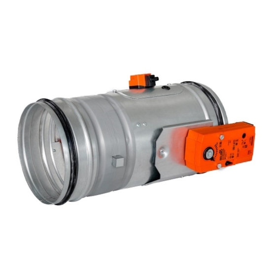
Dimensions, weights and effective area 0,0031 0,0062 0,0085 0,0103 0,0123 0,0166 0,0215 0,0275 0,0354 0,0462 40,5 0,0606 60,4 0,0776 0,1015... - Page 13 Position: Damper casing Mechanic Damper blade Inspection hole covering Sensor sticker Hole for camera Position: Damper casing Actuating mechanism Damper blade Inspection hole covering BAT thermoelectrical starting mechanism Hole for camera...
- Page 14 Blades overlaps Side without act. mechanism "a" Tab. 4.1.1 For the design .60 (with BKN supply and communication device) add to weight of the damper with an actuating mechanism (from the Tab 4.4.1.) the weight of BKN (0.5 kg).
- Page 15 200 mm at the minimum, according to EN 1366-2 paragraph 13.5. For admissible exceptions see Section 6. Distance between dampers 200 mm is acc. to EN 1366-2. FDMR 60 has option to by installed one next to each other, so called "in assembly" installation. Built in edge "Wall edge sticker"...
- Page 16 Examples of fire damper installing The fire damper can be integrated into a solid wall construction made e.g. of normal concrete/ masonry, porous concrete with minimum thickness 100 mm or into solid ceiling construction made e.g. of normal concrete with minimum thickness 110 mm or porous concrete with minimum thickness 125 mm.
- Page 17 Mortar or gypsum Stuffing box and fire protection mastic Installation next to wall - mortar or gypsum and mineral wool Mineral wool - stuffing box and fire protection mastic - ISOVER_ULTIMATE PROTECT Mortar or gypsum Stuffing box and fire protection mastic Installation next to wall - mortar or gypsum and mineral wool Mineral wool - stuffing box and fire protection...
- Page 18 ≥ 40 ≥ 100 Position: Fire damper Solid wall construction Mortar or gypsum Duct ≥ 100 ≥ 50 ≥ 25 Used materials - example:* 3 Promapyr, Rockwool Steprock HD, Hilti CFS-CT B 1S 140/50 Position: 4 Promastop - P, K, Hilti CFS-CT Fire damper * Fire resistant insulation and fire resistant board can be Solid wall construction...
- Page 19 ≥ 10* ≥ 100 (≥ 100)+50 ≥ 10* ≥ 100 Gap between damper and construction is filled ● by mortar or gypsum and mineral wool Position: ● Wool is fixed to damper body and construction Fire damper by fire protection mastic. ●...
- Page 20 ≥ 40* ≥ 25* * Around the perimeter ≥ 100 Used materials - example:** Position: Promapyr, Rockwool Steprock HD, Hilti CFS-CT B 1S 140/50 Fire damper Promastop - P, K, Hilti CFS-CT Solid wall construction System ISOVER_ULTIMATE PROTECT, th. 100 mm Stuffing box (mineral stone wool min.
- Page 21 Installation opening has to be reinforced by profile (UW, CW). Profil is fixed by screws ≥3,5 mm with corre- sponding length. Distance between screws ≤200 mm. ≥ 40 Position: ≥ 100 Fire damper Gypsum plate Mineral wool (type depending on the type of construction) Mortar or gypsum Duct ≥...
- Page 22 D-20 Installation opening has to be reinforced by profile (UW, CW). Profil is fixed by screws ≥3,5 mm with corre- ≥ 10 sponding length. Distance between screws ≤200 mm. ≥ 100 (≥ 100)+50 Installation opening has to be reinforced by profile (UW, CW).
- Page 23 Installation opening has to be reinforced by profile (UW, CW). Profil is fixed by screws ≥3,5 mm with corre- sponding length. Distance between screws ≤200 mm. ≥ 40* ≥ 25* * Around the perimeter ≥ 100 Position: Fire damper Used materials - example:** Gypsum plate Promapyr, Rockwool Steprock HD, Hilti CFS-CT B 1S 140/50 Mineral wool...
- Page 24 ≥ 40 Position: Fire damper Solid ceiling construction * min. 110 - Concrete/ min. 125 - Aerated concrete Mortar or gypsum Duct ≥ 25 ≥ 50 * min. 110 - Concrete/ min. 125 - Aerated concrete Used materials - example:** 3 Promapyr, Rockwool Steprock HD, Hilti CFS-CT B 1S 140/50 Position: 4 Promastop - P, K, Hilti CFS-CT...
- Page 25 ≥ 40 ≥100 variable*** variable*** ≥ 40 * min. 110 - Concrete/ min. 125 - Aerated concrete Used materials - example:** System ISOVER_ULTIMATE PROTECT, th. 100 mm Position: Fire damper Stuffing box, fire protection mastic, cement lime plate and insulation materials can be replaced by another approved fire sealing system for damper installation with Solid ceiling construction equivalent material properties.
- Page 26 ≥ 100 Position: Used materials - example:* Fire damper Paroc AST S th. 100 mm Sandwich wall construction Promapyr, Rockwool Steprock HD, Hilti CFS-CT B 1S 140/50 Stuffing box (mineral stone wool Promastop - P, K, Hilti CFS-CT min. density 140 kg/m³ HILTI CFS-S ACR Fire protection coating th.
- Page 27 ≥ 100 Position: Used materials - example:* Fire damper Paroc AST S th. 100 mm Sandwich wall construction Promapyr, Rockwool Steprock HD, Hilti CFS-CT B 1S 140/50 Stuffing box (mineral stone wool min. density 140 kg/m³) Promastop - P, K, Hilti CFS-CT Fire protection coating th.
- Page 28 ≥ 100 Position: Fire damper Solid shaft construction Mortar or gypsum Duct...
- Page 29 Used materials - example:* Position: 2x RF 15 mm / CW 75, insulation 50 mm - 40 kg/m³ Fire damper Promapyr, Rockwool Steprock HD, Hilti CFS-CT B 1S 140/50 Promastop - P, K, Hilti CFS-CT Gypsum shaft construction * Fire resistant insulation and fire resistant board can be Mineral wool (type depending on the type of construction) replaced by another approved fire sealing system for Stuffing box (mineral stone wool min.
- Page 30 Mounting to the ceiling wall ² Position: Threaded rod M8 – M20 84,3 Washer Coupling Nut Anchor Hinge plate - min. thickness 10 mm...
- Page 31 Connection of air ductwork to the wall with fire filler (stone wool + mastic) Position: Solid wall construction Gypsum wall construction Fire damper Spiral pipe Stuffing box (stone wool+mastic) Hanging ring for hanging round pipes Threaded rod with anchor for anchoring connecting pipe to the ceiling Fixing element/steel holder for connecting pipe to the wall (recommended type)
- Page 32 Connection of connecting air ductwork to the ceiling with fire filler (stone wool + mastic) Position: Solid ceiling construction Fire damper Spiral pipe Stuffing box (stone wool+mastic) Hanging ring for hanging round pipes Threaded rod with anchor for anchoring connecting pipe to the wall Fixing element/steel holder for connecting pipe to the ceiling (recommended type) Nut M8 with anchor...
- Page 33 Connection of air ductwork when remote from the wall with fire filler (stone wool + mastic) Position: Solid wall construction Gypsum wall construction Fire damper Spiral pipe Stuffing box (stone wool+mastic) Hanging ring for hanging round pipes Threaded rod with anchor for anchoring connecting pipe to the ceiling Fixing element/steel holder for connecting pipe to the wall (recommended type)
- Page 34 Connection of downstream air ductwork when remote from the ceiling with fire filler (stone wool + mastic) Position: Solid ceiling construction Fire damper Spiral pipe Stuffing box (stone wool+mastic) Hanging ring for hanging round pipes Threaded rod with anchor for anchoring connecting pipe to the wall Fixing element/steel holder for connecting pipe to the ceiling (recommended type)
-
Page 35: Suspension System
Fire dampers can be suspended by using threaded rods and a mounting profiles. Load the suspension system depend on weight of the fire damper. Damper assembly procedures must be done so as all load transfer from the fire separating constructions to the damper body is absolutely excluded. Back-to-back air-conditioning piping must be hung or supported so as all load transfer from the back-to-back piping to the damper is absolutely excluded. - Page 36 Damper must be firmly connected with extension piece by screws or rivets. Position: Fire damper Damping pad Extension piece Threaded rod Mounting rail Washer Screw connection Mounting profile 10 Bolt Examples of using materials: 11 Screw or rivet...
- Page 37 Duct between fire damper and fire separating construction can be suspended by using threaded rods and suspension rings . Load the suspension system depend on weight of the fire damper and duct system. Max. length between two suspension systems is 1500 mm. Damper assembly procedures must be done so as all load transfer from the fire separating constructions to the damper body is absolutely excluded.
-
Page 38: Pressure Loss
Pressure loss calculation [Pa] presure loss [m.s ] air flow speed in nominal damper section [kg.m ] air density coefficient of local pressure loss for the nominal damper section (see Tab. 9.1.1.) Determination of pressure loss by using diagram = 1,2 kg.m... -
Page 39: Coefficient Of Local Pressure Loss
Coefficient of local pressure loss 2,736 2,099 1,781 1,527 1,272 0,929 0,636 0,892 0,747 0,627 0,531 0,455 0,393 0,344 0,307 0,273 0,243 0,111 0,099 Level of acoustic output corrected with filter A. + 10 log(S) + K [dB(A)] level of acoustic output corrected with filter A. [dB] level of acoustic output L related to the 1 m²... - Page 40 Table of acoustics values 11,5 14,7 16,9 20,1 22,3 24,1 27,2 29,4 31,2 32,6 33,8 16,7 22,1 25,3 27,5 30,7 32,9 34,6 37,8 41,7 43,2 44,4 24,2 29,6 32,8 38,1 40,4 42,1 45,3 47,5 49,2 50,7 51,9 30,0 35,4 38,6 40,8 46,2 47,9...
-
Page 41: Material
Damper bodies are supplied in the design made of galvanized plate without any other surface finishing. Damper blades are made of fire resistant asbestos free boards made of mineral fibres. Control devices of dampers has cover from mechanically resistant and standing plastic and rest of the parts is galvanised without further surface treatment. - Page 42 Sizes are checked by common measuring instruments according to the standard of non-tolerated sizes, used in air conditioning industry. Interoperational checks of components and main sizes are carried out according to drawing documentation. After workshop installation, a 100% check of function of closing mechanism and electric compo- nents is carried out.
- Page 43 The assembly of the dampers must be carried out while observing all applicable safety standards and regulations. All flange and screw joints must be conductively connected during the assembly to provide protection against dangerous contact. 2 fan-shaped washers in galvanized version are to be used for conductive connection;...
- Page 44 Before putting the dampers into operation and during subsequent function checks, the following checks must be carried out for all designs: Visual check of correct installation of the damper, of the damper interior, of the damper blade, of the seating faces of the blade and of the silicone seal. Disassembly of inspection hole cover: Remove the button-headed screws (2) and tilt the cover to take it out.
-
Page 45: Spare Parts
Spare parts are supplied only on basis of an order. If tripping of the thermal fuse Tf1 occurs (due to temperature around the fire damper), the actuating mechanism including the thermoelectric starting mechanism must be changed. If tripping of the thermal fuse Tf2 occurs (due to temperature inside the piping), the self-standing spare part ZBAT72 or ZBAT95, respectively (according to actuating temperature), must be changed. -
Page 46: Data Label
EN 15650:2010 Cert. No.: 1391-CPR-2019/0161/O1, DoP: PM/FDMR60/01/20/1 1391 MANDÍK, a.s. Dobříšská 550 26724 Hostomice Czech Republic Tel.: +420 311 706 706 E-Mail: mandik@mandik.cz www.mandik.com The producer reserves the right for innovations of the product. For actual product information see www.mandik.com...
Need help?
Do you have a question about the FDMR 60 and is the answer not in the manual?
Questions and answers