Mandik FDMC General Information Manual
Hide thumbs
Also See for FDMC:
- Installation instructions manual (9 pages) ,
- Manual (29 pages) ,
- Manual (16 pages)
Table of Contents
Advertisement
Quick Links
Advertisement
Table of Contents

Related Manuals for Mandik FDMC


Summary of Contents for Mandik FDMC
-
Page 2: Table Of Contents
TPM 083/12 These technical specifications state a row of manufactured sizes and models of fire dampers (further only dampers) FDMC. It is valid for production, designing, ordering, delivery, assembly and operation. I. CONTENT II. GENERAL INFORMATION 1. Description......................... 2. Damper Design..…...................... -
Page 3: General Information
• Cycling test in class C 10000 acc. to EN 15650 • Corrosion resistant acc. to EN 15650 • ES Certificate of conformity No. 1391-CPR-0090/2014 • Declaration of Perfomance No. CDM/FDMC/001/14 • Hygienic assessment of fire dampers - Report No. 1.6/13/16/1 1.3. -
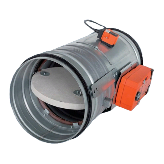
Page 4: Damper Design
"CLOSED". Signalling of blade positions "OPEN" and "CLOSED" is ensured by two firmly set integrated limit switches. Fig. 2 Fire damper FDMC - actuating mechanism Actuating mechanism... - Page 5 TPM 083/12 Fig. 3 Actuating mechanism BELIMO BFL 230-T AC230 V, open-close Notes Caution: Power supply voltage! The actuator must be protected by a fuse that does not exceed 16 A. Parallel connection of other actuators possible. Observe the performance data. Combination of power supply voltage and safety extra-low voltage not permitted N L1 at the both auxiliary switches.
- Page 6 TPM 083/12 2.3. Design with the communication and supply device Design .60 Design with the communication and supply device BKN 230-24 and the actuating mechanism BFL 24-T-ST. It simplifies electrical wiring and interconnection of fire damper. It facilitates on site check and enables central control and checks of fire damper by means of a simple 2-conductor wiring.
-
Page 7: Communication And Control Devices
TPM 083/12 Tab. 2.3.2. Communication and Supply Device BKN 230-24 Communication and Supply Device BKN 230-24 Nominal voltage AC 230V 50/60Hz Power consumption 3,5 W (operating position) Dimensioning 11 VA (including actuating mechanism) Protection Class Degree of protection IP 42 Ambient Temperature - 30 °C …... - Page 8 TPM 083/12 Tab. 3.1.1. BKS 24 -9A contacts K1 and K2 K1 Function Contact Programming K2 Auxiliary Contact Function Interconnection State Situation State K2 contact is on if all the damperss are open Current Failure K2 contact is on if the damper No.
- Page 9 TPM 083/12 3.3. BKS 24-1B communication and control device is used for control and checks of fire dampers with the BFL 24-T-ST actuating mechanism in conjunction with the BKN 230-24 supply and communication device. BKS 24-1B receives information about the situation of the fire damper through the BKN 230-24 supply and communication device and issues controlling commands.
-
Page 10: Dimensions, Weights
TPM 083/12 4. Dimensions, weights 4.1. Dimensions Fig. 9 Fire damper FDMC, design with actuating mechanism BUILT-IN EDGE Position: Damper casing Damper blade Inspection hole covering BAT thermoelectrical starting mechanism Actuating mechanism 4.2. Weight and effective area Tab. 4.2.1. Weight and effective area... -
Page 11: Placement And Assembly
TPM 083/12 4.3. Blades overlaps Tab. 4.3.1 Blades overlaps Blades overlaps Dimension Overlaps FDMC Side without act. mechanism "a" Tab. 4.2.1 Fig. 10 These values has to be respected when projecting related air-conditioning ducts. Fig. 10 Blades overlaps 5. Placement and Assembly 5.1. - Page 12 TPM 083/12 Fig. 11 The distance between the fire damper and the Fig. 12 Built-in edge - design with outer mechanical construction control or actuating mechanism BUILT-IN EDGE min. 200 min. 75 BUILT-IN EDGE BUIL-IN EDGE 5.2. The control mechanism has to be protected (covered) against damage and pollution during installation process.
-
Page 13: Statement Of Installations
TPM 083/12 6. Statement of installations 6.1. Statement of installations the fire dampers FDMB and their fire resistance Tab. 6.1.1. Tab. 6.1.1. Statement of installations Construction Installation Material of stuffing box Figure Mortar or gypsum Wet, installation next to Mortar or gypsum Solid wall wall, ceiling construction... - Page 14 Fig. 15 Solid wall construction - mortar or gypsum EIS 60 ≥ 40 ≥ 100 POSITION: Fire damper FDMC Solid wall construction Mortar or gypsum Duct Fig. 16 Solid wall construction - stuffing box and fire protection mastic EIS 60 ≥...
- Page 15 ● gypsum and mineral wool POSITION: Wool is fixed to damper body and construction by fire protection ● Fire damper FDMC mastic. Mineral wool thickness = construction thickness + 50 mm Mortar or gypsum ● Damper axis has to be horizontal Mineral stone wool min.
- Page 16 Fig. 18 Solid ceiling construction - mortar or gypsum EIS 60 150* ≥ 40 POSITION: Fire damper FDMC * min. 110 - Concrete/ min. 125 - Aerated concrete Solid ceiling construction Mortar or gypsum Duct Fig. 19 Solid ceiling construction - stuffing box and fire protection mastic ≥...
- Page 17 Profil is fixed by screws ≥3,5 mm with corresponding length. Distance between screws ≤200 mm. ≥ 40 POSITION: ≥ 100 Fire damper FDMC Gypsum plate Fire resistant insulation Mortar or gypsum Duct Fig. 21 Gypsum wall construction - stuffing box and fire protection mastic...
- Page 18 Wool is fixed to damper body and construction by fire protection ● POSITION: mastic. Fire damper FDMC Mineral wool thickness = construction thickness + 50 mm ● Damper axis has to be horizontal Mortar or gypsum ●...
-
Page 19: Suspension Of Fire Dampers
TPM 083/12 7. Suspension systems 7.1. Mounting to the ceiling wall Fig. 23 Mounting to the ceiling wall With hinge plate and With Without anchors anchor anchor 1 2 3 Hinge plates Load capacities of threaded hanger rods F [N] at the required fire resistance 90 minutes Weight G [kg] Size... - Page 20 TPM 083/12 Fig. 24 Suspension - horizontal duct Position: Fire damper Damping pad Extension piece Threaded rod Suspension ring Examples of using materials: HILTI, SIKLA, MÜPRO etc. 7.3. Vertical installation Fire dampers can be suspended by using threaded rods and a mounting profiles. Load the suspension system depend on weight of the fire damper.
- Page 21 TPM 083/12 Fig. 25 Suspension - vertical duct Actuating mechanism is placed above the ceiling construction Actuating mechanism is placed under the ceiling construction Notice: Damper must be firmly connected with extension piece by screws or rivets. Suspension ring and mounting Suspension ring and mounting rail rail connected by bolt connected by screw or rivet...
-
Page 22: Technical Data
TPM 083/12 III. TECHNICAL DATA 8. Pressure loss 8.1. Pressure loss calculation [Pa] presure loss [m.s ] air flow speed in nominal damper section [kg.m ] air density coefficient of local pressure loss for the nominal damper section (see Tab. 8.2.1.) 8.2. -
Page 23: Noise Data
TPM 083/12 10. Noise data 10.1. Level of acoustic output corrected with filter A. + 10 log(S) + K [dB(A)] level of acoustic output corrected with filter A [dB] level of acoustic output L related to the 1 m section (see Tab. 10.3.1.) [m ] duct cross section [dB]... - Page 24 -5,3 -8,4 -13,1 -19,5 -27,6 Fig. 26 Calculation example Given data: Fire damper FDMC 250 V = 1000 m .h = 1,2 kg.m Octave range 1000 Hz Tab. 4.2.1. = 0,0374 m Calculation: w [m.s ] = (V [m .h] / 3600) / S [m ] w = 7,43 m.s...
-
Page 25: Material, Finishing
TPM 083/12 IV. MATERIAL, FINISHING 11. Material Damper bodies are supplied in the design made of galvanized plate without any other surface 11.1. finishing. Damper blades are made of fire resistant asbestos free boards made of mineral fibres. Damper controls are made of galvanized materials with no other surface finish. Fasteners is galvanized. -
Page 26: Data Of Product
16.1. Data label is placed on the casing of fire damper. Fig. 27 Data label MANDÍK, a.s. Dobříšská 550 267 24 Hostomice Czech Republic FIRE DAMPER FDMC EI 60 (ve ho i o) S CLASSIFICATION: SIZE: DESIGN: SERIAL NUMBER: WEIGHT (kg):... -
Page 27: Ordering Information
TPM 083/12 IX. ORDERING INFORMATION 18. Ordering key FDMC - .40 TPM 083/12 technical specifications design acc. Tab. 18.1.1. size - Spiro damper SL - Spiro damper with rubber sealing (Lip Seal) type If are requested installation holders it has to be mentioned separately in the order. - Page 28 MANDÍK, a.s. Dobříšská 550 26724 Hostomice Česká republika Tel.: +420 311 706 706 Fax: +420 311 584 810, 311 584 382 E-Mail: mandik@mandik.cz www.mandik.cz Výrobce si vyhrazuje právo na změny výrobku. Aktuální informace o výrobku jsou uvedeny na www.mandik.cz...
Need help?
Do you have a question about the FDMC and is the answer not in the manual?
Questions and answers