
Related Manuals for Kramer AFM-20DSP


Summary of Contents for Kramer AFM-20DSP
- Page 1 USER MANUAL MODELS: AFM-20DSP, AFM-20DSP-LE 20-Port Audio Matrix P/N: 2900-301204 Rev 1 www.kramerAV.com...
-
Page 2: Table Of Contents
AFM-20DSP and AFM-20DSP-LE Rear Panels Mounting AFM-20DSP / AFM-20DSP-LE Connecting the 20-Port Audio Matrix Connecting AFM-20DSP Connecting AFM-20DSP-LE Connecting to AFM-20DSP / AFM-20DSP-LE via RS-232 Operating and Controlling AFM-20DSP/AFM-20DSP-LE Operating via Ethernet Using Embedded Webpages Browsing the AFM-20DSP Webpages Using the Top Status Bar... -
Page 3: Introduction
Kramer Electronics Ltd. Introduction Welcome to Kramer Electronics! Since 1981, Kramer Electronics has been providing a world of unique, creative, and affordable solutions to the vast range of problems that confront the video, audio, presentation, and broadcasting professional on a daily basis. In recent years, we... -
Page 4: Overview
European Advanced Recycling Network (EARN) and will cover any costs of treatment, recycling and recovery of waste Kramer Electronics branded equipment on arrival at the EARN facility. For details of Kramer’s recycling arrangements in your particular country go to our recycling pages at www.kramerav.com/support/recycling. - Page 5 Kramer Electronics Ltd. AFM-20DSP and AFM-20DSP-LE provide exceptional quality, advanced and user-friendly operation, and flexible control. Exceptional Quality • High-Performance, Professional Audio Matrix Switcher – Professional, studio grade signal conversion technology, including the latest generation 32-bit advanced Digital Analog Converter architecture to achieve excellent dynamic performance and improved tolerance to clock jitter.
-
Page 6: Typical Applications
• Maximum Flexibility: ▪ AFM-20DSP: use the default 12x8 I/O matrix configuration or select one of the preset analog I/O configurations. Route any input to any output, even between different formats (for example, route an analog input to an S/PDIF output); control volume and DSP per port; route any of the ports to the power amplifier. -
Page 7: Defining Afm-20Dsp And Afm-20Dsp-Le
• Green when a signal is detected. • Off when no signal is detected. If a signal is detected only on one channel, either left only or right only, the status LED lights green. AFM-20DSP – Defining AFM-20DSP and AFM-20DSP-LE... -
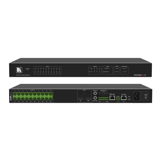
Page 8: Afm-20Dsp And Afm-20Dsp-Le Rear Panels
Press and hold for about 5 seconds to reset the configuration to its default Button parameters. Mains Power Plug in the power cord. Connector and Fuse POWER Illuminated Turn the device on and off. Power Switch AFM-20DSP – Defining AFM-20DSP and AFM-20DSP-LE... -
Page 9: Mounting Afm-20Dsp / Afm-20Dsp-Le
• Reliable earthing of rack-mounted equipment should be maintained. To mount the AFM-20DSP in a rack Attach both rack ears by removing the screws from each side of the machine and replacing those screws through the rack ears or place the machine on a table. -
Page 10: Connecting The 20-Port Audio Matrix
AFM-20DSP-LE devices. Connecting AFM-20DSP Always switch off the power to each device before connecting it to your AFM-20DSP. After connecting your AFM-20DSP, connect its power and then switch on the power to each device. Figure 5: Connecting to the AFM-20DSP Rear Panel... - Page 11 2. Connect the PORT balanced mono 3-pin terminal block connectors (port I/O is set to 12x8 in this example) to the following audio acceptors: ▪ Ports 13 and 14 to powered speakers (for example, Kramer Tavor 6-O). ▪ Port 15 to a power amplifier with speakers.
-
Page 12: Connecting Afm-20Dsp-Le
Kramer Electronics Ltd. Connecting AFM-20DSP-LE Always switch off the power to each device before connecting it to your AFM-20DSP-LE. After connecting your AFM-20DSP-LE, connect its power and then switch on the power to each device. Figure 6: Connecting to the AFM-20DSP-LE Rear Panel... -
Page 13: Connecting To Afm-20Dsp / Afm-20Dsp-Le Via Rs-232
Kramer Electronics Ltd. Connecting to AFM-20DSP / AFM-20DSP-LE via RS-232 You can connect to the AFM-20DSP via an RS-232 connection using, for example, a PC. AFM-20DSP features an RS-232 3-pin terminal block connector allowing the RS-232 to control the AFM-20DSP. -
Page 14: Operating And Controlling Afm-20Dsp/Afm-20Dsp-Le
2. Click Change Adapter Settings. 3. Highlight the network adapter you want to use to connect to the device and click Change settings of this connection. The Local Area Connection Properties window for the selected network adapter appears. AFM-20DSP – Operating and Controlling AFM-20DSP/AFM-20DSP-LE... - Page 15 (TCP/IPv4) depending on the requirements of your IT system. 5. Click Properties. The Internet Protocol Properties window relevant to your IT system appears as shown in Figure 8 Figure Figure 8: Internet Protocol Version 4 Properties Window AFM-20DSP – Operating and Controlling AFM-20DSP/AFM-20DSP-LE...
- Page 16 You can connect the Ethernet port of the AFM-20DSP to the Ethernet port on a network hub or using a straight-through cable with RJ-45 connectors. Configuring the Ethernet Port You can set the Ethernet parameters via the embedded webpages. AFM-20DSP – Operating and Controlling AFM-20DSP/AFM-20DSP-LE...
-
Page 17: Using Embedded Webpages
58. Some of the same tasks can be carried out via DSP, Matrix and Mixer pages, for your convenience. For example, you can link analog input and output pairs through any of these 3 pages. AFM-20DSP – Using Embedded Webpages... -
Page 18: Browsing The Afm-20Dsp Webpages
Kramer Electronics Ltd. Browsing the AFM-20DSP Webpages To browse the AFM-20DSP webpages: 1. Open your Internet browser. 2. Type the IP Address of the device in the Address bar of your browser. For example, the default IP Address: 3. The authentication page appears. - Page 19 Kramer Electronics Ltd. 5. Click Sign in. The Main webpage appears. Figure 12: AFM-20DSP Main Page with Navigation List on Left AFM-20DSP – Using Embedded Webpages...
-
Page 20: Using The Top Status Bar
Use the top status bar to perform the following functions: • Viewing/Changing Current Analog I/O Configuration and Preset Name on page 19. • Changing Security Settings on page 19. • Entering/exiting full-screen display view by clicking the display-view icon ( AFM-20DSP – Using Embedded Webpages... - Page 21 1. Click the lock icon ( ) indicating that security is enabled. The following message appears: Figure 16: Disabling Security Message 2. Type the current password (Admin, by default). 3. Click Save. Security is disabled. To enable security settings: • Click the security disabled icon ( AFM-20DSP – Using Embedded Webpages...
-
Page 22: Viewing The Matrix Area
The matrix area in the DSP page shows the inputs that are currently routed to the outputs. Figure 17: DSP Page – Matrix Area Clicking an IN or OUT button or a module, highlights the routing path. Figure 18: Matrix Area – Routing Path AFM-20DSP – Using Embedded Webpages... - Page 23 Kramer Electronics Ltd. When opening the processing view, the sliders of the Inputs routed to the outputs appear. Figure 19: Processing View – Inputs Routed to Outputs AFM-20DSP – Using Embedded Webpages...
-
Page 24: Processing Audio Signals
1. In the Navigation pane, click DSP. The DSP (Main) page appears. 2. Click the Duplicate to Amplifier Output 1 drop-down box and select an output (for example, OUT 19). Figure 20: DSP Page – Selecting Left Amplifier Output Signal AFM-20DSP – Processing Audio Signals... -
Page 25: Linking Analog Inputs And Outputs
You can also link audio analog audio pairs via the Matrix page, and Mixer page. 2. Click the link on the side of the ports (IN 7 and IN 8 in this example). Figure 23: DSP Page – Linking Analog Audio Ports The selected inputs are linked. AFM-20DSP – Processing Audio Signals... -
Page 26: Processing A Signal
32. • Using Gain Module on page 33. • Using Post Matrix Equalizer Module on page 35. • Using LPF (Low Pass Filter) on page 35. • Using Limit Module on page 36. AFM-20DSP – Processing Audio Signals... - Page 27 • Current fader position – shows the current position of the fader. You can also type the desired volume level into this box and press Enter on your PC. Figure 25: Channel Fader AFM-20DSP – Processing Audio Signals...
- Page 28 (used for troubleshooting). ▪ Click to select audio line in. ▪ Click to select dynamic microphone and to select condenser microphone (the title IN changes to MIC). Analog input parameters are adjusted. AFM-20DSP – Processing Audio Signals...
- Page 29 The levels of audio signals that fall below the set threshold level are reduced. To adjust the expander module: 1. In the Navigation pane, click DSP. The DSP (Main) page opens. 2. Click Exp. The button turns light blue and the Expander module page appears. AFM-20DSP – Processing Audio Signals...
- Page 30 1. In the Navigation pane, click DSP. The DSP (Main) page appears. 2. Click HPF. The button turns light orange and the High Pass Filter module page appears. The left side shows the input volume slider. AFM-20DSP – Processing Audio Signals...
- Page 31 Designed to have a frequency response as flat as possible in the passband. 6. Select the HPF slope (24, 18, 12 or 6dB/Oct) – set the filter drop-off per octave from the filter frequency. HPF parameters are adjusted. AFM-20DSP – Processing Audio Signals...
- Page 32 Notch Step Size – Sets the decrease in dB steps until reaching Max depth. ▪ Default Bandwidth (Oct) – Sets the width of the notch. ▪ Recycle Delay – Sets time period [Hours] until the filters are reused. AFM-20DSP – Processing Audio Signals...
- Page 33 1. In the Navigation pane, click DSP. The DSP (Main) page appears. 2. Click Comp. The button turns blue and the Compressor module pane appears. 3. Click the Off button . The Comp module turns on Figure 33: Processing View – Compressor Module AFM-20DSP – Processing Audio Signals...
- Page 34 Click BYPASS to ignore a band. ▪ Adjust the band Frequency (Hz). ▪ Set Bandwidth (Oct) to set the range of frequencies around the selected frequency. ▪ Set the bandwidth audio Level (dB). Equalizer settings are adjusted. AFM-20DSP – Processing Audio Signals...
- Page 35 2. Click Gain. The button turns violet and the Gain processing page appears. Figure 36: Processing View – Gain Module 3. Perform the following actions: ▪ Set gain. ▪ Click Mute if required. Gain is adjusted. AFM-20DSP – Processing Audio Signals...
- Page 36 Move the volume fader to set the output audio level (both sliders are identical). ▪ Toggle to mute / unmute the output audio, respectively. ▪ Click to inverse polarity (used for troubleshooting). Audio outputs are adjusted. AFM-20DSP – Processing Audio Signals...
- Page 37 1. In the Navigation pane, click DSP. The DSP (Main) page appears. 2. Click LPF. The button turns peach and the Low Pass Filter processing page appears. The left side shows the input volume slider. AFM-20DSP – Processing Audio Signals...
- Page 38 4. Set the Threshold. Note the Gain Reduction meter as you change the threshold. 5. Set the Release time to set the response speed of the limiter to signal levels above the threshold. Limiter settings are adjusted. AFM-20DSP – Processing Audio Signals...
-
Page 39: Routing Inputs To Outputs
Setting Amplifier Outputs on page 40. Connecting Inputs to Outputs To route an input or several inputs to an output: 1. In the Navigation pane, click Matrix. The Matrix page appears. Figure 41: Matrix Page AFM-20DSP – Processing Audio Signals... - Page 40 3. Click any other cross-points (one input to output/s or several inputs to output/s). Figure 43: Matrix Page – Multiple Input-Output Cross-Point Selected inputs are routed to selected outputs. You can also select an audio signal generator for testing. AFM-20DSP – Processing Audio Signals...
- Page 41 Figure 44: Matrix Page – Setting Cross-Point Volume 3. Set the cross-point volume (using the knob or entering the value and pressing Enter on your keyboard). The cross-point volume is set and appears at the cross-point. Figure 45: Cross-Point Volume Value AFM-20DSP – Processing Audio Signals...
- Page 42 Figure 46: AMP View 3. Select an output to route to Amp 1 (amplifier left side) and to Amp 2 (amplifier right side). the button lights green. Figure 47: Selecting Outputs to Amplifier Amplifier outputs are defined. AFM-20DSP – Processing Audio Signals...
-
Page 43: Mixing Audio Signals
2. Use the slider or enter the desired value and press Enter (on your PC) to set the volume. View the current gain and the input/output name (see Input / Output Channels Operation on page 25). AFM-20DSP – Processing Audio Signals... - Page 44 Store a snapshot (inputs, outputs and amplifier) to store the current configuration state, recall a snapshot, set to default or clear a snapshot. Storing Snapshots To store a snapshot: 1. In the Navigation pane, click Mixer. The Mixer page appears. 2. Set input and output mixers. AFM-20DSP – Processing Audio Signals...
- Page 45 1. In the Navigation pane, click Mixer. The Mixer page appears. 2. Click Clear. Snapshot buttons turn blue. Figure 53: Mixer Page – Clearing a Snapshot 3. Select the snapshot to be cleared. The snapshot cleared returns to its default values. AFM-20DSP – Processing Audio Signals...
- Page 46 ▪ Click Prev to load the previous snapshot configuration. ▪ Click Last to load the latest configured snapshot (clicking Last again goes to the previously configured snapshot and so on). The selected snapshot is loaded. AFM-20DSP – Processing Audio Signals...
-
Page 47: Defining Audio Settings
AFM-20DSP analog audio I/O configuration, system presets and amplifier settings using the A/V Settings page. Amplifier settings are only relevant to AFM-20DSP. To define audio settings: 1. In the Navigation pane, click A/V Settings. The A/V Settings page appears. Figure 54: A/V Settings Page 2. -
Page 48: Defining Video Settings
3. Enter HDMI input and output labels then click Set. 4. For HDMI input, check/uncheck Force RGB and/or Force 2LPCM. 5. If required, select a video pattern from the drop-down box. Video settings are defined. AFM-20DSP – Defining Video Settings... -
Page 49: Restarting And Resetting The Device
1. In the Navigation pane, click Settings. The Settings page appears. Figure 56: Settings Page 2. Click Restart. The device restarts immediately. Wait for the device to reload after device restart. There is no message before restarting. AFM-20DSP – Restarting and Resetting the Device... - Page 50 1. In the Navigation pane, click Settings. The Settings page appears. 2. Click Factory reset. The following message appears: Figure 57: Settings Page – Factory Reset Message 3. Click Yes. The device resets to its factory default parameters. AFM-20DSP – Restarting and Resetting the Device...
-
Page 51: Defining Settings
By default, the webpages are secured and require access permission (user name and password are both: Admin). AFM-20DSP enables performing the following security actions: • Disabling Security on page 50. • Enabling Security on page 51. • Changing the Password on page 51. AFM-20DSP – Defining Settings... - Page 52 Figure 59: General Settings Tab – Security 2. Click Off. The following message appears. Figure 60: General Settings Tab – Security Message 3. Enter the current password and click Save. Security is disabled. The security-disabled icon appears ( AFM-20DSP – Defining Settings...
- Page 53 1. In the Navigation pane, click Settings. The Settings page appears, displaying the Security area (see Figure 59). 2. Enable security (if disabled). 3. Enter current password and new password as required. Figure 62: General Settings Tab – Changing the Password AFM-20DSP – Defining Settings...
-
Page 54: Defining Communication Settings
53. Changing Ethernet Settings To change the Ethernet settings: 1. In the Navigation pane, click Settings. The General tab in the Settings page appears. 2. Select the Communication tab: Figure 64: Settings Page – Communication Tab AFM-20DSP – Defining Settings... - Page 55 4. Set DHCP to ON. 5. Click Save. 6. Type the device name in the address bar of your browser to reload the page. You can read the new IP address from the Communication Settings page. Parameters are set. AFM-20DSP – Defining Settings...
-
Page 56: Performing Firmware Upgrade
Figure 67: Upgrade Settings Tab – Firmware Upgrade Message 4. Click Yes. Wait for completion of the upgrade process: Figure 68: Upgrade Settings Tab – Firmware Upgrade Process 5. Wait for the device to restart. Firmware upgrade is complete. AFM-20DSP – Defining Settings... -
Page 57: Setting Date And Time
1. In the Navigation pane, click Settings. The General tab in the Settings page appears. 2. Select the Time and date tab. Figure 69: Settings Page – Time and Date Tab 3. Set Device Date and click OK. Figure 70: Time and Date Settings Tab – Setting Device Date AFM-20DSP – Defining Settings... -
Page 58: Configuring Device Automation
Note that all the ports, actions and triggers that are relevant to AFM-20DSP are included in the Kramer Maestro, as well as ports, actions and triggers that are relevant to other Kramer devices. The Panel tab in the Automation page is currently unavailable. - Page 59 1. In the Navigation pane, click Automation. The Maestro page appears. Figure 72: Automation Page 2. Configure the ports, actions, scripts and triggers as described in the Kramer Maestro User Manual. Once the triggers are defined, the trigger activates the scripts configured in the automation page.
-
Page 60: Viewing Device Information
Kramer Electronics Ltd. Viewing Device Information In the Navigation pane, click About to view the AFM-20DSP webpage version and Kramer Electronics Ltd details. Figure 73: About Page AFM-20DSP – Viewing Device Information... -
Page 61: Upgrading Firmware
The latest version of K-UPLOAD and installation instructions can be downloaded from our website at: www.kramerav.com/support/product_downloads.asp. Note that in order to use the micro USB port, you need to install the Kramer USB driver, available at: www.kramerav.com/support/product_downloads.asp. AFM-20DSP – Upgrading Firmware... -
Page 62: Technical Specifications
4K UHD @60Hz (4:2:0) 24bpp resolution Compliance HDMI and HDCP 1.4 User Interface Front Panel LEDs 1 status, 20 analog audio ports, 4 Dante I/O, HDMI embed, HDMI de–embed, 2 S/PDIF I/O, and 2 amplifier channels AFM-20DSP – Technical Specifications... -
Page 63: Afm-20Dsp-Le Technical Specs
Crosstalk <-85 dB, 20Hz to 20kHz User Interface Front Panel LEDs 1 status, 20 analog audio ports, 4 Dante I/O, HDMI embed, HDMI de–embed, 2 S/PDIF I/O, and 2 amplifier channels Control RS-232 Baud Rate 115200 AFM-20DSP – Technical Specifications... - Page 64 Shipping Dimensions (W, D, H) 52.5cm x 33cm x 10.7cm (20.7" x 13" x 4.2") Net Weight 1.6kg (3.5lbs) Shipping Weight 2.7kg (5.9lbs) approx. Accessories Included Power cord Specifications are subject to change without notice at www.kramerav.com AFM-20DSP – Technical Specifications...
-
Page 65: Default Communication Parameters
640 x 480p at 72Hz - VESA 640 x 480p at 75Hz - VESA 800 x 600p at 56Hz - VESA 800 x 600p at 60Hz - VESA 800 x 600p at 72Hz - VESA 800 x 600p at 75Hz - VESA AFM-20DSP – Technical Specifications... - Page 66 Front left/right center.. No Rear left/right center... No Rear LFE....No Report information Date generated... 03/04/2017 Software revision..2.90.0.1020 Data source....File Operating system..6.1.7601.2.Service Pack 1 Raw data 00,FF,FF,FF,FF,FF,FF,00,2D,B2,00,12,01,01,01,01,FF,18,01,03,80,34,20,78,E2,B3,25,AC,51,30,B4,26, 10,50,54,FF,FF,80,81,8F,81,99,A9,40,61,59,45,59,31,59,71,4A,81,40,01,1D,00,72,51,D0,1E,20,6E,28, 55,00,07,44,21,00,00,1E,00,00,00,FF,00,32,39,35,2D,38,38,33,34,35,30,31,30,30,00,00,00,FC,00,56, 53,2D,38,38,55,54,0A,20,20,20,20,20,00,00,00,FD,00,38,4C,1E,53,11,00,0A,20,20,20,20,20,20,01,E6, 02,03,1B,C1,23,09,07,07,48,10,05,84,03,02,07,16,01,65,03,0C,00,10,00,83,01,00,00,02,3A,80,18,71, 38,2D,40,58,2C,45,00,07,44,21,00,00,1E,01,1D,80,18,71,1C,16,20,58,2C,25,00,07,44,21,00,00,9E,01, 1D,00,72,51,D0,1E,20,6E,28,55,00,07,44,21,00,00,1E,8C,0A,D0,8A,20,E0,2D,10,10,3E,96,00,07,44,21, 00,00,18,00,00,00,00,00,00,00,00,00,00,00,00,00,00,00,00,00,00,00,00,00,00,00,00,00,00,00,00,77 AFM-20DSP – Technical Specifications...
-
Page 67: Protocol 3000
Kramer Electronics Ltd. Protocol 3000 Kramer devices can be operated using Kramer Protocol 3000 commands sent via serial or Ethernet ports. Understanding Protocol 3000 Protocol 3000 commands are a sequence of ASCII letters, structured according to the following. • Command format:... -
Page 68: Protocol 3000 Commands
– HPD status according to FEEDBACK signal validation ~nn@DISPLAYout_id,status<CR><LF> 0 – Signal or sink is not valid 1 – Signal or sink is valid 2 – Sink and EDID is valid DSP-ACTION Internal – for web only. Set DSP parameter. AFM-20DSP – Protocol 3000... - Page 69 Get command list or COMMAND Get the command list: #HELP<CR> #HELP<CR> help for specific command command. #HELPcommand_name<CR> To get help for FEEDBACK AV-SW-TIMEOUT: 1. Multi-line: HELPAV-SW-TIMEOUT<CR> ~nn@Devicecommand,command…<CR><LF> To get help for command use: HELP (COMMAND_NAME)<CR><LF> ~nn@HELPcommand:<CR><LF> description<CR><LF> USAGE:usage<CR><LF> AFM-20DSP – Protocol 3000...
- Page 70 #MODEL?<CR> printable ASCII chars #MODEL?<CR> This command FEEDBACK identifies equipment ~nn@MODELmodel_name<CR><LF> connected to AFM- 20DSP and notifies of identity changes to the connected equipment. The Matrix saves this data in memory to answer REMOTE- INFO requests. AFM-20DSP – Protocol 3000...
- Page 71 #NET-CONFIG?id<CR> interface (if there are more than one). #NET-CONFIG?id<CR> Counting is 0 based, meaning the FEEDBACK control port is ‘0’, additional ports are ~nn@NET-CONFIGid,ip,net_mask,gateway<CR><LF> 1,2,3…. – Network IP – Network mask net_mask – Network gateway gateway AFM-20DSP – Protocol 3000...
- Page 72 Set the subnet mask to For proper settings 255.255.0.0: #NET-MASKnet_mask<CR> #NET- consult your network FEEDBACK MASK255.255.000.000<CR administrator. ~nn@NET-MASKnet_mask<CR><LF> > net_mask – Format: xxx.xxx.xxx.xxx NET-MASK? Get subnet mask. COMMAND Get the subnet mask: #NET-MASK?<CR> #NET-MASK?<CR> FEEDBACK ~nn@NET-MASKnet_mask<CR><LF> AFM-20DSP – Protocol 3000...
- Page 73 – Indicates a specific channel number when there are multiple channels of the same type – 14 decimal digits, serial_number Get device serial COMMAND Get the device serial number: number. factory assigned #SN?<CR> #SN?<CR> FEEDBACK ~nn@SNserial_number<CR><LF> AFM-20DSP – Protocol 3000...
- Page 74 Extended Protocol 1<CR> ▪ – <port_type> FEEDBACK 3000 command. o AMPLIFIED_AUDIO ~nn@X-AUD-HI-Z? <direction_type>.<port_type>.<port_index>,<HiZState ▪ <port_index> – 1 0:OFFN,1:ON>,<HiZVolt 0:70v,1:100v><CR><LF> ▪ – <hizstate> o 0– Off o 1– On ▪ – <hizvolt> 0 – 70v 1 – 100v AFM-20DSP – Protocol 3000...
- Page 75 In the future, data pattern will be also supported to generate some data on RS232 lines. This is an Extended Protocol 3000 command. AFM-20DSP – Protocol 3000...
- Page 76 X- sensitive) LINK-GROUP – also includes: signal_id ▪ – <signal_type> o ANALOG_AUDIO This is an – 1 ▪ <index> Extended Protocol ▪ – OFF/ON (not case state 3000 command. Used essentially by the sensitive) AFM-20DSP – Protocol 3000...
- Page 77 – The port number <port_index> as printed on the front or rear panel ▪ – <signal_type> o AUDIO ▪ <index> – Indicates a specific channel number when there are multiple channels of the same type ▪ – <mute_state> AFM-20DSP – Protocol 3000...
- Page 78 – ▪ <signal_type> o VIDEO o AUDIO ▪ <index> – Indicates a specific channel number when there are multiple channels of the same type – OFF/ON (not case sensitive) state AFM-20DSP – Protocol 3000...
- Page 79 5: Vertical RGB colors bar o 6: H grey scale o 7: Split Bar o 8: BW-12 (Vertical mixed bar o 9: Cross chess B&W o 10: Black squares chess 11: V grey scale split bar AFM-20DSP – Protocol 3000...
- Page 80 <LF> product use the IOConfig.SYSTEM.MIXER,[ IOCONFIG.SYSTEM.MIXER command: 2:Snapshot%201:OFF]<CR> ▪ –preset index <preset_id> X-PRST-TYPES? <LF> ▪ – the name of the preset in <name> This is an Extended URL encode format Protocol 3000 ▪ – <lock_state> command. AFM-20DSP – Protocol 3000...
- Page 81 Presets inside the URL encode format (no spaces) same system. To get the list of preset types existing in your product use the command: X-PRST-TYPES? This is an Extended Protocol 3000 command. AFM-20DSP – Protocol 3000...
- Page 82 This is used essentially when we have different types of Presets inside the same system. To get the list of preset types existing in your product use the command: X-PRST-TYPES? This is an Extended Protocol 3000 command. AFM-20DSP – Protocol 3000...
- Page 83 This is used essentially when we have different types of Presets inside the same system. To get the list of preset types existing in your product use the command: X-PRST-TYPES? This is an Extended Protocol 3000 command. AFM-20DSP – Protocol 3000...
- Page 84 PIPE? configuration for an output port. This is when we want to “tee” a signal to another output. Used essentially into AFM-20DSP to output audio signal to AMPLIFIED outputs. This is an Extended Protocol 3000 command. AFM-20DSP – Protocol 3000...
-
Page 85: Result And Error Codes
(Reserved) ERR_RESERVED_8 (Reserved) ERR_RESERVED_9 (Reserved) ERR_RESERVED_10 (Reserved) ERR_RESERVED_11 (Reserved) ERR_RESERVED_12 (Reserved) ERR_EDID_CORRUPTED EDID corrupted ERR_NON_LISTED Device specific errors File has the same CRC – no changed ERR_SAME_CRC ERR_WRONG_MODE Wrong operation mode ERR_NOT_CONFIGURED Device/chip was not initialized AFM-20DSP – Protocol 3000... - Page 86 Electronics products, this product must be insured during shipment, with the insurance and shipping charges prepaid by you. If this product is returned uninsured, you assume all risks of loss or damage during shipment. Kramer Electronics will not be responsible for any costs related to the removal or re- installation of this product from or into any installation.
- Page 87 SAFETY WARNING Disconnect the unit from the power supply before opening and servicing For the latest information on our products and a list of Kramer distributors, visit our Web site where updates to this user manual may be found. We welcome your questions, comments, and feedback.
Need help?
Do you have a question about the AFM-20DSP and is the answer not in the manual?
Questions and answers