
Related Manuals for Kramer VS-88A


Summary of Contents for Kramer VS-88A
- Page 1 Kramer Electronics, Ltd. USER MANUAL Models: VS-88A, 8 x 8 Balanced Audio Matrix Switcher VS-88V, 8 x 8 Video Matrix Switcher SD-7588V, 8 x 8 SDI Matrix Switcher...
-
Page 2: Table Of Contents
Introduction Getting Started Quick Start Overview Your Matrix Switchers Your VS-88A 8 x 8 Balanced Audio Matrix Switcher Your VS-88V 8x8 Video Matrix Switcher Your SD-7588V 8x8 SDI Matrix Switcher Installing in a Rack Connecting Your 88 Series Matrix Switchers... - Page 3 Figure 11: Component Switcher: VS-88V Group Connection Figure 12: Rear Panel DIP-switches Tables Table 1: VS-88A 8x8 Balanced Audio Matrix Switcher Features Table 2: VS-88V 8x8 Video Matrix Switcher Features Table 3: SD-7588V 8x8 SDI Matrix Switcher Features Table 4: Rear Panel DIP-switches...
-
Page 4: Introduction
2 We recommend that you use only the power cord supplied with this device 3 Downloadable from our Web site at http://www.kramerelectronics.com 4 Download up-to-date Kramer user manuals from the Internet at this URL: http://www.kramerelectronics.com 5 The complete list of Kramer cables is on our Web site at http://www.kramerelectronics.com... -
Page 5: Quick Start
Getting Started Quick Start This quick start chart summarizes the basic setup and operation steps. KRAMER: SIMPLE CREATIVE TECHNOLOGY... -
Page 6: Overview
1 However, you cannot connect two or more inputs to a single output 2 Available from Kramer Electronics on our Web site at http://www.kramerelectronics.com 3 Switchers in the 88 Series share identical front panel controls. The VS-88V and SD-7588V have rear panel BNC connectors. -
Page 7: Your Vs-88A 8 X 8 Balanced Audio Matrix Switcher
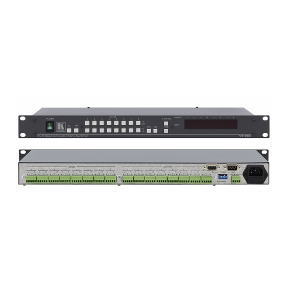
RS-232 and RS-485 interfaces Includes 15 preset memory locations for quickly and easily accessing the most frequently used configurations Functions as a standalone unit as well as part of a Kramer multi- signal switcher system Figure 1 and Table 1 define the VS-88A: 1 Which includes digital and analog video, digital and analog audio and RS-422 control switchers. -
Page 9: Table 1: Vs-88A 8X8 Balanced Audio Matrix Switcher Features
Your Matrix Switchers Table 1: VS-88A 8x8 Balanced Audio Matrix Switcher Features Feature Function POWER Switch Illuminated switch supplying power to the unit ALL Button Pressing ALL before pressing an IN button, connects that input to all outputs OFF Button Pressing OFF after pressing an OUT button disconnects that output from the inputs. -
Page 10: Your Vs-88V 8X8 Video Matrix Switcher
Includes 15 preset memory locations for quickly and easily accessing the most frequently used configurations Functions as a standalone unit as well as part of a Kramer multi- signal switcher system Can be combined as part of a group of VS-88V switchers that... -
Page 11: Figure 2: Vs-88V 8X8 Video Matrix Switcher
Your Matrix Switchers Figure 2: VS-88V 8x8 Video Matrix Switcher KRAMER: SIMPLE CREATIVE TECHNOLOGY... -
Page 12: Table 2: Vs-88V 8X8 Video Matrix Switcher Features
Your Matrix Switchers Table 2: VS-88V 8x8 Video Matrix Switcher Features Feature Function POWER Switch Illuminated switch supplying power to the unit ALL Button (ALL= All Outputs) Pressing ALL before pressing an INPUT button, connects that input to all outputs OFF Button (OFF= All Inputs) Pressing OFF after pressing an OUTPUT button disconnects that output from the inputs. -
Page 13: Your Sd-7588V 8X8 Sdi Matrix Switcher
RS-232 and RS-485 interfaces Includes 15 preset memory locations for quickly and easily accessing the most frequently used configurations Functions as a standalone unit as well as part of a Kramer multi- signal switcher system Figure 3 and Table 3 define the SD-7588V: 1 Which includes digital and analog video, digital and analog audio, and RS-422 control switchers. -
Page 14: Figure 3: Sd-7588V 8X8 Sdi Matrix Switcher
Your Matrix Switchers Figure 3: SD-7588V 8x8 SDI Matrix Switcher... -
Page 15: Table 3: Sd-7588V 8X8 Sdi Matrix Switcher Features
5 Push in to terminate the SYNC line. Push out when the line extends to another unit 6 The 88 Series RS-485 connector has 4 pins, and the Remote Controller RS-485 connector has just 3 pins 7 If the unit is the final unit in the daisy-chain connection, no termination is required KRAMER: SIMPLE CREATIVE TECHNOLOGY... -
Page 16: Installing In A Rack
5. The machine is earthed (grounded) in a reliable way power and is connected only to an electricity socket with If you are using a Kramer rack grounding. Pay particular attention to situations where adapter kit (for a machine that is not electricity is supplied indirectly (when the power cord 19"), see the Rack Adapters user... -
Page 17: Connecting Your 88 Series Matrix Switchers
Connecting Your 88 Series Matrix Switchers Connecting Your 88 Series Matrix Switchers This section describes how to connect: A VS-88A standalone unit (see section 6.1) A VS-88V standalone unit (see section 6.2) An SD-7588V standalone unit (see section 6.3) A balanced or unbalanced stereo audio input or output (see section Several units and the PC (see section 6.5) -
Page 18: Connecting A Vs-88A
Connecting Your 88 Series Matrix Switchers Connecting a VS-88A To connect the VS-88A as shown in Figure 4: 1. Connect up to 8 balanced stereo audio sources (for example, balanced stereo audio players) to INPUT terminal blocks 1 to 8. -
Page 19: Connecting A Vs-88V
7.2.1). The IN SYSTEM button is non responsive. Figure 5: Connecting the VS-88V 1 You are not required to connect all inputs or outputs 2 We recommend that you use only the power cord that is supplied with this machine KRAMER: SIMPLE CREATIVE TECHNOLOGY... -
Page 20: Connecting An Sd-5788V
Connecting Your 88 Series Matrix Switchers Connecting an SD-5788V To connect the SD-5788V as shown in Figure 6: 1. Connect up to 8 SDI digital video sources (for example, SDI video players) to INPUT BNC connectors 1 to 8 2. Connect up to 8 SDI digital video acceptors (for example, SDI displays) to OUTPUT BNC connectors 1 to 8 3. -
Page 21: Connecting The Stereo Audio Input/Output
RS-232 and the RS-485 connected in a parallel line: 1 The 88 Series firmware complies with Kramer Protocol 2000 (version 3.1 and higher) 2 Make one-to-one connections (that is, uncrossed) 3 Often the PC has no RS-485 Com port and so both are required simultaneously... -
Page 22: Connecting A Component, Y/C, Rgbs Or Rgbhv Switcher
Connecting Your 88 Series Matrix Switchers Figure 10: System Connection: Switchers and the PC Connecting a Component , Y/C, RGBS or RGBHV Switcher A component switcher consists of three VS-88V switchers, interconnected as one group, with one of the switchers set as the Master. A component switcher can function in the IN SYSTEM or standalone mode. -
Page 23: Operation
This section describes the modes, setup, and the operation of the devices using the front panel controls. ® For instructions on using the Windows -based Kramer control software, refer to the separate user manual , Kramer Control Software. Understanding Modes A switcher operates in two System modes: Standalone and IN SYSTEM and in two Confirmation modes: AT ONCE and CONFIRM. -
Page 24: System Modes
Operation 7.1.1 System Modes By default, a switcher starts in the standalone mode and the IN SYSTEM key does not illuminate. Pressing the IN SYSTEM key twice toggles to the IN SYSTEM mode. In the standalone mode: The switcher implements actions independently and separately from the others In the IN SYSTEM mode: Several switchers with different kinds of signals are connected as... -
Page 25: Setup Information
OFF ON OFF ON OFF OFF ON OFF ON OFF ON OFF ON OFF OFF ON OFF OFF OFF ON 1 Helpful, for example, when using three composite video switchers to form one component video switcher KRAMER: SIMPLE CREATIVE TECHNOLOGY... -
Page 26: Setup Capacity
Operation 7.2.2 Setup Capacity From every switcher you can store up to 8 setups. From the PC you can store up to 15 setups. 7.2.3 Switching the Power On To switch the power on at all the switchers, do the following: 1. -
Page 27: Recalling A Setting
3 Locking means that the front panel is locked. The switcher still operates via the PC 4 Especially if the system is complex and the switchers are stored on a rack in another room 5 Restarting a switcher also releases the protection mechanism (without wiping out the switcher settings) KRAMER: SIMPLE CREATIVE TECHNOLOGY... -
Page 28: Table 7: Technical Specifications For The Vs-88A
Technical Specifications Table 7: Technical Specifications for the VS-88A INPUTS: 8 balanced stereo audio, +4 dBm/33k on detachable terminal blocks OUTPUTS: 8 balanced audio stereo, +4 dBm/50 Vpp max) on detachable terminal blocks AUDIO BANDWIDTH: > 40 kHz; 0.3db AUDIO CROSSTALK: <... - Page 30 For the latest information on our products and a list of Kramer distributors, visit our Web site: www.kramerelectronics.com, where updates to this user manual may be found. We welcome your questions, comments and feedback. Safety Warning: Disconnect the unit from the power supply before opening/servicing.
Need help?
Do you have a question about the VS-88A and is the answer not in the manual?
Questions and answers