
Related Manuals for Kramer AFM-20DSP-LE


Summary of Contents for Kramer AFM-20DSP-LE
- Page 1 USER MANUAL MODELS: AFM-20DSP, AFM-20DSP-LE, AFM-20DSP-AEC 20-Port Audio Matrix P/N: 2900-301204 Rev 3 www.kramerAV.com...
-
Page 2: Table Of Contents
Kramer Electronics Ltd. Contents Introduction Getting Started Overview Typical Applications Defining AFM-20DSP AFM-20DSP, AFM-20DSP-AEC Front Panels AFM-20DSP-LE Front Panel AFM-20DSP/LE/AEC Rear Panels Installing AFM-20DSP Connecting the 20-Port Audio Matrix Connecting AFM-20DSP Connecting AFM-20DSP-LE Connecting AFM-20DSP-AEC Connecting to AFM-20DSP via RS-232... -
Page 3: Introduction
Introduction Welcome to Kramer Electronics! Kramer Electronics provides a world of creative and affordable audio and visual solutions for the AV industry. At Kramer, we go beyond the box with end-to-end solutions that blend cutting-edge cloud technologies, advanced software, and dependable hardware. -
Page 4: Overview
European Advanced Recycling Network (EARN) and will cover any costs of treatment, recycling and recovery of waste Kramer Electronics branded equipment on arrival at the EARN facility. For details of Kramer’s recycling arrangements in your particular country go to our recycling pages at https://www.kramerav.com/il/quality/environment. - Page 5 Most of the information included in this user manual is relevant to AFM-20DSP, AFM-20DSP-LE, and AFM-20DSP-AEC. Sections referring to Dante, HDMI, S/PDIF, and amplifier ports (in the embedded webpages and Protocol 3000 sections) are not relevant to AFM-20DSP-LE. or “device”, when used by itself throughout this Unless specified otherwise, AFM-20DSP manual, refers to all three devices.
-
Page 6: Typical Applications
S/PDIF output); control volume and DSP per port; route any of the ports to the power amplifier. ▪ AFM-20DSP-LE: use the default 12 x8 I/O matrix configuration or select one of the preset analog I/O configurations. ▪... -
Page 7: Defining Afm-20Dsp
Kramer Electronics Ltd. Defining AFM-20DSP This section defines AFM-20DSP/LE/AEC front panels. AFM-20DSP, AFM-20DSP-AEC Front Panels Figure 1: AFM-20DSP and AFM-20DSP-AEC Front Panel AFM-20DSP-LE Front Panel Figure 2: AFM-20DSP-AEC Front Panel Feature Function STATUS LED Indicates system status: Almost 3 cycles of red/blue/off/green... -
Page 8: Afm-20Dsp/Le/Aec Rear Panels
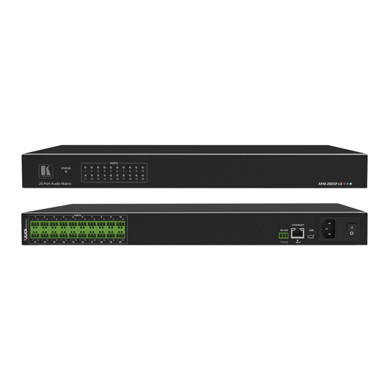
• Off when no signal is detected. In the webpage, Ch1 and CH2 are referred to as AMP 1 and AMP 2, respectively. AFM-20DSP/LE/AEC Rear Panels Figure 3: AFM-20DSP Rear Panel Figure 4: AFM-20DSP-LE Rear Panel Figure 5: AFM-20DSP-AEC Rear Panel Feature Function PORTS 3-pin Interchangeable balanced mono audio ports. - Page 9 Kramer Electronics Ltd. Feature Function S/PDIF OUT RCA Connect to a digital stereo audio acceptor. Connector S/PDIF IN RCA Connect to a digital stereo audio source. Connector SPEAKER OUT Outputs two selected audio signals in two channels. For Lo-Z: connect stereo output to Lo-Z speakers: L+ and L- to the left speaker;...
-
Page 10: Installing Afm-20Dsp
Kramer Electronics Ltd. Installing AFM-20DSP This section provides instructions for installing AFM-20DSP. Before you start the installation, make sure that the environment is within the recommended range: • Operation temperature – 0 to 40C (32 to 104F). • Storage temperature – -40 to +70C (-40 to +158F). -
Page 11: Connecting The 20-Port Audio Matrix
Kramer Electronics Ltd. Connecting the 20-Port Audio Matrix This section describes how to connect the AFM-20DSP, AFM-20DSP-LE, andAFM-20DSP-AEC devices. Connecting AFM-20DSP Always turn off the power to each device before you connect it to the AFM-20DSP. After connecting your AFM-20DSP, connect its power and then switch on the power to each device. - Page 12 2. Connect the PORT balanced mono 3-pin terminal block connectors (port I/O is set to 12x8 in this example) to the following audio acceptors: ▪ Ports 13 and 14 to powered speakers (for example, Kramer Tavor 6-O). ▪ Port 15 to a power amplifier with speakers.
-
Page 13: Connecting Afm-20Dsp-Le
Kramer Electronics Ltd. Connecting AFM-20DSP-LE Always switch off the power to each device before connecting it to your AFM-20DSP-LE. After connecting your AFM-20DSP-LE, connect its power and then switch on the power to each device. Figure 7: Connecting to the AFM-20DSP-LE Rear Panel... -
Page 14: Connecting Afm-20Dsp-Aec
2. Connect the PORT balanced mono 3-pin terminal block connectors (port I/O is set to 12x8 in this example) to the following audio acceptors: ▪ Ports 13 and 14 to powered speakers (for example, Kramer Tavor 6-O). ▪ Port 15 to a power amplifier with speakers. - Page 15 Kramer Electronics Ltd. ▪ HDMI OUT to an acceptor (for example, a display). 4. Connect the S/PDIF digital audio ports as follows: ▪ A source (for example, a Blu-ray player to S/PDIF IN ▪ S/PDIF OUT to an acceptor (for example, an audio receiver).
-
Page 16: Connecting To Afm-20Dsp Via Rs-232
Kramer Electronics Ltd. Connecting to AFM-20DSP via RS-232 You can connect to the AFM-20DSP via an RS-232 connection using, for example, a PC. AFM-20DSP features an RS-232 3-pin terminal block connector allowing the RS-232 to control the AFM-20DSP. Connect the RS-232 terminal block on the rear panel of the... -
Page 17: Operating And Controlling Afm-20Dsp
Kramer Electronics Ltd. Operating and Controlling AFM- 20DSP AFM-20DSP, AFM-20DSP-LE, AFM-20DSP-AEC can be monitored through the front panel LEDs (see AFM-20DSP, AFM-20DSP-AEC Front Panels on page 5) and controlled via the: • Embedded webpages (see Using Embedded Webpages on page 18). - Page 18 Kramer Electronics Ltd. Figure 9: Local Area Connection Properties Window 4. Highlight either Internet Protocol Version 6 (TCP/IPv6) or Internet Protocol Version 4 (TCP/IPv4) depending on the requirements of your IT system. 5. Click Properties. The Internet Protocol Properties window relevant to your IT system opens.
- Page 19 Kramer Electronics Ltd. Connecting the Ethernet Port via a Network Hub or Switch You can connect the AFM-20DSP Ethernet port to the Ethernet port on a network hub, or using a straight-through cable with RJ-45 connectors. Configuring the Ethernet Port You can set the Ethernet parameters via the embedded webpages.
-
Page 20: Using Embedded Webpages
Kramer Electronics Ltd. Using Embedded Webpages The embedded webpages allow users to operate AFM-20DSP locally or remotely. To access the webpages open a browser or use an Ethernet connection (see Accessing the AFM- 20DSP Webpages on page 19). Before attempting to connect: •... -
Page 21: Accessing The Afm-20Dsp Webpages
Kramer Electronics Ltd. Accessing the AFM-20DSP Webpages To browse the AFM-20DSP webpages: 1. Open a supported browser. 2. Enter the IP address of the device. The authentication page opens. 3. Enter the Username and Password (by default Admin/Admin). 4. Click Sign in. The Main webpage opens. - Page 22 Kramer Electronics Ltd. The indication light displays: Color Description Example Green If the current preset unmodified. Figure 12: Analog and/or Preset Status Unmodified Yellow If the current preset has been modified. Figure 13: Analog and/or Preset Status modified To save a modified preset (yellow indication light): 1.
-
Page 23: Viewing The Matrix Area
Kramer Electronics Ltd. Viewing the Matrix Area The matrix area in the DSP page shows the inputs that are currently routed to the outputs. Clicking an IN or OUT button or a module, highlights the routing path. Figure 15: Matrix Area – Routing Path When opening the processing view, the Input sliders routed to the outputs opens. -
Page 24: Processing Audio Signals
Kramer Electronics Ltd. Processing Audio Signals Use the DSP page to process the input and output signals and present an overall view of your session, including analog and digital in-out connections (in the Matrix area), using pre-matrix and post-matrix modules. -
Page 25: Linking Analog Inputs And Outputs
Kramer Electronics Ltd. 3. In Output 2, click the down arrow and select an output (for example, OUT 20). Figure 18: DSP Page – Selecting Right Output Amplifier Output Signal OUT 19 outputs to the left side of the amplified speaker and OUT 20 outputs to the right side of the amplified speaker as indicated in green on the left and the right sides of output 19 and output 20. -
Page 26: Processing A Signal
Kramer Electronics Ltd. Processing a Signal Use processing view to configure the selected audio signal. Access processing view by clicking an input / output button or a filtering tool in the DSP session view. Note - Different port types have different processing modules. - Page 27 Kramer Electronics Ltd. Input / Output Channels Operation This section describes the function of the input and output sliders (the examples in this section, showing the inputs, apply also to outputs). Note - In figures 21 and 22 below, meters (left side) display on a scale of -100 dBFS to 0 dBFS maximum (above this is clipping or audio saturation).
- Page 28 Kramer Electronics Ltd. Pre-Matrix Signal Processing This section describes the input pre-matrix signal processing of the input audio signal. The input fader always appears to the left. Adjusting Analog Input Parameters Input / Output Channels Operation on page to understand the function of the slider.
- Page 29 Kramer Electronics Ltd. Adjusting Digital Input Parameters Digital (Dante, HDMI and S/PDIF) input signal settings are the same. Dante is used as an example in this section. Input / Output Channels Operationon page to understand the function of the slider.
- Page 30 Kramer Electronics Ltd. 3. Click the Off button . The Exp module turns on Figure 25: Processing View – Expander Module 4. Define the following: ▪ Threshold – Decreases the volume of audio signals that are below the threshold level.
- Page 31 Kramer Electronics Ltd. 3. Click the Off button . The HPF module turns on Figure 26: Processing View – HPF Module 4. Set the cut-off frequency. 5. Select the HPF low-cut algorithm type (or select None): Bessel – A linear filter with maximum linear phase response. It is frequently used in ▪...
- Page 32 Kramer Electronics Ltd. Using AFS (Auto Feedback Suppression) Module Use the Auto Feedback Suppression module to eliminate microphone feedback (applies to analog inputs 1 to 4). We recommend analog inputs 1 to 4 for microphones to eliminate audio feedback. To adjust the AFS module: 1.
- Page 33 Kramer Electronics Ltd. 7. Click Recycle Enabled / Disabled to enable / disable the filters. Figure 29: AFS Module – Defining AFS Parameters AFS parameters are adjusted. Using Compression Module To reduce the signal dynamic range which is the difference between the loudest and quieter sounds, use the Compressor module.
- Page 34 Kramer Electronics Ltd. threshold. ▪ Release – The response speed of the compressor to signal levels above the threshold. 5. To set the amount to which the volume is decreased, click the Ratio down arrow. 6. Set the gain to compensate for the attenuation caused by compression.
- Page 35 Kramer Electronics Ltd. 3. Click the Off button . The Delay module turns on Figure 32: Processing View – Delay Module 4. Set the delay. Delay setting is adjusted. Using Gain Module 1. In the Navigation List, click DSP. 2. Click Gain. The button turns violet and the Gain processing page opens.
- Page 36 Kramer Electronics Ltd. Setting Audio Output Parameters Analog, Dante, HDMI and S/PDIF output signal settings are identical. Dante is used as an example in this section. Input / Output Channels Operation on page to understand the function of the slider.
- Page 37 Kramer Electronics Ltd. Using Post Matrix Equalizer Module To change the balance of different frequency components in the audio signal, use the Equalizer module. To adjust the equalizer: 1. In the Navigation List, click DSP. 2. Click EQ. The button turns orange and the Equalizer processing window opens.
- Page 38 Kramer Electronics Ltd. 3. Click the Off button . The LPF module turns on Figure 36: Processing View – Processing Output LPF 4. Set the frequency. 5. Select LPF type (Bessel, Link R, Butter or None). 6. Select LPF slope (24, 18, 12 or 6dB/Oct).
-
Page 39: Routing Inputs To Outputs
Kramer Electronics Ltd. Routing Inputs to Outputs Click a cross-point to connect any inputs to any of the outputs via the Matrix page; set the connection volume, link analog input and output pairs and select the outputs to the amplifier. - Page 40 Kramer Electronics Ltd. 3. Click any other cross-points (one input to output/s or several inputs to output/s). Figure 39: Matrix Page – Multiple Input-Output Cross-Point Selected inputs are routed to selected outputs. You can also select an audio signal generator for testing.
- Page 41 Kramer Electronics Ltd. 3. To set the cross-point volume, use the knob, or enter the value and click Enter. The cross-point volume is set and shows at the cross-point. Figure 41: Cross-Point Volume Value Linking Analog Pairs To link analog input or output pairs, see Linking Analog Inputs and Outputs on page 23.
- Page 42 Kramer Electronics Ltd. Setting USB/SPDIF Selectable Ports Inputs and Outputs This section is for AFM-20DSP-AEC only. In Digital Inputs and Digital Outputs, users can set the port to route digital USB or SPDIF inputs and outputs. The USB/SPDIF port is a selectable port with two signals (right and left).
-
Page 43: Mixing Audio Signals
Kramer Electronics Ltd. ▪ To inverse polarity (used for troubleshooting), click The selectable port input is set. To set the SPDIF/USB output: Volume control does not support compressed SPDIF audio output. 1. In the Navigation List, click DSP. 2. Below Digital Outputs, select USB 1.1. The USB 1.1 window opens. - Page 44 Kramer Electronics Ltd. For analog audio inputs only: ▪ To select audio line in, click ▪ To select dynamic microphone, click ▪ To select condenser microphone (the title changes from IN to MIC), click Figure 46: Mixer Page – Analog Audio Settings Audio parameters are defined.
- Page 45 Kramer Electronics Ltd. 3. Click Store. Figure 48: Mixer Page – Storing Snapshots 4. Click a Snapshot button (for example, Snapshot 1). Figure 49: Mixer Page – Selecting a Snapshot The current configuration is stored to Snapshot 1. Clearing Snapshots To clear a snapshot configuration: 1.
-
Page 46: Defining Audio Settings
Kramer Electronics Ltd. Defining Audio Settings To set the AFM-20DSP analog audio I/O configuration, system presets and amplifier settings, use the A/V Settings. Amplifier settings are only relevant to AFM-20DSP and AFM-20DSP-AEC. To define audio settings: 1. In the Navigation List, click A/V Settings. -
Page 47: Defining Video Settings
Kramer Electronics Ltd. Defining Video Settings To set the AFM-20DSP HDMI input and output labels, Force RGB and/or Force 2LPCM, and video pattern (if required), using the Video tab in the A/V Settings page. To define video settings: 1. In the Navigation List, click A/V Settings. -
Page 48: Defining Aec Settings
Kramer Electronics Ltd. Defining AEC Settings This section is for AFM-20DSP-AEC only. AEC, Acoustic Echo Cancellation is used to cancel echo (or feedback) during conference calls. The AEC feature consists of one remote input and two individual microphone inputs. When AEC is enabled, it looks for the remote echo audio that was picked up by the individual microphone and then cancels the echoed audio in the microphone input. - Page 49 Kramer Electronics Ltd. The AEC Configuration window opens. Figure 53: AEC Settings 4. Set the AEC settings based on the AEC parameters table below. We recommend using the default settings. If you changed the default settings and later decide to return to the default settings, double-click the words Acoustic Echo Cancellation.
- Page 50 Kramer Electronics Ltd. 5. Below Digital Inputs > click USB and select USB 1.1. Figure 54: USB Digital Input Selection 6. In the USB 1.1 window, from the drop-down box select the USB_B audio channel. The DSP now process the USB as a digital input.
- Page 51 Kramer Electronics Ltd. 7. Select AEC Ref. Figure 56: AEC Ref for Far Side Input Selector The Far Side Selector Configuration window opens. Figure 57: Fare Side Input Selector Configuration 8. In the drop-down menu, the Far Side Input Selector must be set to the input port that receives the Far Side audio signal.
-
Page 52: Auto Mixer
Kramer Electronics Ltd. 9. From the Navigation List, select Matrix and route the inputs to the outputs. Figure 59: Example Matrix routed MIC using USB B The AEC feature is now active. Auto Mixer Auto Mixer is typically used in a conference setting where multiple MICs are in use, but only one (or a few) should be on at any time. - Page 53 Kramer Electronics Ltd. Users can select to pass the signal through the input directly to the Matrix, or to first pass the data to the Auto Mixer and then to the Matrix. To send input data directly to the Matrix: 1.
- Page 54 Kramer Electronics Ltd. Gain Sharing Auto Mixer Outputs Each output includes: Gain -100 to 16 dB, 0.01 dB steps and Mute control. Ranges from 1 to 11 (with 1 being the highest and 11 the lowest). Priority An input channel with a higher priority will have a larger gain applied dependent on the Slope value and difference in priority between channels.
-
Page 55: Restarting And Resetting The Device
Kramer Electronics Ltd. Restarting and Resetting the Device To restart the AFM-20DSP or reset it to its factory default parameters, use Settings. Restarting the Device To restart the device: 1. In the Navigation List, click Settings. 2. Click Restart. The device restarts immediately. -
Page 56: Defining Settings
Kramer Electronics Ltd. Defining Settings To change the device name, view the model and serial number and firmware version, navigate to the General tab in Settings, which also enables: • Importing/Exporting Global Settings on page 54. • Setting Access Security on page 54. -
Page 57: Defining Communication Settings
Kramer Electronics Ltd. • Changing the Security Password on page 55. Enabling/Disabling Security To enable/disable security: 1. From the Navigation List, click Settings > General. 2. In the Security field, slide the toggle button to On or Off. 3. Enter the current password > click Save. -
Page 58: Performing Firmware Upgrade
Kramer Electronics Ltd. Setting Parameters when DHCP is On To set parameters when DHCP is set to On: 1. From the Navigation List, click Settings > Communication. Note the Device Name in the General tab as you will need it after the page reloads. -
Page 59: Setting Date And Time
Note that all the ports, actions, and triggers that are relevant to AFM-20DSP are included in the Kramer Maestro, and ports, actions and triggers that are relevant to other Kramer devices. DSP model only - The Panel tab in the Automation page is currently unavailable. -
Page 60: Viewing Device Information
Kramer Electronics Ltd. Viewing Device Information In the Navigation pane, click About to view the AFM-20DSP webpage version and Kramer Electronics Ltd details. AFM-20DSP – Viewing Device Information... -
Page 61: Upgrading Firmware
When upgrading the firmware, select either TCP port or UDP port. The latest version of K-UPLOAD and installation instructions can be downloaded from our website at: www.kramerav.com/support/product_downloads.asp. Note - To use the micro USB port, you must install the Kramer USB driver, available at: www.kramerav.com/support/product_downloads.asp. AFM-20DSP – Upgrading Firmware... -
Page 62: Technical Specifications
Kramer Electronics Ltd. Technical Specifications AFM-20DSP Technical Specifications Inputs/Outputs 20 Balanced Mono Audio On 3-pin terminal blocks Inputs 1 HDMI On a female HDMI connector 1 S/PDIF On an RCA connector Outputs 1 HDMI On a female HDMI connector 1 S/PDIF... -
Page 63: Afm-20Dsp-Le Technical Specs
Shipping Weight 2.7kg (5.9lbs) approx. Accessories Included Power cord Specifications are subject to change without notice at www.kramerav.com AFM-20DSP-LE Technical Specs Inputs/Outputs 20 Balanced Mono Audio On 3-pin terminal blocks Ports Mini USB On a female mini USB connector RS-232... -
Page 64: Afm-20Dsp-Aec Technical Specifications
Kramer Electronics Ltd. Supported Windows 7 Chrome Web Browsers Windows 10 MAC 10.11 Power Consumption 31.5VA Source 100-240V AC 50/60Hz Environmental Operating Temperature 0° to +40°C (32° to 104°F) Conditions Storage Temperature -40° to +70°C (-40° to 158°F) Humidity 10% to 90%, RHL non-condensing... - Page 65 Kramer Electronics Ltd. Supported Windows 7 Chrome Web Browsers Windows 10 MAC 10.11 Power Consumption 190VA Source 100-240V AC 50/60Hz Environmental Operating Temperature 0° to +40°C (32° to 104°F) Conditions Storage Temperature -40° to +70°C (-40° to 158°F) Humidity 10% to 90%, RHL non-condensing...
-
Page 66: Default Communication Parameters
Kramer Electronics Ltd. Default Communication Parameters RS-232 Control / Protocol 3000 Baud Rate: 115,200 Parity: None Data Bits: Command Format: ASCII Stop Bits: Example: (adjust the amplified audio from analog audio 1 to -10dB): #x-aud-lvl out.amplified_audio.1.audio.1,-10 Default Ethernet Parameters IP Address: 192.168.1.39... - Page 67 Kramer Electronics Ltd. 832 x 624p at 75Hz - Apple Mac II 1024 x 768i at 87Hz - IBM 1024 x 768p at 60Hz - VESA 1024 x 768p at 70Hz - VESA 1024 x 768p at 75Hz - VESA...
-
Page 68: Default Afm-20Dsp-Aec Edid
Kramer Electronics Ltd. Default AFM-20DSP-AEC EDID Monitor Model name....AFM-20DSP-AEC Manufacturer..... KMR Plug and Play ID..KMR1200 Serial number.... 295-883450100 Manufacture date..2014, ISO week 255 Filter driver.... None ------------------------- EDID revision.... 1.3 Input signal type..Digital Color bit depth..Undefined Display type..... - Page 69 Kramer Electronics Ltd. 1920 x 1080i at 60Hz - HDTV (16:9, 1:1) 1280 x 720p at 60Hz - HDTV (16:9, 1:1) 720 x 480p at 60Hz - EDTV (16:9, 32:27) 720 x 480p at 60Hz - EDTV (4:3, 8:9) 720 x...
-
Page 70: Protocol 3000
Kramer Electronics Ltd. Protocol 3000 Kramer devices can be operated using Kramer Protocol 3000 commands sent via serial or Ethernet ports. Understanding Protocol 3000 Protocol 3000 commands are a sequence of ASCII letters, structured according to the following. • Command format:... - Page 71 Kramer Electronics Ltd. Function Description Syntax Parameters/Attributes Example – The mono output mode MonoMode AUD-MONO- Get HI-Z mono COMMAND Get the output to mix to mono: 0 – output is ”stereo mix to mono” – MODE? selection. #AUD-MONO-MODE?<CR> #AUD-MONO-MODE?<CR> both left and right mix to one...
- Page 72 Kramer Electronics Ltd. Function Description Syntax Parameters/Attributes Example – 1 input_id EDID-CS Set EDID color space. COMMAND Set HDMI IN 1 EDID color – Color space ColSpace space to RGB (enabled): #EDID-CSinput_id,ColSpace<CR> Set command #EDID-CS1,0<CR> 0– RGB FEEDBACK might change the 4 –...
- Page 73 Kramer Electronics Ltd. Function Description Syntax Parameters/Attributes Example – Name of a specific command HELP Get command list or COMMAND Get the command list: help for specific #HELP<CR> #HELP<CR> command command. #HELPcommand_name<CR> To get help for FEEDBACK #AV-SW-TIMEOUT: 1. Multi-line: HELPAV-SW-TIMEOUT<CR>...
- Page 74 Kramer Electronics Ltd. Function Description Syntax Parameters/Attributes Example MATRIX- Get routing status of all COMMAND The following attributes comprise the Get the room controller current STATUS? output ports. output signal ID (suffix 1) and input matrix state: #MATRIX-STATUS?<CR> signal ID (suffix 2 or greater): #MATRIX-STATUS?<CR>...
- Page 75 Kramer Electronics Ltd. Function Description Syntax Parameters/Attributes Example – Network ID–the device network NET-CONFIG? Get a network COMMAND Get network configuration: configuration. #NET-CONFIG?id<CR> interface (if there are more than one). #NET-CONFIG?id<CR> Counting is 0 based, meaning the FEEDBACK control port is ‘0’, additional ports are ~nn@NET-CONFIGid,ip,net_mask,gateway<CR><LF>...
- Page 76 Kramer Electronics Ltd. Function Description Syntax Parameters/Attributes Example – Format: xxx.xxx.xxx.xxx net_mask NET-MASK? Get subnet mask. COMMAND Get the subnet mask: #NET-MASK?<CR> #NET-MASK?<CR> FEEDBACK ~nn@NET-MASKnet_mask<CR><LF> – Level of login to set login_level PASS Set password for login COMMAND Set the password for the Admin level.
- Page 77 Kramer Electronics Ltd. Function Description Syntax Parameters/Attributes Example – One of day_of_week TIME? Get device time and COMMAND Get device time and date: date. #TIME?<CR> #TIME?<CR> {SUN,MON,TUE,WED,THU,FRI,SAT} – Format: YYYY/MM/DD where date FEEDBACK The year must be 4 YYYY = Year ~nn@TIMEday_of_week,date,time<CR><LF>...
- Page 78 Kramer Electronics Ltd. Function Description Syntax Parameters/Attributes Example X-AUD-LVL Set audio level of a COMMAND The following attributes comprise the Set the audio level of analog specific signal. signal ID: audio specific signal to 10: #X-AUD-LVL<direction_type>.<port_type>.<port_index>.<si ▪ – <direction_type> gnal_type>.<index>,audio_level<CR>...
- Page 79 Kramer Electronics Ltd. Function Description Syntax Parameters/Attributes Example X-LABEL Set the port label. COMMAND The following attributes comprise the Set the analog input label to signal ID: Port1: #X-LABEL<direction_type>.<port_type>.<port_index>.<sign ▪ – This is an Extended <direction_type> al_type>.<label_text><CR> #X-LABELIN.ANALOG_AUDI Protocol 3000 O.1.AUDIO,Port1<CR>...
- Page 80 Kramer Electronics Ltd. Function Description Syntax Parameters/Attributes Example X-MIC-TYPE Set microphone type. COMMAND The following attributes comprise the Set MIC 3 type to condenser: port ID: #X-MIC-TYPE<direction_type>.<port_type>.<port_index>,mi #X-MIC-TYPEIN.MIC.3,co ▪ – This is an <direction_type> c_type<CR> ndenser<CR> Extended Protocol o IN FEEDBACK 3000 command.
- Page 81 Kramer Electronics Ltd. Function Description Syntax Parameters/Attributes Example X-MIX-MUTE? Get DSP matrix cross- COMMAND The following attributes comprise the Get analog audio 13 and Dante point mute state. primary signal ID (suffix 1) and follower 1 cross-point mute state: #X-MIX-MUTE?OUT.<port_type>.<port_index>.<signal_type>.
- Page 82 Kramer Electronics Ltd. Function Description Syntax Parameters/Attributes Example X-PATTERN Set a pattern on the COMMAND The following attributes comprise the Set the pattern on analog audio selected output. signal ID: #X-PATTERN<direction_type>.<port_type>.<port_index>.<si 13 to pattern 2 (blue screen): ▪ – <direction_type>...
- Page 83 Kramer Electronics Ltd. Function Description Syntax Parameters/Attributes Example – These are predefined group_name X-PORT-SELECT Select ID from COMMAND Select ID 0 from selectable selectable ports group. ports group: #X-PORT-SELECTgroup_name,selected_id<CR> groups names, related to a specific product. #X-PORT-SELECTANALOG_A FEEDBACK User may query –...
- Page 84 Kramer Electronics Ltd. Function Description Syntax Parameters/Attributes Example ▪ – preset_type X-PRST-LOCK Set LOCK state of a COMMAND lock mixer preset 9: X-PRST- preset per type. #X-PRST-LOCKpreset_type,<preset_id>,<lock_state><CR> o I/O Config – IOCONFIG LOCKIOCONFIG.SYSTEM.MI o System Preset – FEEDBACK this is an extended XER,9<CR>...
- Page 85 Kramer Electronics Ltd. Function Description Syntax Parameters/Attributes Example ▪ – preset_type X-PRST-NAME? Get the name of a COMMAND Get the name of a preset (per preset per type. type): #X-PRST-NAME?preset_type,preset_id,name<CR> o I/O Config – IOCONFIG #X-PRST- o System Preset –...
- Page 86 Kramer Electronics Ltd. Function Description Syntax Parameters/Attributes Example ▪ – preset_type X-PRST-RCL- Recall previous preset COMMAND Recall previous mixer preset: #X-PRST-RCL- PREV per type, this #X-PRST-RCL-PREVpreset_type,preset_id<CR> o I/O Config – IOCONFIG PREVIOCONFIG.SYSTEM.MI command increments o System Preset – FEEDBACK XER<CR>...
- Page 87 Kramer Electronics Ltd. Function Description Syntax Parameters/Attributes Example ▪ – preset_type X-PRST-TYPES? Get the types of COMMAND Get preset types: #X-PRST-TYPES?<CR> presets that the o IOCONFIG – used for I/O #X-PRST-TYPES?<CR> system supports and configuration setup presets: FEEDBACK their hierarchy.
-
Page 88: Result And Error Codes
Kramer Electronics Ltd. Result and Error Codes Syntax In case of an error, the device responds with an error message. The error message syntax: • ~NN@ERR XXX<CR><LF> – when general error, no specific command • ~NN@CMD ERR XXX<CR><LF> – for specific command •... - Page 89 Electronics products, this product must be insured during shipment, with the insurance and shipping charges prepaid by you. If this product is returned uninsured, you assume all risks of loss or damage during shipment. Kramer Electronics will not be responsible for any costs related to the removal or re- installation of this product from or into any installation.
- Page 90 SAFETY WARNING Disconnect the device from the power supply before opening and servicing For the latest information on our products and a list of Kramer distributors, visit our website where updates to this user manual may be found. We welcome your questions, comments, and feedback.
Need help?
Do you have a question about the AFM-20DSP-LE and is the answer not in the manual?
Questions and answers