
Related Manuals for Kramer VS-88UT


Summary of Contents for Kramer VS-88UT
- Page 1 USER MANUAL MODEL: VS-88UT 8x8 HDMI/HDBT Matrix Switcher P/N: 2900-300582 Rev 2 www.KramerAV.com...
-
Page 2: Table Of Contents
Contents Introduction Getting Started Overview Typical Applications Controlling your VS-88UT Defining the VS-88UT 8x8 HDMI/HDBT Matrix Switcher Installing in a Rack Connecting the VS-88UT Connect the Matrix Ports Connect the Controller Ports Connecting the Audio Inputs and Outputs Connecting to VS-88UT via RS-232... -
Page 3: Introduction
Kramer Electronics Ltd. Introduction Welcome to Kramer Electronics! Since 1981, Kramer Electronics has been providing a world of unique, creative, and affordable solutions to the vast range of problems that confront the video, audio, presentation, and broadcasting professional on a daily basis. In recent years, we have... -
Page 4: Overview
European Advanced Recycling Network (EARN) and will cover any costs of treatment, recycling and recovery of waste Kramer Electronics branded equipment on arrival at the EARN facility. For details of Kramer’s recycling arrangements in your particular country go to our recycling pages at www.kramerav.com/support/recycling. -
Page 5: Room Controller Configuration Via K-Config
USB Support – USB 1.1 and USB 2.0 (up to 127Mbps) channelled through HDBaseT. HDMI Support – Deep color, 3D, ARC, 7.1 PCM. Kramer reKlocking™ and equalization technology – Rebuilds the digital signal to travel longer distances. Advanced and User-friendly Operation ... -
Page 6: Typical Applications
VS-88UT via: By RS-232 serial commands transmitted by a touch screen system, PC, or other serial controller (see Connecting to VS-88UT via RS-232 on page 13). Ethernet using built-in user-friendly Web pages (see Using the Web Pages on page 17). -
Page 7: Defining The Vs-88Ut 8X8 Hdmi/Hdbt Matrix Switcher
Kramer Electronics Ltd. Defining the VS-88UT 8x8 HDMI/HDBT Matrix Switcher This section defines the VS-88UT. Figure 1: VS-88UT 8x8 HDMI/HDBT Matrix Switcher Front Panel Feature Function ON LED Lights when receiving power. STATUS LED Multi-color LED lights upon startup, flashes green upon boot and lights green when ready to use. - Page 8 Connect to an HDMI acceptor (1, 2, 3, 4, 7 and 8). Connectors OUT (HDBT) Connect OUT 5 and/or OUT 6 to HDBT receivers (for example, the Kramer TP-590Rxr) to pass audio and video signals as well as USB, RJ-45 Connectors Ethernet, power and serial commands. HDBT IR 3.5mm...
- Page 9 HDBT ports and the controller. RESET Recessed Button Press briefly to restart the system. Press for about 5 seconds to reset settings to factory default values and restart the system. VS-88UT - Defining the VS-88UT 8x8 HDMI/HDBT Matrix Switcher...
-
Page 10: Installing In A Rack
If you are using a Kramer rack adapter kit (for a machine that is not 19"), see the Rack Adapters user manual for installation instructions available from our Web site www.kramerav.com/downloads/VS-88UT. -
Page 11: Connecting The Vs-88Ut
Connect the Controller Ports on page 11. Always switch off the power to each device before connecting it to your VS-88UT. After connecting your VS-88UT, connect its power and then switch on the power to each device. Note that not all the ports are connected in the following example. - Page 12 HDBT IR IN 8 (5 to 8) 3.5mm mini jack to a room controller (for example, the Kramer RC-74DL) to control a peripheral device, such as Blu-ray player that connects to the transmitter that is connected to HDBT IN (8).
-
Page 13: Connect The Controller Ports
Kramer Electronics Ltd. Connect the Controller Ports To connect the VS-88UT Controller as illustrated in the example in Figure 1. Connect an IR sensor to IR IN 1 3.5mm mini jack (1 to 2) For example, point an IR remote controller to the IR sensor to control a device that is connected to a controller port. -
Page 14: Connecting The Audio Inputs And Outputs
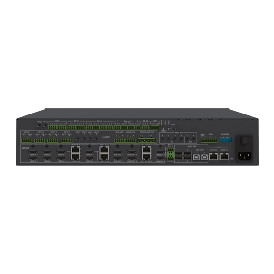
Kramer Electronics Ltd. Figure 3: Connecting to the VS-88UT Rear Panel Connecting the Audio Inputs and Outputs The following are the pinouts for connecting balanced or unbalanced stereo audio sources to the audio inputs: Figure 4: Connecting a Balanced Figure 5: Connecting an Unbalanced Stereo... -
Page 15: Connecting To Vs-88Ut Via
You can connect to the VS-88UT via an RS-232 connection using, for example, a PC. Connect the RS-232 terminal block on the rear panel of the VS-88UT to a PC/controller, as follows (see Figure TX pin to Pin 2 ... -
Page 16: Connecting The Ethernet Port Directly To A Pc
The Local Area Connection Properties window for the selected network adapter appears as shown in Figure Figure 9: Local Area Connection Properties Window 4. Highlight either Internet Protocol Version 6 (TCP/IPv6) or Internet Protocol Version 4 (TCP/IPv4) depending on the requirements of your IT system. VS-88UT - Connecting the VS-88UT... - Page 17 5. Click Properties. The Internet Protocol Properties window relevant to your IT system appears as shown in Figure 10 Figure Figure 10: Internet Protocol Version 4 Properties Window Figure 11: Internet Protocol Version 6 Properties Window VS-88UT - Connecting the VS-88UT...
-
Page 18: Connecting The Ethernet Port Via A Network Hub Or Switch
To control several units via Ethernet, connect the Master unit (Device 1) via the Ethernet port to the Ethernet port of your PC. Use your PC provide initial configuration of the settings (see Connecting VS-88UT via the Ethernet Port on page 13). -
Page 19: Using The Web Pages
VS-88UT via the Ethernet. Before attempting to connect: Perform the procedures in Connecting VS-88UT via the Ethernet Port on page 13. Ensure that your browser is supported. The supported operating systems and Web browsers are specified in the... - Page 20 Figure 15: Routing Settings Page with Navigation List on Left 4. Click the desired Web page or click the arrow to hide the navigation list. Figure 16: Routing Settings Page – Navigation List Hidden VS-88UT - Using the Web Pages...
-
Page 21: Global Mute Feature
REMOTE MUTE was triggered, remain unchanged during the REMOTE MUTE mode and after it ceases. When the REMOTE MUTE mode is over, the system returns to normal operation and the warning note disappears. VS-88UT - Global Mute Feature... -
Page 22: Defining General Settings
Switching when a new signal is detected. Switching in case a cable is unplugged. 5V power off when the signal is lost. Switching when video is lost during a manual override action. VS-88UT - Defining General Settings... - Page 23 1. In the Navigation pane, click Routing Settings. The Routing Matrix page appears. Click Global Settings (on the top left side). The Global Settings window appears. 3. Click Switchable Ports tab. The Switchable Ports tab appears: Figure 19: Global Settings Window – Switchable Ports Tab VS-88UT - Defining General Settings...
- Page 24 3. Click the HDBT Power Support tab. The HDBT Power Support tab appears: Figure 20: Global Settings Window – HDBT Power Support Tab 4. Enable or disable HDBT power support via the HDBT port. 5. Click Close. VS-88UT - Defining General Settings...
-
Page 25: Routing Vs-88Ut Ports
To route an input to an output, click a white routing button within the matrix. For example, to route the HDMI 3 input to the HDMI 1 output, click the routing button connecting them in the matrix: Figure 22: Routing Settings Page – Routing an Input to an Output VS-88UT - Routing VS-88UT Ports... -
Page 26: Defining Port Settings
Setting Analog and Amplified Audio Output Parameters on page 50. Setting and Routing the RS-232 Ports on page 51. Setting and Routing IR Ports on page 52. Setting and Routing the USB Ports on page 53. VS-88UT - Routing VS-88UT Ports... - Page 27 The HDMI port line displays the status of each signal separately. The following example shows that the HDMI 1 input (both audio and video signals) is routed to output HDMI 1 and HDMI 2. Figure 25: Routing Settings Page – HDMI Input Ports VS-88UT - Routing VS-88UT Ports...
- Page 28 To route an input to an output in the breakaway mode: Click on an output (HDMI 3 in this example). The AFV icon is deselected and that output is now in the Breakaway mode. Click beside the HDMI 1 input port name. VS-88UT - Routing VS-88UT Ports...
- Page 29 Figure 29: Routing Settings Page – Routing in the AFV Mode Once you toggle back to (AFV) the audio signal is immediately routed to the HDMI 3 output. Figure 30: Routing Settings Page – Routing in the Breakaway Mode VS-88UT - Routing VS-88UT Ports...
- Page 30 Figure 31: Routing Settings Page – Separate A/V Signal Sources in the Breakaway Mode Once the AFV is back on, the input 2 audio signal follows the video signal. Figure 32: Routing Settings Page – A/V Signal Sources in the AFV Mode VS-88UT - Routing VS-88UT Ports...
- Page 31 Check/uncheck Force 2LPCM. View the Routing Status. Open the AUDIO drop-down box and select the audio signal to follow the HDMI video signal (see Selecting the HDMI Input Follower on page 30). 3. Click Save. VS-88UT - Routing VS-88UT Ports...
- Page 32 Click the HDMI 1 output to see the settings page, and view the routing status: Figure 36: Routing Settings Page – HDMI 1 Output Routing Status The routing status fits the settings on the HDMI 1 input. VS-88UT - Routing VS-88UT Ports...
- Page 33 Figure 38: Routing Settings Page – HDMI 1 Input, Analog Audio 2 Follows In the AFV mode, whenever HDMI 1 is routed to an output the audio source will be ANALOG AUDIO 2: Figure 39: Routing Settings Page – Routing HDMI 1 Routed to Several Outputs VS-88UT - Routing VS-88UT Ports...
- Page 34 Figure 41: Routing Settings Page – HDBT 6 Output Routing Status Click to return to the AFV mode. When routing the HDMI 1 input to HDMI 2 output, the audio source is ANALOG AUDIO 2 once again. VS-88UT - Routing VS-88UT Ports...
- Page 35 Setting the Port to HDBT or HDMI To set the port to HDBT or HDMI: 1. Click next to the port name. 2. Select the desired port: Figure 43: Port Settings – Selecting HDBT or HDMI Input Ports VS-88UT - Routing VS-88UT Ports...
- Page 36 Changing HDMI Input Port Settings on page 29). The following window appears: Figure 45: Routing Settings Page – Input HDBT Settings Each setting retains the switching state (followers are specific for the HDMI and HDBT port). VS-88UT - Routing VS-88UT Ports...
- Page 37 Figure 46: Routing Settings Page – Input HDBT 5 Followers Settings For example, when routing input HDBT 5 to the HDBT 6 output, HDBT 5 audio is routed to the output. Figure 47: Routing Settings Page – Input HDBT 5 Routed to Output HDBT 6 VS-88UT - Routing VS-88UT Ports...
- Page 38 Figure 49: Routing Settings Page – HDBT 6 Input to HDBT 6 Output Routing Status In the following example MIC 1 is set as the audio follower for input HDBT 5: Figure 50: Routing Settings Page – HDBT 5 Input, MIC 1 Audio follows VS-88UT - Routing VS-88UT Ports...
- Page 39 Figure 51: Routing Settings Page –Routing HDBT 5 Input to HDBT 6 Output The HDBT 5 output routing status shows MIC 1 as the source: Figure 52: Routing Settings Page – HDBT 6 Output Routing Status VS-88UT - Routing VS-88UT Ports...
- Page 40 Figure 54: Routing Settings Page – HDBT 5 Output in the Breakaway Mode Click to return to the AFV mode. When routing the HDBT 5 input to HDBT 5 output, the audio source is MIC 1 once again. VS-88UT - Routing VS-88UT Ports...
- Page 41 40. Changing the Analog Audio Port Settings on page 41. Setting the Port to Analog Input or Two Microphones on page 41. Changing the Microphone Port Settings on page 43. VS-88UT - Routing VS-88UT Ports...
- Page 42 To set the input volume: 1. Click The volume slider window appears. 2. Set the volume (set to 0dB by default). Figure 56: Port Settings –Setting Analog Audio Level 3. If required, click to mute the input. VS-88UT - Routing VS-88UT Ports...
- Page 43 To set a port to function as an analog input or as two microphone inputs: 1. Click next to the port name. 2. Set ANALOG AUDIO 1 (for example) to MIC 1 MIC 2 desired port. Figure 58: Port Settings – Selecting Analog Audio or Mic Input Ports VS-88UT - Routing VS-88UT Ports...
- Page 44 To set a MIC port to function as an analog input: 1. Click next to one of the MIC ports. 2. Set MIC 1 (for example) to ANALOG AUDIO 1. Figure 60: Port Settings – Selecting MIC to ANALOG AUDIO VS-88UT - Routing VS-88UT Ports...
- Page 45 Figure 61: Port Settings – Setting MIC Ports Changing the Microphone Port Settings To change the MIC Port settings: 1. Click MIC. The following window appears: Figure 62: Routing Settings Page – Input MIC Settings VS-88UT - Routing VS-88UT Ports...
- Page 46 Turn HDMI on or off ( Mute or unmute the audio signal ( The following functions are available: Changing the HDMI Output Port Settings on page 45. Changing the HDBT Output Port Settings on page 47. VS-88UT - Routing VS-88UT Ports...
- Page 47 Kramer Electronics Ltd. Changing the HDMI Output Port Settings To set the HDMI output port: 1. Click HDMI. The following window appears: Figure 64: Routing Settings Page – Output HDMI Settings VS-88UT - Routing VS-88UT Ports...
- Page 48 View the Routing Status. Select a Video Pattern. Open the Auto Switching drop-down box and select Manual, Priority or Last Connected switching, see Auto Switching Feature on page 48. 3. Click Save. VS-88UT - Routing VS-88UT Ports...
- Page 49 Kramer Electronics Ltd. Changing the HDBT Output Port Settings To set the HDBT output port: 1. Click HDBT. The following window appears: Figure 65: Routing Settings Page – HDBT Output Settings VS-88UT - Routing VS-88UT Ports...
- Page 50 2. If Auto Switching is set to Priority or Last Connected, you can do the following: Drag and drop an input to set the priority order: Figure 66: Routing Settings Page –Priority Setup Delete input/s to exclude them from the priority list. VS-88UT - Routing VS-88UT Ports...
- Page 51 The priority order numbers appear under output HDBT 6. Last Connected (LC) appears under outputs HDMI 3 and HDBT 5 (where input HDMI 3 was removed from the Last Connected list) Figure 68: Routing Settings Page – Using Auto Switching VS-88UT - Routing VS-88UT Ports...
- Page 52 Figure 69: Port Settings – Audio Outputs To set an audio output: 1. Click the audio icon ( 2. Use the slider to set the audio volume, or click the below to mute the audio output. Figure 70: Audio Settings VS-88UT - Routing VS-88UT Ports...
- Page 53 Click RS-232 1 on input or output to view the RS-232 routing status and change the port label (see also Changing HDMI Input Port Settings on page Changing the HDBT Output Port Settings on page 47). VS-88UT - Routing VS-88UT Ports...
- Page 54 IR signals (5 and 6) via HDBT outputs 5 and 6, respectively. Click IR inputs or outputs to view the IR routing status and change the port label (see also Changing HDMI Input Port Settings on page Changing the HDBT Output Port Settings on page 47). VS-88UT - Routing VS-88UT Ports...
- Page 55 Click USB Type B on inputs or USB Type A on outputs to view the USB routing status and change the port label (see also Changing HDMI Input Port Settings on page Changing the HDBT Output Port Settings on page 47). VS-88UT - Routing VS-88UT Ports...
-
Page 56: Controlling Devices Via The Controller
Click here to download K-Config 3. Create a room controller configuration via K-Config 3 and then sync the configuration to the device (see Room Controller Configuration via K-Config 3 on page 55). VS-88UT - Controlling Devices via the Controller... -
Page 57: Room Controller Configuration Via K-Config 3
Figure 75: Controller Page – Select Master Device via K-CONFIG 2. Click OK. VS-88UT-RC is added as the Master controller with all its physical ports and virtual Ethernet ports. 3. Configure the ports and add peripheral devices, commands and macros as needed. - Page 58 The following message appears: Figure 77: Controller Page – Login 8. Type-in the VS-88UT webpage password for ADMIN (Admin, by-default). 9. Click Login. K-CONFIG status displays Online. 10. Click Sync to Device. The following message appears: VS-88UT - Controlling Devices via the Controller...
-
Page 59: Controlling Devices
Controller page once the configuration is uploaded. The device menu enables: Controlling a Peripheral Device on page 58. Controlling an Auxiliary Device on page 60. Controlling a Virtual Device on page 61. VS-88UT - Controlling Devices via the Controller... - Page 60 1. In the Controller page, click Devices. The Device menu appears: Figure 80: Controller Page – Device Menu In this example, the Device menu list shows the room controller section (VS-88UT-RC), an auxiliary device (Kramer RC-74DL) and a virtual device. 2. Click next to VS-88UT-RC to view the devices connected to the room controller: Figure 81: Controller Page –...
- Page 61 Figure 83: Controller Page –Peripheral Device Available Commands The list of all the configured commands appears on the right-side of the page. 5. Click a command button. The selected command is performed on the peripheral device. VS-88UT - Controlling Devices via the Controller...
- Page 62 2. Click an Auxiliary device (RC-74DL). The Device menu appears: Figure 84: Controller Page – Controlling an Auxiliary Device 3. Click a room-controller device-button. The action list (as defined by K-Config 3) is performed. VS-88UT - Controlling Devices via the Controller...
- Page 63 3) is performed. 4. If desired, click the blue arrow next to the virtual device for a full-page view (enables a clearer view when the virtual device includes several sets of device controllers). VS-88UT - Controlling Devices via the Controller...
-
Page 64: Activating Macros
1. In the Controller page click Macros. The Macros window appears: Figure 86: Controller Page – Macros Window 2. Click All On or All Off as required. VS-88UT - Controlling Devices via the Controller... -
Page 65: Scheduling Macros
1. In the Controller page click Scheduled Tasks. The Scheduled Tasks window appears: Figure 87: Controller Page – Scheduled Tasks 2. Hover over a day and time Figure 88: Controller Page – Selecting a Day and Time VS-88UT - Controlling Devices via the Controller... - Page 66 Figure 89: Controller Page – Adding a Scheduled Task 4. Select a Macro (All On or All Off), set the exact activation time and click Add. The scheduled macro appears in the table: Figure 90: Controller Page – Scheduled Task Added VS-88UT - Controlling Devices via the Controller...
-
Page 67: Setting The Date And Time
From a server address by clicking the IP address of the clock source, the time zone and checking DST if you are on Daylight Saving Time. Figure 91: Controller Page – Date and Time Settings VS-88UT - Controlling Devices via the Controller... -
Page 68: Managing Edid
View the currently selected EDID source Bytemap by clicking Bytemap on the right side. To copy an EDID from an output to an input: 1. In the Navigation pane, click EDID. The EDID Management page appears. Figure 92: EDID Management Page VS-88UT - Managing EDID... - Page 69 2. Select the EDID source (for example, one of the inputs). If you are reading EDID from an output, make sure that that output is connected to an acceptor. Figure 93: EDID Management Page – Select an EDID Input (Read From) VS-88UT - Managing EDID...
- Page 70 3. Select the input/s (or all the inputs) to which the EDID is copied. Figure 94: EDID Management Page – Select the Inputs (Copy To) 4. Click COPY. The Input 2 EDID is copied to the selected inputs. Figure 95: EDID Page – EDID Copied VS-88UT - Managing EDID...
- Page 71 1. In the Navigation pane, click EDID. The EDID Management page appears. 2. In the File area click …. 3. Select the EDID file. 4. Select the input/s (or all the inputs) to which the EDID is copied. 5. Click Copy and follow the instructions on-screen. VS-88UT - Managing EDID...
-
Page 72: Changing The Device Settings
Performing Firmware Upgrade on page 71. Setting Authentication on page 72. Resetting to Factory Default Parameters 1. In the Navigation pane, click Device Settings. The Device Settings page appears: Figure 97: Device Settings Page VS-88UT - Changing the Device Settings... -
Page 73: Performing Firmware Upgrade
Figure 99: Device Settings Page – Firmware Upgrade Message 3. Click OK. Wait for completion of the upgrade process: Figure 100: Device Settings Page – Firmware Upgrade Process 4. Wait for the device to restart. VS-88UT - Changing the Device Settings... -
Page 74: Setting Authentication
The following message appears: Figure 101: Password Settings Page – Disabling Authentication 2. Type the password and click Save. The device settings page no longer shows the authentication details: Figure 102: Password Settings Page –Security Deactivated VS-88UT - Changing the Device Settings... - Page 75 2. Click Ok, and add the password details. Figure 104: Password Settings Page – Security Activation Message 3. Click Save. The following message appears: Figure 105: Password Settings Page – Password Updated 4. Click OK. VS-88UT - Changing the Device Settings...
-
Page 76: Setting Network Parameters
After changing the IP address, reload the Web page with the new IP address. After changing the Subnet mask, power cycle the VS-88UT. If DHCP is checked, reload the Web page with the new IP address (see below). - Page 77 Figure 107: Network Settings Page 5. Click Yes. 6. Type the device name in the address bar of your browser to reload the page. You can read the new IP address from the Network Settings page. VS-88UT - Setting Network Parameters...
-
Page 78: Viewing The About Page
Kramer Electronics Ltd. Viewing the About Page VS-88UT About page lets you view the Web page version and Kramer Electronics Ltd details. Figure 108: About Page VS-88UT - Viewing the About Page... -
Page 79: Technical Specifications
Connector for programming services Extension Reach 4K @60Hz (4:2:0) Up to 100m (330ft) Full HD (1080p @60Hz 36bpp) Up to 130m (430ft) HDBaseT Ultra Mode and Full Up to 180m (590ft) HD (1080p @60Hz 24bpp) Compliance HDBaseT 2.0 VS-88UT - Technical Specifications... - Page 80 Shipping Weight 2.75kg (6.1lbs) approx. Accessories Included Power cord Optional For optimum range and performance use the recommended USB, Ethernet, serial and IR Kramer cables available at www.kramerav.com/product/VS-88UT Specifications are subject to change without notice at www.kramerav.com VS-88UT - Technical Specifications...
-
Page 81: Default Communication Parameters
Maximum TCP Connections: 70 (Web client not connected) TCP Port #: 5000 Maximum TCP Connections: 10 (Web client connected) Full Factory Reset Use “#FACTORY” command and use “#RESET” to restore the factory default Protocol 3000 values. VS-88UT - Technical Specifications... -
Page 82: Protocol 3000
You can enter commands directly using terminal communication software (e.g., Hercules) by connecting a PC to the serial or Ethernet port on the VS-88UT. To enter CR press the Enter key (LF is also sent but is ignored by the command parser). -
Page 83: Understanding Protocol 3000
A separate response is sent for every command in the chain. Kramer Protocol 3000 Syntax The Kramer Protocol 3000 syntax uses the following delimiters: CR = Carriage return (ASCII 13 = 0x0D) ... -
Page 84: Extended Protocol 3000
Command SP[Param1 ,Param2 …] result Extended Protocol 3000 In addition to the standard Protocol 3000 syntax, newer Kramer products use extended syntax to improve user experience and provide easier deployment and configuration. For products with many ports and of different types, the extended syntax describes commands and their parameters in a more intuitive, user-friendly format. - Page 85 OUT.HDMI.4 (refers to HDMI output port 4) BOTH.RS232.2 (refers to bidirectional RS-232 port 2) Direction Types The string representation is not case sensitive. String Meaning Input port Output port BOTH Bi-directional port where the direction has no meaning VS-88UT - Protocol 3000...
- Page 86 Data signal of the port (relevant for HDBT and RS-232 ports for example) IR signal of the port (relevant for HDBT and IR ports for example) USB signal of the port (relevant for HDBT and USB_A/B ports for example) VS-88UT - Protocol 3000...
-
Page 87: Other Rules
Brackets ‘[‘ and ‘]’ are reserved Protocol 3000 characters that define a list of parameters as in [a,b,c,d]. Example: to route video input 3 to outputs 1,4,6,7: ROUTE 1,[1,4,6,7],3<cr> Example illustrating brackets and commas: #SIGNALS-LIST? ~01@SIGNALS-LIST [IN.SDI.1.VIDEO.1,IN.SDI.2.VIDEO.1,IN.SDI.3.VIDEO.1,IN.SDI.4.VIDEO.1,IN.SDI. 5.VIDEO.1,IN.SDI.6.VIDEO.1,IN.SDI.7.VIDEO.1,IN.SDI.8.VIDEO.1,OUT.SDI.1.VIDEO .1,OUT.SDI.2.VIDEO.1,OUT.SDI.3.VIDEO.1,OUT.SDI.4.VIDEO.1,OUT.SDI.5.VIDEO.1,O UT.SDI.6.VIDEO.1,OUT.SDI.7.VIDEO.1,OUT.SDI.8.VIDEO.1] VS-88UT - Protocol 3000... -
Page 88: Protocol 3000 Commands
Description Syntax Set: Protocol handshaking Get: Response ~nn@SPOKCR LF Notes Validates the Protocol 3000 connection and gets the machine number. Step-in master products use this command to identify the availability of a device. K-Config Example “#”,0x0D VS-88UT - Protocol 3000... - Page 89 Get command list or help for specific #HELPCR Get: command Response Multi-line: ~nn@Device available protocol 3000 commands:CR LFcommand,SP command...CR LF Parameters COMMAND_NAME – name of a specific command Notes To get help for a specific command use: HELPSPCOMMAND_NAMECR LF K-Config Example “#HELP”,0x0D VS-88UT - Protocol 3000...
- Page 90 To avoid locking the port due to a USB bug in Windows, disconnect USB connections immediately after running this command. If the port was locked, disconnect and reconnect the cable to reopen the port. K-Config Example “#RESET”,0x0D VS-88UT - Protocol 3000...
- Page 91 The machine name is not the same as the model name. The machine name is used to identify a specific machine or a network in use (with DNS feature on). K-Config Example Set the DNS name of the device to “room-442”: “#NAME room-442”,0x0D VS-88UT - Protocol 3000...
-
Page 92: System Commands
After execution, a response is sent to the com port from which the Get was received A response is sent after every change in input signal status from On to Off or from Off to On K-Config Example Get the input signal lock status of IN 1: “#SIGNAL? 1”,0x0D VS-88UT - Protocol 3000... - Page 93 – 1 (Maestro), 1 (room controller) enable – 0 (disable), 1 (enable) Notes This command is designed to be used by machines and not by users. K-Config Example Get the room controller feature state (for the room controller): “#FEATURE-LIST? 1”,0x0D VS-88UT - Protocol 3000...
- Page 94 Port ID Format on page for further information. label_text – ASCII characters without space Notes Labels are used commonly by WEB pages Examples #X-LABEL OUT.HDMI.5,LG-28D ~01@X-LABEL OUT.HDMI.5,LG-28D K-Config Example Set the port label (for input 1): “#X-LABEL IN.HDMI.1,DVD”,0x0D VS-88UT - Protocol 3000...
- Page 95 User may query group names using the command: #X-PORT-SELECT-LIST? This command is designed to be used by machines and not by users. This command is used for feature auto-discovery mechanism. Example #x-port-select? IN.AUDIO.1 ~01@X-PORT-SELECT IN.AUDIO.1,0,[0:[IN.ANALOG_AUDIO.1],1:[IN.MIC.1,IN.MIC.2]] #x-port-select? IN.VIDEO.5 ~01@X-PORT-SELECT IN.VIDEO.5,1,[0:[IN.HDMI.5],1:[IN.HDBT.5]] VS-88UT - Protocol 3000...
- Page 96 SINK supports HDCP (and not if the actual signal is HDCP protected) and just in case a signal is sent to the output. In case no Signal is routed to this specific output the status could be inaccurate or missing at all. K-Config Example Get the output HDCP-STATUS of IN 1: “#HDCP-STAT? 0,1”,0x0D VS-88UT - Protocol 3000...
- Page 97 The response is returned in one line and terminated with CR LF The response format lists port IDs separated by commas. Examples #PORTS-LIST? ~01@PORTS-LIST [IN.HDMI.1,IN.HDMI.2,IN.HDMI.3,IN.HDMI.4,IN.HDMI.5,IN.HDBT.5,IN.HDMI.6,IN.HDBT.6 ,…, OUT.HDMI.1,OUT.HDMI.2,…,IN.ANALOG_AUDIO.1,IN.ANALOG_AUDIO.2,…, IN.MIC.6,IN.MIC.7,IN.MIC.8,BOTH.RS232.1] K-Config Example Get the ports list: “#PORTS-LIST?”,0x0D VS-88UT - Protocol 3000...
- Page 98 The response is returned in one line and terminated with ␍␊ The response format lists signal IDs separated by commas. Examples #SIGNALS-LIST? ~01@SIGNALS-LIST [IN.HDMI.1.VIDEO.1,IN.HDMI.2.VIDEO.1,IN.HDMI.3.VIDEO.1,…,IN.HDBT.5.VIDEO.1,IN.HD BT.6.VIDEO.1,…,OUT.HDMI.1.VIDEO.1,…,IN.ANALOG_AUDIO.1.AUDIO.1,…, IN.MIC.1.AUDIO.1,IN.MIC.2.AUDIO.1,…,IN.HDMI.1.AUDIO.1,IN.HDMI.2.AUDIO.1,…, IN.HDBT.6.AUDIO.1,IN.HDBT.7.AUDIO.1,…,OUT.HDMI.1.AUDIO.1,…,IN.HDBT.5.RS232.1, IN.HDBT.6.RS232.1,…,OUT.HDBT.5.RS232.1,OUT.HDBT.6.RS232.1,BOTH.RS232.1.RS232.1, …,IN.HDBT.5.IR.1,IN.HDBT.6.IR.1,IN.HDBT.7.IR.1,…,OUT.HDBT.6.IR.1,OUT.IR.5.IR.1, …,IN.HDBT.5.USB.1,IN.HDBT.6.USB.1,…,OUT.HDBT.6.USB.1,BOTH.USB_A.1.USB.1,BOTH.USB _A.2.USB.1,BOTH.USB_B.1.USB.1,BOTH.USB_B.2.USB.1] K-Config Example Get signal ID list: “#SIGNALS-LIST?”,0x0D VS-88UT - Protocol 3000...
- Page 99 – level of login to set: User, Admin password – password for the login_level. Up to 15 printable ASCII chars. Notes The default password is an empty string. K-Config Example Set the password for the Admin protocol permission level to 33333: “#PASS Admin,33333”,0x0D VS-88UT - Protocol 3000...
- Page 100 Kramer Electronics Ltd. EDID Handling Commands Additional EDID data functions can be performed via a compatible EDID management application, such as Kramer EDID Designer (see www.kramerav.com/product/EDID%20Designer). Command Description CPEDID Copy EDID data from the output to the input EEPROM EDID-AUDIO...
- Page 101 ColSpace – color space: 0 (RGB), 1 (YCbCr 4:2:2), 2 (YCbCr 4:4:4), 3 (All), 4 (Automatic/original config) Notes Set command might change the current EDID K-Config Example Set HDMI IN 3 EDID color space to RGB (enabled): “#EDID-CS IN.HDMI.3.AUDIO.1,0”,0x0D VS-88UT - Protocol 3000...
- Page 102 After every change in output HPD status from Off to On (1) After every change in output HPD status form Off to On and all parameters (new EDID, etc.) are stable and valid (2) K-Config Example Get the output HPD status of Output 1: “#DISPLAY? 1”,0x0D VS-88UT - Protocol 3000...
-
Page 103: Routing Commands
This command is designed to be used by machines and not by users. This command is used for the auto-discovery mechanism feature. Example #MATRIX-STATUS? ~01@MATRIX-STATUS [[IN.HDBT.5.RS232.1,OUT.HDBT.5.RS232.1],[IN.HDBT.5.IR.1,IN.IR.5.IR.1],[IN.HDBT.6 .RS232.1,OUT.HDBT.6.RS232.1],[IN.HDBT.6.IR.1,IN.IR.6.IR.1],[IN.HDBT.7.RS232.1,BO TH.RS232.1.RS232.1],[IN.HDBT.7.IR.1,IN.IR.7.IR.1],[IN.HDBT.8.IR.1,IN.IR.8.IR.1], [OUT.HDMI.1.VIDEO.1,IN.HDBT.6.VIDEO.1],[OUT.HDMI.1.AUDIO.1,IN.HDBT.6.AUDIO.1], …,[OUT.AMPLIFIED_AUDIO.1.AUDIO.1,IN.ANALOG_AUDIO.2.AUDIO.1],[OUT.HDBT.6.RS232.1, IN.HDBT.6.RS232.1],[OUT.HDBT.6.IR.1,OUT.IR.6.IR.1],[OUT.HDBT.6.USB.1,IN.HDBT.6.U SB.1],[BOTH.USB_A.2.USB.1,BOTH.USB_B.2.USB.1],[BOTH.USB_A.1.USB.1,BOTH.USB_B.1.U SB.1]] K-Config Example Get the room controller current matrix state: “#MATRIX-STATUS?”,0x0D VS-88UT - Protocol 3000... - Page 104 Get: ~nn@X-AUD-LVL-RANGESPanalog_output_id, audio_level_rangeCR LF Parameters analog_output_id – analog output signal ID: see Signal ID Format on page Example #X-AUD-LVL-RANGE? OUT.ANALOG_AUDIO.1.AUDIO.1 ~01@ X-AUD-LVL-RANGE? OUT.ANALOG_AUDIO.1.AUDIO.1, [-83,24] K-Config Example get the analog output 3 audio level range: “#X-AUD-LVL-RANGE? OUT.ANALOG_AUDIO.3.AUDIO.1”,0x0D VS-88UT - Protocol 3000...
- Page 105 Could be audio, video and maybe IR, USB or data if this capability is supported by the product. Example #x-mute OUT.HDMI.1.VIDEO.1,ON ~01@X-MUTE OUT.HDMI.1.VIDEO.1,ON #x-mute? OUT.HDMI.1.VIDEO.1 ~01@X-MUTE OUT.HDMI.1.VIDEO.1,ON #x-mute OUT.ANALOG_AUDIO.1.AUDIO.1,OFF ~01@X-MUTE OUT.ANALOG_AUDIO.1.AUDIO.1,OFF #x-mute? OUT.ANALOG_AUDIO.1.AUDIO.1 ~01@X-MUTE OUT.ANALOG_AUDIO.1.AUDIO.1,OFF K-Config Example Mute the video on HDMI OUT 4: “#X-MUTE OUT.HDMI.4.VIDEO.1,ON”,0x0D VS-88UT - Protocol 3000...
- Page 106 ~01@X-PRIORITY OUT.HDMI.7.VIDEO.1, [IN.HDMI.1.VIDEO.1,IN.HDMI.2.VIDEO.1,IN.HDMI.3.VIDEO.1] K-Config Example Set the input priority for HDMI OUT 3 (in this order – HDMI IN 2 first priority followed by HDMI IN 3 and HDMI IN 1): “#X-PRIORITY OUT.HDMI.3.VIDEO.1, [IN.HDMI.2.VIDEO.1, IN.HDMI.3.VIDEO.1, IN.HDMI.1.VIDEO.1]”,0x0D VS-88UT - Protocol 3000...
- Page 107 Video 1 is the default port in this command and is implied even if not written: #X-ROUTE OUT.HDMI.5,IN.HDMI.1 is interpreted as: #X-ROUTE OUT.HDMI.5.VIDEO.1,IN.HDMI.1.VIDEO.1 Examples #X-ROUTE OUT.HDMI.5.VIDEO.1,IN.HDMI.1.VIDEO.1 ~01@X-ROUTE OUT.HDMI.5.VIDEO.1,IN.HDMI.1.VIDEO.1 #X-ROUTE? OUT.HDMI.5.VIDEO.1 ~01@X-ROUTE OUT.HDMI.5.VIDEO.1,IN.HDMI.1.VIDEO.1 Reduced form : #X-ROUTE OUT.HDMI.5,IN.HDMI.1 ~01@X-ROUTE OUT.HDMI.5.VIDEO.1,IN.HDMI.1.VIDEO.1 K-Config Example Route HDMI IN 2 to HDMI OUT 3: “#X-ROUTE OUT.HDMI.3.VIDEO.1,IN.HDMI.2.VIDEO.1”,0x0D VS-88UT - Protocol 3000...
- Page 108 – audio level in dB (range between -60 to +30) depending of the ability of the product Example #X-AUD-LVL OUT.ANALOG_AUDIO.1.AUDIO.1,-10 ~01@X-AUD-LVL OUT.ANALOG_AUDIO.1.AUDIO.1,-10 #X-AUD-LVL? OUT.ANALOG_AUDIO.1.AUDIO.1 ~01@X-AUD-LVL OUT.ANALOG_AUDIO.1.AUDIO.1,-10.00 K-Config Example Set analog audio output 2 level to +15: “#X-AUD-LVL OUT.ANALOG_AUDIO.2.AUDIO.1,15”,0x0D VS-88UT - Protocol 3000...
- Page 109 Parameters signal_id – see Signal ID Format on page mode – OFF/ON (not case sensitive) Example #X-AUD-ONLY OUT.HDMI.2.VIDEO.1,ON ~01@X-AUD-ONLY OUT.HDMI.2.VIDEO.1,ON #X-AUD-ONLY? OUT.HDMI.2.VIDEO.1 ~01@X-AUD-ONLY OUT.HDMI.2.VIDEO.1,ON K-Config Example Set HDMI OUT 3 to audio only: “#FEATURE LIST OUT.HDMI.3.VIDEO.1,ON”,0x0D VS-88UT - Protocol 3000...
- Page 110 Some devices support extra range (long reach) mode, used in HDBT applications. Use the command #PORTS-LIST? to list all port IDs available in the system Example #X-LONG-REACH IN.HDBT.1,OFF ~01@X-LONG-REACH IN.HDBT.1,OFF #X-LONG-REACH? IN.HDBT.1 ~01@X-LONG-REACH IN.HDBT.1,OFF K-Config Example Set extra range for HDBT IN 7: “#X-LONG-REACH IN.HDBT.7,On”,0x0D VS-88UT - Protocol 3000...
- Page 111 This command is designed to enable patterns (audio and video) on any signal. Pattern numbers vary according to the signal type. Example #X-PATTERN OUT.HDMI.1.VIDEO.1,1 ~01@X-PATTERN OUT.HDMI.1.VIDEO.1,1 #X-PATTERN OUT.ANALOG_AUDIO.1.AUDIO.1,1 ~01@X-PATTERN OUT.ANALOG_AUDIO.1.AUDIO.1,1 #X-PATTERN? OUT.ANALOG_AUDIO.1.AUDIO.1 ~01@X-PATTERN OUT.ANALOG_AUDIO.1.AUDIO.1,1 K-Config Example Set video pattern 3 on HDMI OUT 8 (enabled): “#X-PATTERN OUT.HDMI.8.VIDEO.1,3”,0x0D VS-88UT - Protocol 3000...
- Page 112 This syntax uses the new convention of using brackets to define a list of fields “[ ]” Example #X-SET-FOLLOWERS IN.HDMI.2.VIDEO.1,[IN.HDMI.1.AUDIO.1] ~01@X-SET-FOLLOWERS IN.HDMI.2.VIDEO.1,[IN.HDMI.1.AUDIO.1] #X-SET-FOLLOWERS? IN.HDMI.2.VIDEO.1 ~01@X-SET-FOLLOWERS IN.HDMI.2.VIDEO.1,[IN.HDMI.1.AUDIO.1] K-Config Example Set HDMI 1 audio signal and HDBT 7 IR signal to follow HDBT IN 7: “#X-SET-FOLLOWERS IN.HDBT.7.VIDEO.1,[IN.HDMI.1.AUDIO.1,IN.HDBT.7.IR.1]”,0x0D VS-88UT - Protocol 3000...
- Page 113 0.5 sec in order to trigger a global system mute. Example ->Trigger Happen ~01@GLOBAL-MUTE ON ->Trigger Happen ~01@GLOBAL-MUTE OFF #GLOBAL-MUTE ON ~01@GLOBAL-MUTE ON #GLOBAL-MUTE OFF ~01@GLOBAL-MUTE OFF K-Config Example Get Remote Mute state: “#GLOBAL-MUTE?”,0x0D “#GLOBAL-MUTE ON”,0x0D VS-88UT - Protocol 3000...
- Page 114 NAME command. You can also get an assigned IP by direct connection to USB or RS-232 protocol port if available. Consult your network administrator for correct settings. K-Config Example Enable DHCP mode, if available: “#NET-DHCP 1”,0x0D VS-88UT - Protocol 3000...
- Page 115 Functions Permission Transparency Set: NET-MAC? Get: End User Public Description Syntax Set: #NET-MAC?CR Get: Get MAC address Response ~nn@NET-MACSPmac_addressCR LF Parameters mac_address – unique MAC address. Format: XX-XX-XX-XX-XX-XX where X is hex digit K-Config Example “#NET-MAC?”,0x0D VS-88UT - Protocol 3000...
- Page 116 Get a network configuration. Response Get: ~nn@NET-CONFIGSPid,ip,net_mask,gatewayCR LF Parameters id – network ID ip – network IP net_mask – network mask gateway – network gateway Example # NET-CONFIG 1,192.168.113.10,255.255.0.0,192.168.0.1 ~01@ NET-CONFIG 1,192.168.113.10,255.255.0.0,192.168.0.1 K-Config Example Get network configuration: “#NET-CONFIG?”,0x0D VS-88UT - Protocol 3000...
- Page 117 There is no “Set” command. Use NET-CONFIG to setup network, including DNS name servers. If dns_id is out of the defined DNS range, Err=03 is returned. If no dns_id is defined, Err 03 is returned for any dns_id. K-Config Example Get DNS name server: “#NET-DNS?”,0x0D VS-88UT - Protocol 3000...
- Page 118 What Kramer Electronics Will Do Kramer Electronics will, at its sole option, provide one of the following three remedies to whatever extent it shall deem necessary to satisfy a proper claim under this limited warranty: Elect to repair or facilitate the repair of any defective parts within a reasonable period of time, free of any charge for the necessary parts and labor to complete the repair and restore this product to its proper operating condition.
- Page 119 SAFETY WARNING Disconnect the unit from the power supply before opening and servicing For the latest information on our products and a list of Kramer distributors, visit our Web site where updates to this user manual may be found. We welcome your questions, comments, and feedback.
Need help?
Do you have a question about the VS-88UT and is the answer not in the manual?
Questions and answers