Table of Contents
Advertisement
Quick Links
Kramer Electronics, Ltd.
USER MANUAL
Models:
VP-88ETH,
VP-84ETH,
VP-82ETH,
VP-66ETH,
VP-64ETH,
8x8 RGBH / Balanced Audio Matrix Switcher
8x4 RGBH / Balanced Audio Matrix Switcher
8x2 RGBH / Balanced Audio Matrix Switcher
6x6 RGBH / Balanced Audio Matrix Switcher
6x4 RGBH / Balanced Audio Matrix Switcher
Advertisement
Table of Contents

Related Manuals for Kramer VP-88ETH


Summary of Contents for Kramer VP-88ETH
- Page 1 Kramer Electronics, Ltd. USER MANUAL Models: VP-88ETH, 8x8 RGBH / Balanced Audio Matrix Switcher VP-84ETH, 8x4 RGBH / Balanced Audio Matrix Switcher VP-82ETH, 8x2 RGBH / Balanced Audio Matrix Switcher VP-66ETH, 6x6 RGBH / Balanced Audio Matrix Switcher VP-64ETH, 6x4 RGBH / Balanced Audio Matrix Switcher...
-
Page 2: Table Of Contents
Using the TERM: 75 /TTL Buttons Controlling Several RGBHV / Balanced Audio Matrix Switchers Control Configuration via RS-232 and RS-485 Control Configuration via RS-485 Control Configuration via the ETHERNET Port Technical Specifications Table of Hex Codes for the Master VP-88ETH Communication Protocol... - Page 3 Figure 4: VP-66ETH 6x6 RGBHV / Balanced Audio Matrix Switcher Figure 5: VP-64ETH 6x4 RGBHV / Balanced Audio Matrix Switcher Figure 6: Connecting the VP-88ETH 8x8 RGBHV / Balanced Audio Matrix Switcher Figure 7: Connecting the Balanced Stereo Audio Input/Output...
-
Page 4: Introduction
GROUP 6: Accessories and Rack Adapters; GROUP 7: Scan Converters and Scalers; and GROUP 8: Cables and Connectors 2 Available in the following models: VP-88ETH (an 8x8 model), VP-84ETH (an 8x4 model), VP-82ETH (an 8x2 model), VP-66ETH (a 6x6 model), and/or VP-64ETH (a 6x4 model) 3 Downloadable from our Web site at http://www.kramerelectronics.com... -
Page 5: Overview
RS-485 or RS-232 serial commands transmitted by a touch screen system, PC, or other serial controller ETHERNET The Kramer RC-IR1 Infra-Red Remote Control Transmitter The VP-88ETH/VP-84ETH/VP-82ETH/VP-66ETH/VP-64ETH is dependable, rugged and fits into three vertical spaces (3U) of a standard 19"... -
Page 6: Your Rgbh / Balanced Audio Matrix Switcher
Kramer VP-88ETH/VP-84ETH/VP-82ETH/VP-66ETH/ VP-64ETH away from moisture, excessive sunlight and dust Your RGBH / Balanced Audio Matrix Switcher This section describes each switcher as follows: VP-88ETH (see Figure 1) VP-84ETH (see Figure 2) VP-82ETH (see Figure 3) VP-66ETH (see Figure 4) VP-64ETH (see Figure 5) Table 1 and Table 2 define the front and rear panels of the machines. -
Page 7: Figure 1: Vp-88Eth 8X8 Rgbhv / Balanced Audio Matrix Switcher
Your RGBH / Balanced Audio Matrix Switcher Figure 1: VP-88ETH 8x8 RGBHV / Balanced Audio Matrix Switcher KRAMER: SIMPLE CREATIVE TECHNOLOGY... -
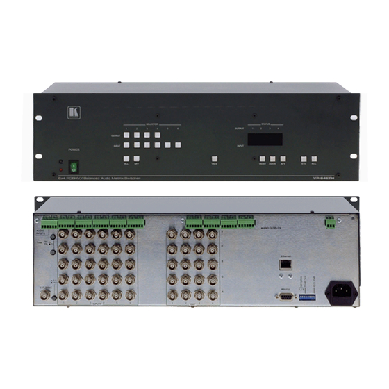
Page 8: Figure 2: Vp-84Eth 8X4 Rgbhv / Balanced Audio Matrix Switcher
Your RGBH / Balanced Audio Matrix Switcher Figure 2: VP-84ETH 8x4 RGBHV / Balanced Audio Matrix Switcher... -
Page 9: Figure 3: Vp-82Eth 8X2 Rgbhv / Balanced Audio Matrix Switcher
Your RGBH / Balanced Audio Matrix Switcher Figure 3: VP-82ETH 8x2 RGBHV / Balanced Audio Matrix Switcher KRAMER: SIMPLE CREATIVE TECHNOLOGY... -
Page 10: Figure 4: Vp-66Eth 6X6 Rgbhv / Balanced Audio Matrix Switcher
Your RGBH / Balanced Audio Matrix Switcher Figure 4: VP-66ETH 6x6 RGBHV / Balanced Audio Matrix Switcher... -
Page 11: Figure 5: Vp-64Eth 6X4 Rgbhv / Balanced Audio Matrix Switcher
Your RGBH / Balanced Audio Matrix Switcher Figure 5: VP-64ETH 6x4 RGBHV / Balanced Audio Matrix Switcher KRAMER: SIMPLE CREATIVE TECHNOLOGY... -
Page 12: Table 1: The Rgbh / Balanced Audio Matrix Switcher Front Panel Features
Table 1: The RGBH / Balanced Audio Matrix Switcher Front Panel Features Feature Function IR Receiver The red LED is illuminated when receiving signals from the Kramer Infra- Red remote control transmitter POWER switch Illuminated switch for turning the unit ON or OFF... -
Page 13: Table 2: The Rgbh / Balanced Audio Matrix Switcher Rear Panel Features
Connects to the external sync source 1 VP-88ETH has 8 inputs and 8 outputs; VP-84ETH has 8 inputs and 4 outputs; VP-82ETH has 8 inputs and 2 outputs; VP-66ETH has 6 inputs and 6 outputs; VP-64ETH has 6 inputs and 4 outputs 2 The ground connection is sometimes connected to the shield of the RS-485 cable. -
Page 14: Connecting The Rgbh / Balanced Audio Matrix Switcher
“Y” and the Green for “C”) then the output channels should be used similarly (Red for “Y” and Green for “C”) 1 Switch off the power on each device before connecting it to your VP-88ETH. After connecting your VP-88ETH, switch on its power and then switch on the power on each device... -
Page 15: Figure 6: Connecting The Vp-88Eth 8X8 Rgbhv / Balanced Audio Matrix Switcher
Connecting the RGBH / Balanced Audio Matrix Switcher Audio Connections are not shown RGBHV High Resolution Graphics Source 1 RS-232 RGBHV RGBHV Projector Display RGBHV High Resolution Graphics Source 6 Figure 6: Connecting the VP-88ETH 8x8 RGBHV / Balanced Audio Matrix Switcher KRAMER: SIMPLE CREATIVE TECHNOLOGY... -
Page 16: Connecting The Balanced/Unbalanced Stereo Audio Input/Output
A balanced input/output connection (see Figure 7) An unbalanced audio input (see Figure 8) An unbalanced source to the balanced input on the VP-88ETH (see Figure 9) Figure 7 illustrates how to wire a balanced input/output connection: Figure 7: Connecting the Balanced Stereo Audio Input/Output... -
Page 17: Controlling Via Rs-232 (For Example, Using A Pc)
PC has a 9-pin or 25-pin connector) Figure 10: Connecting a PC without using a Null-modem Adapter 1 When connecting a single VP-88ETH unit via RS-232, set the SELF ADDRESS # dipswitches to SELF ADDRESS # 1, according to Table 8... -
Page 18: Controlling Via Rs-485
“G” (Ground) PIN on one of the units (for example, on the RC-3000) 2. Set the SELF ADDRESS # dipswitches on the VP-88ETH unit to a SELF ADDRESS # between 2 and 8, according to section 5.5.1. Do not set as SELF ADDRESS # 1 (the Master). -
Page 19: Setting The Ethernet Port And Utilities
5.4 Setting the ETHERNET Port and Utilities To control your VP-88ETH via the ETHERNET, do the following: 1. Connect the Ethernet port of the VP-88ETH to the LAN port of your PC (see section 5.4.1). 2. Install and configure your ETHERNET Port (see sections 5.4.2 through 5.4.4). -
Page 20: Figure 12: Local Area Connection Properties Window
Connecting the RGBH / Balanced Audio Matrix Switcher Select the Internet Protocol (TCP/IP) and click the Properties Button (see Figure 12). Figure 12: Local Area Connection Properties Window Select Use the following IP Address, and fill in the details as shown in Figure 13. -
Page 21: Installing And Running The Xport Configuration Software
Connecting the RGBH / Balanced Audio Matrix Switcher 5.4.1.2 Connecting via a Straight-Through Cable If connecting the ETHERNET port of the VP-88ETH to the LAN port on a network hub or network router, use a straight-through cable with RJ-45 connectors, as Table 4 defines:... -
Page 22: Figure 14: Xport™ Installer Main Dialog Box
Connecting the RGBH / Balanced Audio Matrix Switcher 5.4.2.2 Run XPort™ Installer Click the Start button on the Task Bar and select Programs\XPort Installer\XPort Installer. The XPort™ Installer main dialog box displays (Figure 14). Figure 14: XPort™ Installer Main Dialog Box To search for devices, click the Search icon or select Search Network from the Action menu. -
Page 23: Figure 16: Ip Address Assignment Dialog Box
Note: If you do not receive “Reply” messages, make sure the unit is properly attached to the network and that the IP address assigned is valid for the particular network segment you are working with. If you are not sure, check with your Systems Administrator KRAMER: SIMPLE CREATIVE TECHNOLOGY... -
Page 24: Configuring The Ethernet Port
Connecting the RGBH / Balanced Audio Matrix Switcher 5.4.3 Configuring the ETHERNET Port You must configure the ETHERNET Port so that it can communicate on a network with your serial device. For example, you must set the way the unit will respond to serial and network traffic, how it will handle serial packets, and when to start or close a connection. -
Page 25: Figure 18: Server Configuration In The Unit Configuration Window
(Figure 18). This page contains the Server Configuration and the Port Configuration settings. These are static settings read from the device. Figure 18: Server Configuration in the Unit Configuration Window Figure 18 and Figure 19 show the information available in the Unit Configuration window. KRAMER: SIMPLE CREATIVE TECHNOLOGY... -
Page 26: Figure 19: Port Configuration In The Unit Configuration Window
Connecting the RGBH / Balanced Audio Matrix Switcher Figure 19: Port Configuration in the Unit Configuration Window 5.4.4.2 Server Properties Button Click the Server Properties button to display the following dialog box (see Figure 20). You can change the server properties by editing any of the fields. Hold the cursor over one of the fields to display Help messages. -
Page 27: Figure 21: Serial Port Settings Window
Make sure that the Flush Mode Input buffer window is set according to Figure 23. Figure 23: Flush Mode Input Buffer Window 1 You can change the server properties by selecting the desired properties from the drop down list KRAMER: SIMPLE CREATIVE TECHNOLOGY... -
Page 28: Controlling A Machine Using The Com Port Redirector
Connecting the RGBH / Balanced Audio Matrix Switcher 5.4.5 Controlling a Machine using the Com Port Redirector The Com Port Redirector allows any PC running Windows to use ports on a network server as if they were connected directly to the PC. The Redirector creates a virtual COM port within Windows, which for most purposes acts just like the selected serial port on the server. -
Page 29: Figure 25: Setup Complete Dialog Box
27), with the first logical communications port checked. The physical communication ports on the computer where the Com Port Redirector is installed are grayed-out and unavailable. In Figure 27, these are Com1 through Com3. Your unavailable communication ports may vary KRAMER: SIMPLE CREATIVE TECHNOLOGY... -
Page 30: Figure 27: Port Setup Window
Com Port Redirector installs virtual Windows communication ports. These virtual communication ports are redirected over a network to the serial port of the VP-88ETH. Configuration Guidelines Observe the following general guidelines when preparing the VP-88ETH for... -
Page 31: Figure 28: Ip Service Setup Dialog Box
TCP/IP settings Redirector Configuration Before using the Com Port Redirector, you have to configure the VP-88ETH Ethernet Port. To do so, do the following: Assign a compatible IP address to the device server Set the serial settings (baud rate, parity, flow control, data bits) Set the port number to 10001 (recommended) For specific instructions, see section 5.4.1. -
Page 32: Figure 29: Port Settings Window
Inband Listen If checked, the Com Port Redirector uses the inband redirector protocol on inbound connections from a VP-88ETH. This protocol allows settings like modem signals, baud rate and parity to be exchanged between Com Port Redirector and the server. -
Page 33: Figure 30: Silent Mode Checked In The Rdcfg Window
PC to the server. When using Raw Mode, configure the Com Port Redirector and your VP-88ETH to use the same port number... -
Page 34: Using The Com Port Redirector
Do not run the Com Port Redirector with other Com Port Redirection software on the same PC 5.5 Setting the VP-88ETH Dipswitches This section describes the machine set-up and dipswitch selection. Figure 31 illustrates the factory default dipswitches and Table 7 describes them. -
Page 35: Setting The Self Address Dipswitches
VP-88ETH units are controlled by a PC or serial controller. Set the SELF ADDRESS on a VP-88ETH unit via DIPS 1, 2, and 3, according to Table 8. When using a stand-alone VP-88ETH unit, set the SELF ADDRESS to 1 When connecting more than one VP-88ETH unit, set the first machine (the Master) connected via RS-232, as SELF ADDRESS # 1. -
Page 36: Operating Your Vp-88Eth Machine
The front panel buttons RS-232/RS-485 serial commands transmitted by a touch screen system, PC, or other serial controller ETHERNET The Kramer RC-IR1 Infra-Red Remote Control Transmitter 6.1 Displaying the Unit Characteristics The VP-88ETH 7-segment Display shows the selected audio or video input switched to the marked output. -
Page 37: Choosing The Audio-Follow-Video Or Breakaway Option
6.4 Confirming Settings You can choose to work in the At Once or the Confirm mode. When the VP-88ETH operates in the At Once mode, pressing an OUTPUT-INPUT combination implements the switch immediately. In the Confirm mode, the TAKE button must be pressed to authorize the switch. -
Page 38: Toggling Between The At Once And Confirm Modes
Operating Your VP-88ETH Machine The Confirm Mode In the Confirm mode: You can key-in several actions and then confirm them by pressing the TAKE button, to simultaneously activate the multiple switches Every action requires user confirmation, to protect against erroneous switching... -
Page 39: Storing/Recalling Input/Output Configurations
To reset the machine, press INPUT buttons 1, 2 and 3 simultaneously. The machine resets itself and a 7-segment self-test is automatically performed. 1 For VP-88ETH, VP-84ETH and VP-82ETH, up to 8 input/output configurations; for VP-66ETH and VP-64ETH, up to 6 input/output configurations... -
Page 40: Using The Term: 75 /Ttl Buttons
RS-485. 7.1 Control Configuration via RS-232 and RS-485 To control up to eight VP-88ETH units – with control from a PC or serial controller – via RS-232 and RS-485, as Figure 32 illustrates, do the following: 1. Connect the video sources and acceptors, the appropriate audio sources and acceptors, and the power cord to each VP-88ETH unit. -
Page 41: Figure 32: Control Configuration Via Rs-232 And Rs-485
Controlling Several RGBHV / Balanced Audio Matrix Switchers SELF ADDRESS # 1 (Master) SELF ADDRESS # 2 SELF ADDRESS # 8 Figure 32: Control Configuration via RS-232 and RS-485 KRAMER: SIMPLE CREATIVE TECHNOLOGY... -
Page 42: Control Configuration Via Rs-485
RC-3000) 1 Previously known as VS-3000 2 Switch OFF the power on each device before connecting it to your VP-88ETH. After connecting your VP-88ETH, switch on its power and then switch on the power on each device 3 Refer to the RC-3000 user manual for details of how to terminate the RS-485 line... -
Page 43: Control Configuration Via The Ethernet Port
To control several units via the ETHERNET, connect the Master unit (SELF ADDRESS # 1) via the ETHERNET port to the LAN port of your PC. Using your PC, initially configure the settings as described in section 5.4. KRAMER: SIMPLE CREATIVE TECHNOLOGY... -
Page 44: Technical Specifications
86 balanced stereo audio, +4dBm/33kohm, on detachable terminal blocks OUTPUTS: VP-88ETH : 8x3 video (RGB): 0.7 Vpp/75ohm, on BNCs; 8x2 Hs & Vs, TTL level/510 ohm or Video 0.7 Vpp/75ohm, on BNCs; 8 balanced stereo audio, +4dBm/150ohm, on detachable terminal blocks VP-66ETH : 6x3 video (RGB): 0.7 Vpp/75ohm, on BNCs;... -
Page 45: Table Of Hex Codes For The Master Vp-88Eth
Table of Hex Codes for the Master VP-88ETH Table of Hex Codes for the Master VP-88ETH Table 10 shows the “ HEX” codes for switching the master VP-88ETH. Table 10: Hex Codes for Switching the Master VP-88ETH IN 1 IN 2... -
Page 46: Communication Protocol
Communication Protocol 10 Communication Protocol Communication with the VP-88ETH uses four bytes of information as defined below. Data is transferred at 9600 baud with no parity, 8 data bits and 1 stop bit. Table 11: Protocol Definitions DESTIN INSTRUCTION ATION... - Page 47 When the PC sends one of the commands in this group to the switcher, then, if the instruction is valid, the switcher replies by sending to the PC the same four bytes that it sent (except for the first byte, where the DESTINATION bit is set "high"). KRAMER: SIMPLE CREATIVE TECHNOLOGY...
- Page 48 Communication Protocol NOTE 3 - The reply to a "REQUEST" instruction is as follows: the same instruction and INPUT codes as were sent are returned, and the OUTPUT is assigned the value of the requested parameter. The replies to instructions 10 and 11 are as per the definitions in instructions 7 and 8 respectively.
- Page 49 EXCLUSION OF DAMAGES The liability of Kramer for any effective products is limited to the repair or replacement of the product at our option. Kramer shall not be liable for: Damage to other property caused by defects in this product, damages based upon inconvenience, loss of use of the product, loss of time, commercial loss;...
-
Page 50: This User Manual
For the latest information on our products and a list of Kramer distributors, visit our Web site: www.kramerelectronics.com, where updates to this user manual may be found. We welcome your questions, comments and feedback. Safety Warning: Disconnect the unit from the power supply before opening/servicing.
Need help?
Do you have a question about the VP-88ETH and is the answer not in the manual?
Questions and answers