
Subscribe to Our Youtube Channel
Related Manuals for Kramer VS-5x5


Summary of Contents for Kramer VS-5x5
- Page 1 Kramer Electronics, Ltd. USER MANUAL Model: VS-5x5 5x5 Video Audio Matrix Switcher...
-
Page 2: Table Of Contents
Contents Contents Introduction Getting Started Overview Your VS-5x5 5x5 Video Audio Matrix Switcher Connecting the VS-5x5 Connecting the VS-5x5 Rear Panel Controlling via RS-232 (for example, using a PC) Controlling via RS-485 Connecting the Balanced/Unbalanced Stereo Audio Input/Output Setting the Dipswitches 5.5.1... - Page 3 Table 3: Dipswitch Settings Table 4: Machine # Dipswitch Settings Table 5: Technical Specifications of the VS-5x5 5x5 Video Audio Matrix Switcher Table 6: VS-5 5 Hex Codes for Switching via RS-232/RS-485 Table 7: VS-5 5 Hex Codes for Audio Input Gain Control...
-
Page 4: Introduction
GROUP 6: Accessories and Rack Adapters; GROUP 7: Scan Converters and Scalers; and GROUP 8: Cables and Connectors 2 Downloadable from our Web site at http://www.kramerelectronics.com 3 Download up-to-date Kramer user manuals from our Web site at http://www.kramerelectronics.com 4 The complete list of Kramer cables is on our Web site at http://www.kramerelectronics.com... -
Page 5: Overview
Your VS-5x5 5x5 Video Audio Matrix Switcher Figure 1, Table 1 and Table 2 define the VS-5x5 5x5 Video Audio Matrix Switcher: 1 When one video signal replaces another video signal, the switching process causes a random interruption in the first video signal (in the middle of a frame) and a random entrance into the second video signal (also in the middle of a frame). -
Page 6: Figure 1: Vs-5X5 5X5 Video Audio Matrix Switcher
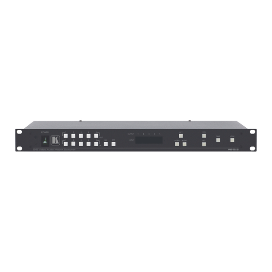
Your VS-5x5 5x5 Video Audio Matrix Switcher Figure 1: VS-5x5 5x5 Video Audio Matrix Switcher... -
Page 7: Table 1: Front Panel Vs-5X5 5X5 Video Audio Matrix Switcher Features
Your VS-5x5 5x5 Video Audio Matrix Switcher Table 1: Front Panel VS-5x5 5x5 Video Audio Matrix Switcher Features Feature Function IR Receiver The red LED is illuminated when receiving signals from the Infra-red remote control transmitter Power Switch Illuminated switch for turning the unit ON or OFF... -
Page 8: Figure 2: Vs-5X5 5X5 Video Audio Matrix Switcher Underside View
Your VS-5x5 5x5 Video Audio Matrix Switcher Table 2: Rear Panel VS-5x5 5x5 Video Audio Matrix Switcher Features Feature Function LOOP BNC Connector For looping the inputs EXT. SYNC BNC Connects to the external SYNC source Connector Composite BNC OUT... -
Page 9: Connecting The Vs-5X5
3 See section 5.4 for a description of how to connect a balanced/unbalanced stereo audio input/output 4 Not illustrated in Figure 3 5 When less than five outputs are required, connect only those outputs of the VS-5x5 that are required, and leave the other outputs unconnected... -
Page 10: Controlling Via Rs-232 (For Example, Using A Pc)
To connect a PC to the VS-5x5 unit, using the Null-modem adapter provided with the machine (recommended): Connect the RS-232 DB9 rear panel port on the Master VS-5x5 unit to the Null-modem adapter and connect the Null-modem adapter with a 9 wire... -
Page 11: Controlling Via Rs-485
“ G” (Ground) PIN on one of the units (for example, on the RC-3000) 2. Set the VS-5x5 unit as MACHINE # 1, according to Table 4 (that is, DIP 1, DIP 2, DIP 3, and DIP 4 OFF), and set the other dipswitches on the... -
Page 12: Connecting The Balanced/Unbalanced Stereo Audio Input/Output
Connecting the VS-5x5 5.4 Connecting the Balanced/Unbalanced Stereo Audio Input/Output Figure 6, Figure 7, and Figure 8 illustrate how to wire a balanced/unbalanced input and/or output connection: Figure 6: Connecting the Balanced Stereo Audio Input/Output Figure 7: Connecting the Unbalanced Stereo Audio Input... -
Page 13: Setting The Dipswitches
The MACHINE # determines the position of a VS-5x5 unit, specifying which VS-5x5 unit is being controlled when several VS-5x5 units connect to a PC or serial controller. Set the MACHINE # on a VS-5x5 unit via DIPS 1, 2, 3 and 4, according to Table 4. -
Page 14: Controlling Via Rs-232 And Rs-485
Controlling via RS-232 and RS-485 Controlling via RS-232 and RS-485 You can cascade up to 16 VS-5x5 units with control from a PC or serial controller. To cascade up to 16 individual VS-5x5 units, via RS-232 and RS-485, do the following: 1. -
Page 15: Figure 10: Cascading Individual Units In A Control Configuration Via Rs-232 And Rs-485
Controlling via RS-232 and RS-485 Figure 10: Cascading Individual Units in a Control Configuration via RS-232 and RS-485 KRAMER: SIMPLE CREATIVE TECHNOLOGY... -
Page 16: Operating The Vs-5X5
Infra-red remote control transmitter 7.1 Displaying Unit Characteristics The VS-5x5 unit characteristics are displayed in the following circumstances: Immediately (and automatically) after switching on the power; and When simultaneously pressing the 3 “ IN” buttons 1, 2 and 3, for 3... -
Page 17: Setting The Audio-Follow-Video Option
7.4 Confirming Settings Choose to work in the AT ONCE or the CONFIRM mode, as section 7.4.1 describes. When the VS-5x5 operates in the AT ONCE mode (TAKE button is not lit), pressing an OUT-IN combination implements the switch immediately. In the CONFIRM mode (TAKE button is lit), the TAKE button must be pressed to authorize the switch. -
Page 18: Toggling Between The At Once And Confirm Modes
Operating the VS-5x5 In the AT ONCE mode, you save time as execution is immediate and actions require no user confirmation. However, no protection is offered against changing an action in error. In the CONFIRM mode: You can key-in several actions and then confirm them by pressing the... -
Page 19: Storing/Recalling Input/Output Configurations
The memory recalls the stored data from that reference. Tip: If you cannot remember which of the 10 input/output configurations is the one that you want, set the VS-5x5 to the CONFIRM mode and manually scan all the input/output configurations until you locate it. -
Page 20: Deleting An Input/Output Configuration
1 Storing a new configuration over a previous configuration (without deleting it first) replaces the previous configuration 2 Nevertheless, even though the front panel is locked you can still operate via RS-232 or RS-485, as well as via the Kramer... -
Page 21: Flash Memory Upgrade
Before installing the latest Kramer firmware version on a VS-5x5 unit, do the following: 1. Connect the RS-232 DB9 rear panel port on the VS-5x5 unit to the Null-modem adapter and connect the Null-modem adapter with a 9 wire flat cable to the RS-232 DB9 COM port on your PC (see section 5.2). -
Page 22: Upgrading Firmware
Flash Memory Upgrade 8.3 Upgrading Firmware Follow these steps to upgrade the firmware: 1. Double click the desktop icon: “ Shortcut to FLIP.EXE” . The Splash screen appears as follows: Figure 13: Splash Screen 2. After a few seconds, the Splash screen is replaced by the “ Atmel – Flip” window: Figure 14: Atmel –... -
Page 23: Figure 15: Device Selection Window
Figure 15: Device Selection Window 4. Click the button next to the name of the device and select from the list: AT89C51RD2: AT89C51RD2 T89C51RD2 Figure 16: Device Selection window 5. Click OK and select “Load Hex” from the File menu. KRAMER: SIMPLE CREATIVE TECHNOLOGY... -
Page 24: Figure 17: Loading The Hex
Figure 17: Loading the Hex 6. The Open File window opens. Select the correct HEX file that contains the updated version of the firmware for VS-5x5 (for example 5x5M_V1p2.hex) and click Open. 7. Press the keyboard shortcut key F3 (or select the “ Communication / RS232”... -
Page 25: Figure 19: Atmel - Flip Window (Connected)
Memory Verify Pass appears VP1608.hex Figure 20: Atmel – Flip Window (Operation Completed) 1 See also the blue progress indicator on the status bar 2 If an error message: “ Not Finished” shows, click Run again KRAMER: SIMPLE CREATIVE TECHNOLOGY... -
Page 26: Technical Specifications
Technical Specifications 10. Close the “Atmel – Flip” window. 11. Disconnect the power on the VS-5x5. 12. Disconnect the RS-232 rear panel port on the VS-5x5 unit from the Null-modem adapter. 13. Release FLASH PROG button on rear panel (Table 2). -
Page 27: Table Of Hex Codes For Serial Communication
42 changes to the “ audio outputs gain adjustment” mode. Table 7 lists the Hex values for the audio gain control of the 5 inputs. 1 See Protocol 2000 description in section 12 KRAMER: SIMPLE CREATIVE TECHNOLOGY... -
Page 28: Table 7: Vs-5 5 Hex Codes For Audio Input Gain Control
Tables of Hex Codes for Audio Input/Output Gain Control Table 7: VS-5 5 Hex Codes for Audio Input Gain Control INPUTS 1 See Protocol 2000 description in section 12... -
Page 29: Tables Of Hex Codes For Audio Output Gain Control
42 changes to the “ audio inputs gain adjustment” mode. Table 8 lists the Hex values for the audio gain control of the 5 outputs. 1 See Protocol 2000 description in section 12 KRAMER: SIMPLE CREATIVE TECHNOLOGY... -
Page 30: Table 8: Vs-5 5 Hex Codes For Audio Output Gain Control
Tables of Hex Codes for Audio Input/Output Gain Control Table 8: VS-5 5 Hex Codes for Audio Output Gain Control OUTPUTS *In the Mute state, the audio output is physically disconnected from the input 1 See Protocol 2000 description in section 12... -
Page 31: Kramer Protocol 2000
Kramer Protocol 2000 12 Kramer Protocol 2000 The VS-5x5 is compatible with Kramer’s Protocol 2000 (version 0.42) (below). This RS-232 / RS-485 communication protocol uses four bytes of information as defined below. For RS-232, a null-modem connection between the machine and controller is used. The default data rate is 9600 baud, with no parity, 8 data bits and 1 stop bit. -
Page 32: Table 10: Instruction Codes For Protocol 2000
Kramer Protocol 2000 Table 10: Instruction Codes for Protocol 2000 Note: All values in the table are decimal, unless otherwise stated. INSTRUCTION DEFINITION FOR SPECIFIC INSTRUCTION NOTE DESCRIPTION INPUT OUTPUT 0, 18 RESET SWITCH VIDEO Set equal to video input which is... - Page 33 5 or 7, the machine will send its name. The reply is the decimal value of the INPUT and OUTPUT. For example, for a 2216, the reply to the request to send the audio machine name would be (HEX codes): 81 (i.e. 128dec+ 22dec for 2nd byte, and 128dec+ 16dec for 3rd byte). KRAMER: SIMPLE CREATIVE TECHNOLOGY...
- Page 34 Kramer Protocol 2000 If the request for identification is sent with the INPUT set as 3 or 4, the appropriate machine will send its software version number. Again, the reply would be the decimal value of the INPUT and OUTPUT - the INPUT representing the number in front of the decimal point, and the OUTPUT representing the number after it.
- Page 35 NOTE 23 – Further information needed in instructions 21, 22, 25 and 26, is sent using instruction 42 – which is sent prior to the instruction. For example, to request the audio gain value of right input # 9, send hex codes and then send HEX codes KRAMER: SIMPLE CREATIVE TECHNOLOGY...
- Page 36 EXCLUSION OF DAMAGES The liability of Kramer for any effective products is limited to the repair or replacement of the product at our option. Kramer shall not be liable for: Damage to other property caused by defects in this product, damages based upon inconvenience, loss of use of the product, loss of time, commercial loss;...
- Page 37 For the latest information on our products and a list of Kramer distributors, visit our Web site: www.kramerelectronics.com, where updates to this user manual may be found. We welcome your questions, comments and feedback. Kramer Electronics, Ltd. Web site: www.kramerelectronics.com E-mail: info@kramerel.com...
Need help?
Do you have a question about the VS-5x5 and is the answer not in the manual?
Questions and answers