Table of Contents
Advertisement
Quick Links
Advertisement
Table of Contents

Related Manuals for Xilinx AMS101


Summary of Contents for Xilinx AMS101
- Page 1 AMS101 Evaluation Card User Guide UG886 (v1.3) November 6, 2013...
-
Page 2: Revision History
(including loss of data, profits, goodwill, or any type of loss or damage suffered as a result of any action brought by a third party) even if such damage or loss was reasonably foreseeable or Xilinx had been advised of the possibility of the same. - Page 3 Revision 02/14/2013 Chapter 1, AMS101 Evaluation Card Overview: Instances of AMS101 evaluator tool were corrected to AMS evaluator tool. Added part HW-AMS101-G. Reference design files are now downloaded from www.xilinx.com/support/documentation/ams101_evaluation_card.htm. The AC701 board is now supported. The bullet with “...
- Page 4 AMS101 Evaluation Card User Guide www.xilinx.com UG886 (v1.3) November 6, 2013...
-
Page 5: Table Of Contents
..............7 Chapter 2: AMS101 Evaluation Card Quick Start Quick Start . - Page 6 ..............56 www.xilinx.com AMS101 Evaluation Card User Guide UG886 (v1.3) November 6, 2013...
-
Page 7: Chapter 1: Ams101 Evaluation Card Overview
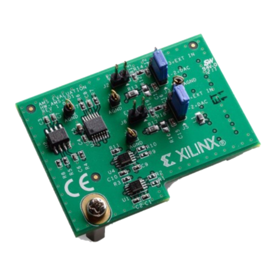
Overview AMS101 Evaluation Card The Xilinx 7 series FPGAs and Zynq-7000® All Programmable System on a Chip (AP SoC) each feature two 1 Mega-sample per second (MSPS), 12-bit, Xilinx analog-to-digital converters (XADCs) built into the device (FPGA or SoC). The Analog Mixed Signal (AMS) technology combines the XADC analog measurement with the device’s logic for simple... - Page 8 Chapter 1: AMS101 Evaluation Card Overview X-Ref Target - Figure 1-1 AMS101 Evaluation Card XADC Header (Under AMS101 Card) UG886_c1_01_091012 Figure 1-1: KC705 Evaluation Board with the AMS101 Evaluation Card Installed X-Ref Target - Figure 1-2 UG886_c1_02_020113 Figure 1-2: AMS101 Evaluation Card Features www.xilinx.com AMS101 Evaluation Card User Guide UG886 (v1.3) November 6, 2013...
- Page 9 Overview Table 1-1: AMS101 Evaluation Card Features Callout Component Description Jumpers to select DAC or external signal source. 20-pin connector to the XADC header on the FPGA or AP SoC base board. Pins allow for external analog input signals. Digital I/O level translators.
- Page 10 Chapter 1: AMS101 Evaluation Card Overview www.xilinx.com AMS101 Evaluation Card User Guide UG886 (v1.3) November 6, 2013...
-
Page 11: Chapter 2: Ams101 Evaluation Card Quick Start
Configurable analog inputs • An interactive GUI • Interfaces for all the latest Xilinx FPGA or AP SoC base boards, including the KC705 Kintex-7 FPGA base board, as detailed in this document. (See the full list of supported base boards in Appendix AMS101 Evaluation Card User Guide www.xilinx.com... -
Page 12: Quick Start
The GUI itself has been built using National Instruments LabVIEW 2011 software. To enable use of the GUI without the need for a LabVIEW license, Xilinx has bundled the LabVIEW run-time engine with the GUI installer. During the installation process, the run time engine is installed on the PC. - Page 13 PC, and the JTAG Standard-A plug to Micro-B plug USB programming cable. Figure 2-3 shows how to connect these on the KC705 base board. Caution! Do not turn on the power switch until step 6, page AMS101 Evaluation Card User Guide www.xilinx.com UG886 (v1.3) November 6, 2013...
- Page 14 Connect the AMS101 evaluation card to the XADC header on the base board. The AMS101 evaluation card connects to the FPGA base board by plugging the card into the XADC header on the base board. The AMS101 evaluation card connector and XADC header socket are keyed to align properly.
- Page 15 Quick Start Ensure that all the jumper settings are correct on the AMS101 evaluation card. Figure 2-5 shows an example of jumpers J3 and J5 (DACs enabled). Table 2-1 explains additional jumpers. Note: Figure 2-5 The image in is for reference only and might not reflect the current revision of the board.
- Page 16 [Ref 1], for more specific instructions on downloading the design. For the AMS101 evaluation card to function, the FPGA needs to be programmed with the appropriate design. To do this, download the design to the FPGA: Open the Vivado ® Design Suite. Here is one example path for Vivado tools: Start menu/Xilinx Design Tools/Vivado 2013.3/Vivado 2013.3...
- Page 17 If the AMS Evaluator tool GUI was successfully installed, an icon should be displayed on the desktop and in the Windows start menu (see Figure 2-8). To open the AMS Evaluator tool GUI, click the red Xilinx X icon. The GUI shown in Figure 2-9 should appear.
- Page 18 Chapter 2: AMS101 Evaluation Card Quick Start X-Ref Target - Figure 2-9 Select COM Port Here UG886_c2_09_092512 Figure 2-9: AMS Evaluator Tool on Start-Up Connect to the UART port as detailed in the appropriate FPGA/processor base board Getting Started Guide: •...
- Page 19 Quick Start X-Ref Target - Figure 2-10 UG886_c2_10_092512 Figure 2-10: UART-USB Port in Device Manager AMS101 Evaluation Card User Guide www.xilinx.com UG886 (v1.3) November 6, 2013...
- Page 20 Chapter 2: AMS101 Evaluation Card Quick Start Select the appropriate COM port from the pull-down menu on the GUI as show in Figure 2-11. Then click the Connect button. After the AMS Evaluator tool is connected, the kit name is displayed below the green Connected circle. If the AMS Evaluator tool is unable to connect, be sure the correct COM port is selected and click refresh.
-
Page 21: Run Key Performance Tests
Run Key Performance Tests Run Key Performance Tests All of the software and hardware should be configured and running. The AMS101 evaluation card can now be used to perform measurement tests on the XADC. Collect Time Domain Data To collect time domain data, press the Collect Data button shown in Figure 2-12. - Page 22 Chapter 2: AMS101 Evaluation Card Quick Start Perform Fast Fourier Transform Analysis To analyze the performance of the XADC in the frequency domain, select the Frequency Domain tab (see Figure 2-13). When selected, a Fast Fourier Transform (FFT) is performed on the XADC data just viewed in the time domain.
- Page 23 Figure 2-14. X-Ref Target - Figure 2-14 Perform Linearity Test and Initiate Analog Ramp Output at DAC UG886_c2_14_092512 Figure 2-14: Linearity Error Data Capture and Analysis AMS101 Evaluation Card User Guide www.xilinx.com UG886 (v1.3) November 6, 2013...
-
Page 24: Analyze Internal Voltage And Temperature Sensors
Chapter 2: AMS101 Evaluation Card Quick Start Analyze Internal Voltage and Temperature Sensors The XADC also has several internal sensors that it digitizes. These include a temperature sensor and FPGA voltage supply sensors. Select the Sensor Data tab to view the data... - Page 25 3.3V supply, MGTAVCC, and MGTAVTT are available on the AC701 board's onboard MUX positioned at U14. The differential output of the MUX is connected to auxiliary pin 9 (V P/N 9) of XADC. AMS101 Evaluation Card User Guide www.xilinx.com UG886 (v1.3) November 6, 2013...
- Page 26 Chapter 2: AMS101 Evaluation Card Quick Start The voltage, current, and power calculation of each rail is displayed in the Power Monitor tab on the AMS Evaluator GUI as shown in Figure 2-16. The Power Monitor tab is designed specifically for the AC701 board and is not available on the other AMS Targeted Reference Designs (ZC702, KC705, or VC707).
- Page 27 , the 1.8V supply, the 3.3V supply, MGTAVCC, and MGTAVTT). CCO_ADJ X-Ref Target - Figure 2-17 UG886_c2_17_011513 Figure 2-17: AC701 Power Monitor Design Measuring V , the 1.8V Supply, CCO_ADJ the 3.3V Supply, and MGTAVCC AMS101 Evaluation Card User Guide www.xilinx.com UG886 (v1.3) November 6, 2013...
- Page 28 Chapter 2: AMS101 Evaluation Card Quick Start X-Ref Target - Figure 2-18 UG886_c2_18_020113 Figure 2-18: AC701 Power Monitor Design Measuring MGTAVCC and MGTAVTT www.xilinx.com AMS101 Evaluation Card User Guide UG886 (v1.3) November 6, 2013...
-
Page 29: Chapter 3: Ams101 Evaluation Hardware
I/O Level Translator Ref erence 16-Bit 16-Bit Voltage AD8033 5V Power Ground VP/VAUX0P/VAUX8P VN/VAUX0N/VAUX8N 3-way jumpers Positive External Negative Source External Source UG886_c3_01_062712 Figure 3-1: AMS101 Evaluation Card Block Diagram AMS101 Evaluation Card User Guide www.xilinx.com UG886 (v1.3) November 6, 2013... -
Page 30: Interfacing To The Fpga Base Board
3-way jumper pins to select DAC source or external source going to XADC header Interfacing to the FPGA Base Board The AMS101 evaluation card has a 20-pin header that allows it to be plugged into the XADC header, which is now available on all Xilinx 7 series FPGA and Zynq-7000 SoC base boards. -
Page 31: Board Setup
Board Setup Onboard Signal Source The AMS101 card contains the Analog Devices AD5065 part, which is a dual 16-bit DAC. This DAC can be used for one of three functions: • Provide a ramp for linearity testing • Generate a sine wave for a quick dynamic performance test •... - Page 32 Chapter 3: AMS101 Evaluation Hardware X-Ref Target - Figure 3-3 VP/VAUX0P/VAUX8P VN/VAUX0N/VAUX8N UG886_c3_03_092512 Figure 3-3: Use Case 1 Block Diagram To enable this use case, connect jumpers J3 and J5 between pins 1 and 2 as shown in Figure 3-4. Only these two jumpers need to be populated. DAC A always supplies the...
- Page 33 Board Setup Use Case 1 enables all tests and all modes. To operate the AMS101 evaluation card in any one of those modes, see XADC Configuration, page 38. If the optimum dynamic performance is required, use an external signal source. Select an appropriate Use Case (2 or...
- Page 34 Chapter 3: AMS101 Evaluation Hardware X-Ref Target - Figure 3-6 Triangle Near Jumpers Indicates Pin 1 Black Filled Boxes Indicate Jumper Position Jumper J2 Jumper J3 Ground Apply Positive Analog Input Signal to Pin 1 Jumper J5 Apply Negative Analog Input Voltage with “Vn...
- Page 35 Input Signal to Pin 1 Jumper J6 Jumper J5 Ground Apply Negative Analog Input Signal to Pin 1 UG886_c3_08_081612 Figure 3-8: Use Case 3 Jumper Configurations: Differential External Analog Source AMS101 Evaluation Card User Guide www.xilinx.com UG886 (v1.3) November 6, 2013...
- Page 36 Chapter 3: AMS101 Evaluation Hardware www.xilinx.com AMS101 Evaluation Card User Guide UG886 (v1.3) November 6, 2013...
-
Page 37: Chapter 4: Ams Evaluator Tool
• Export measurement results to a CSV file. • Leverage the FPGA to improve the performance of the XADC using Xilinx Analog Mixed Signal (AMS) technology. The AMS Evaluator tool allows selection of various measurements by choosing various tabs across the top of the GUI as shown in Figure 4-1. -
Page 38: Xadc Configuration
Channel Options pull-down menu located in the XADC control panel (see Figure 4-2). After the Channel Options pull-down menu changes, the appropriate data is written to the XADC registers. www.xilinx.com AMS101 Evaluation Card User Guide UG886 (v1.3) November 6, 2013... - Page 39 961.54 kSPS. See 7 Series FPGAs and Zynq-7000 All Programmable SoC XADC Dual 12-Bit 1 MSPS Analog-to-Digital Converter User Guide (UG480) [Ref 6] for more details on the clocking of the XADC. AMS101 Evaluation Card User Guide www.xilinx.com UG886 (v1.3) November 6, 2013...
- Page 40 Figure 4-4: XADC Sample Rate Changes Signal Source Configuration The AMS101 evaluation card uses an AD5065 dual 16-bit DAC as a signal source to the XADC. When either the Time Domain or Frequency Domain tabs are selected, the GUI provides access to the control of the DAC through the DAC control panel on the GUI, as...
-
Page 41: Xadc Performance Tests
0.25V 0.5V XADC Performance Tests A selection of tabs is located across the top of the AMS Evaluator tool under the Xilinx logo. Time Domain, Frequency Domain, Linearity, and Sensor Data tabs are associated with XADC performance tests. Time Domain The Time Domain tab gives access to XADC data without any post processing. - Page 42 Blackman-Harris window, and five bins on either side of the fundamental are discarded in the SNR calculation. X-Ref Target - Figure 4-6 Windowing Method Number of Bins Ignored in Employed SNR Calculation UG886_c4_06_092512 Figure 4-6: Windowing Options www.xilinx.com AMS101 Evaluation Card User Guide UG886 (v1.3) November 6, 2013...
- Page 43 X-Ref Target - Figure 4-7 Change the actual voltages being applied to the FPGA with the Texas Instruments UCD9248 power controller. UG886_c4_07_110413 Figure 4-7: Sensor Data Tab and Power Control Panel AMS101 Evaluation Card User Guide www.xilinx.com UG886 (v1.3) November 6, 2013...
-
Page 44: Ams Demonstration
The Analog Mixed Signal (AMS) technology leverages the digital signal processing capabilities of Xilinx FPGA interconnect logic to enhance the performance and functionality of the local XADC block. The AMS101 evaluation card offers a very limited glimpse into the possibilities of the AMS concept by enabling efficient decimation. - Page 45 Decimation is a powerful way of improving the SNR, SINAD, and ENOB. Figure 4-2 details a sample of typical results with the AMS101 evaluation card connected to various base boards. Table 4-2: AMS101 Evaluation Card Typical Results with Multiple Base Boards...
- Page 46 Chapter 4: AMS Evaluator Tool www.xilinx.com AMS101 Evaluation Card User Guide UG886 (v1.3) November 6, 2013...
-
Page 47: Appendix A: Targeted Design Platforms, Schematics, And Dynamic
Supported demonstration design platforms include the ZC706 and ZedBoard. See the AMS101 Evaluation Card website for the ZC706 and ZedBoard AMS demo designs. Schematics Schematics for the AMS101 evaluation card are shown in Figure A-1 Figure A-2. AMS101 Evaluation Card User Guide www.xilinx.com... - Page 48 XADC_VCC5V0 DACOUTA_R DACOUTA 0.1UF 0.1UF SN74LVC2T45DCT 3300PF 1/8W VCCA VCCB XADC_GPIO_1 SCLK XADC_AGND XADC_GPIO_0 LDAC_B VADJ 1/10W 1/10W dct8-14x70 UG886_aA_01_062512 Figure A-1: AMS101 Evaluation Card Schematic (1 of 2) www.xilinx.com AMS101 Evaluation Card User Guide UG886 (v1.3) November 6, 2013...
-
Page 49: Dynamic Performance Metric Calculation Methodology
XADC_AGND XADC_AGND UG886_aA_02_062512 Figure A-2: AMS101 Evaluation Card Schematic (2 of 2) Dynamic Performance Metric Calculation Methodology SNR is calculated by removing the DC, the fundamental, and the first five harmonics components from the FFT data. All the remaining components are root sum squared together. - Page 50 Appendix A: Targeted Design Platforms, Schematics, and Dynamic Performance Metric Calculation www.xilinx.com AMS101 Evaluation Card User Guide UG886 (v1.3) November 6, 2013...
-
Page 51: Jumper Settings For The Kc705 Board
Required Jumper Settings for Base Boards Jumper Settings for the KC705 Board Note: The triangle indicates pin 1 for jumper settings on all Xilinx base boards. To enable AMS evaluation, ensure the KC705 board has the following jumper settings: • J43: In place •... -
Page 52: Jumper Settings For The Zc706 Board
J54: In place between pins 2 and 3 • J42: In place between pins 1 and 2 See AC701 Evaluation Board for the Artix-7 FPGA User Guide (UG952) [Ref 11]. www.xilinx.com AMS101 Evaluation Card User Guide UG886 (v1.3) November 6, 2013... -
Page 53: Appendix C: Additional Resources
Topics include design assistance, advisories, and troubleshooting tips References The most up to date information related to the AMS101 Evaluation Card and its documentation is available on these websites: AMS101 Evaluation Card... - Page 54 10. Zynq-7000 All Programmable SoC ZC706 Evaluation Kit Getting Started Guide (ISE Design Suite and Vivado Design Suite) (UG961) 11. AC701 Evaluation Board for the Artix-7 FPGA User Guide (UG952) www.xilinx.com AMS101 Evaluation Card User Guide UG886 (v1.3) November 6, 2013...
- Page 55 This product is designed and tested to conform to the European Union directives and standards described in this section. Declaration of Conformity See the AMS101 Evaluation Card CE Declaration of Conformity. Directives 2006/95/EC, Low Voltage Directive (LVD) 2004/108/EC, Electromagnetic Compatibility (EMC) Directive...
- Page 56 This product complies with Directive 2002/95/EC on the restriction of hazardous substances (RoHS) in electrical and electronic equipment. This product complies with CE Directives 2006/95/EC, Low Voltage Directive (LVD) and 2004/108/EC, Electromagnetic Compatibility (EMC) Directive. www.xilinx.com AMS101 Evaluation Card User Guide UG886 (v1.3) November 6, 2013...
Need help?
Do you have a question about the AMS101 and is the answer not in the manual?
Questions and answers